Report of Geotechnical Exploration For Baymeadows Road/Old Still PUD 6 inch Reclaimed Water Main Jacksonville, FL
|
|
|
- Meryl Carter
- 5 years ago
- Views:
Transcription


1 Report of Geotechnical Exploration For Baymeadows Road/Old Still PUD inch Reclaimed Water Main Jacksonville, FL MAE Project No June, 0 Prepared for: CPH, Inc. 00 Belfort Road, Suite 0 Jacksonville, FL Prepared by: 9 Western Way, Suite Jacksonville, Florida Phone (90) Fax (90) 9 99
2 June, 0 Mr. Wade P. Olszewski, P.E. CPH, Inc. 00 Belfort Road, Suite 0 Jacksonville, FL Reference: Report of Geotechnical Exploration Baymeadows Road/Old Still PUD inch Reclaimed Water Main Jacksonville, Florida MAE Project No Dear Mr. Olszewski: Meskel & Associates Engineering, LLC has completed a geotechnical exploration for the subject project. Our work was authorized through your Purchase Order 0, dated December 0, 0 (CPH Project Number J) and was performed in general accordance with our revised proposal dated November, 0. The geotechnical exploration was performed to evaluate the encountered subsurface conditions along the proposed pipeline route and to provide recommendations to support design of the proposed pipeline construction. A summary of our findings is presented below for your convenience; however, we recommend that this report be considered in its entirety. The soil borings encountered a surficial topsoil layer measuring approximately inches in thickness, underlain by fine sands and fine sands with silt (A ) to the boring termination depths of 0 feet below existing grade. Due to overhead powerlines, planned SPT borings (B through B ) were offset about feet to the north of the original planned boring locations. However, hand augers (A through A ) were performed at each of the original boring locations, and soil profiles similar to the general soil profiles were encountered to their termination depths of feet below the existing grade. As an exception to the relatively uniform soil profiles, soils containing unsuitable organic material (A ) were encountered at boring locations B and B from between approximately to ½ feet and to feet (respectively) below the existing ground surface. In addition, wood debris was encountered at the boring B location between approximately to feet below the existing grade. Groundwater was encountered at depths ranging from feet inches to 9 feet inches below the existing ground surface. It is our opinion that the proposed pipeline construction may be supported on the existing subsurface soil conditions provided site preparation is performed in accordance with the recommendations presented in this report. We appreciate this opportunity to be of service as your geotechnical consultant on this phase of the project. If you have any questions, or if we may be of any further service, please contact us. Sincerely, MAE MESKEL FL Certificate & ASSOCIATES of Authorization ENGINEERING, No. LLC W. Josh Mele, E.I. Brett Harbison, P.E. Staff Engineer Director, Geotechnical Services Registered, Florida No. 9 Distribution: Mr. Wade P. Olszewski, P.E. pdf 9 Western Way, Suite, Jacksonville, Florida p
3 Baymeadows Road/Old Still PUD inch Reclaimed Water Main MAE Report No TABLE OF CONTENTS Subject Page No..0 PROJECT INFORMATION.... General.... Project Description....0 FIELD EXPLORATION.... SPT and Auger Borings.... Pavement Cores.... Bulk Soil Sampling....0 LABORATORY TESTING.... Visual Classification.... Soil Index Tests.... Corrosion Series Tests....0 GENERAL SUBSURFACE CONDITIONS.... General Soil Profile.... Groundwater Level.... Review of the USDA Web Soil Survey Map.... Seasonal High Groundwater Level.... Pavement Core Samples....0 DESIGN RECOMMENDATIONS.... General.... Pipeline Support Recommendations.... Environmental Classification....0 SITE PREPARATION AND EARTHWORK RECOMMENDATIONS.... Clearing.... Temporary Groundwater Control.... Preparation of Pipe Bedding Soils.... Compaction of Pipe Bedding Soil Excavation Protection Pipe Backfill Placement and Compaction QUALITY CONTROL TESTING....0 REPORT LIMITATIONS... 9 Western Way, Suite Jacksonville, Florida Phone: (90)9 990 Fax: (90)9 99 Page i
4 Baymeadows Road/Old Still PUD inch Reclaimed Water Main MAE Report No FIGURES Figure. Figure. Figures. Site Location Map Boring Location Plan Generalized Soil Profiles APPENDICES Appendix A. Appendix B. Appendix C. Appendix D. Soil Boring Logs Field Exploration Procedures Key to Boring Logs Key to Soil Classification Summary of Laboratory Test Data Laboratory Test Procedures Summary of Corrosion Series Test Results Pavement Core Pictures 9 Western Way, Suite Jacksonville, Florida Phone: (90)9 990 Fax: (90)9 99 Page ii
5 Baymeadows Road/Old Still PUD inch Reclaimed Water Main MAE Report No PROJECT INFORMATION. General Project information was provided to us by Mr. Wade P. Olszewski, P.E. with CPH, Inc. through several s and telephone conversations.. Project Description The site for the subject project is located along Baymeadows Road, between Point Meadows Drive and R.G. Skinner Parkway in Jacksonville, Florida. A portion of the pipeline within the Right of Way of Interstate 9 was not part of our scope of services for the project. It is our understanding that section was performed under a separate contract by others. The general site location is shown on the Site Location Map, Figure. Based on the provided information and our discussions with Mr. Olszewski, it is our understanding that the project includes the construction of approximately,00 linear feet of inch diameter reclaimed water main to be installed along the northern side Right of Way of Baymeadows Road. It is understood that our services for this project were to include geotechnical field exploration and engineering services to support design of the proposed pipeline construction, and the field, laboratory and professional services required towards obtaining a FDEP Generic Permit for the Discharge of Groundwater. This report covers the exploration to support design of the proposed pipeline construction. The environmental investigation will be reported under separate cover..0 FIELD EXPLORATION A field exploration was performed on January, February and, 0. The approximate boring locations are included on the Boring Location Plan, Figure. The boring location GPS coordinates were determined by us using Google Earth, and then located in the field by our personnel using a Garmin GPSMAP hand held GPS receiver; therefore, the boring locations shown on Figure should be considered accurate only to the degree implied by the method of measurement used.. SPT and Auger Borings To explore the subsurface conditions within the area of the proposed reclaimed water main alignment, we located and performed Standard Penetration Test (SPT) borings, drilled to depths of approximately 0 feet below the existing ground surface, in general accordance with the methodology outlined in ASTM D. Split spoon soil samples recovered during performance of the borings were visually described in the field and representative portions of the samples were transported to our laboratory for further evaluation. Overhead utilities prevented access by our drill rig to five of the SPT locations along the proposed reclaimed water main. Therefore, auger borings using a hand held bucket auger were located at the original position of each of the five offset SPT borings to explore the shallow subsurface conditions along that section of the pipeline alignment. Each auger boring was advanced to a depth of approximately feet below the existing ground surface in general accordance with the methodology outlined in ASTM D. Representative soil samples were also recovered from the auger borings and returned to our laboratory for further evaluation. A summary of the field procedures for both the SPT and auger borings 9 Western Way, Suite Jacksonville, Florida Phone: (90)9 990 Fax: (90)9 99 Page
6 Baymeadows Road/Old Still PUD inch Reclaimed Water Main MAE Report No are included in Appendix A.. Pavement Cores Four core samples of the existing pavement structure (asphalt surface, base course) were obtained. Each core location was drilled using a inch diameter diamond coated core barrel connected to free standing mechanical drill equipment. Water was used during core sampling to cool the core barrel and to limit dust and debris generated from the coring process. The pavement layers (asphalt and base courses) were measured in the field by the field crew, and the recovered asphalt surface core samples were transported to our laboratory. Once the cores were complete, the holes were backfilled with an asphalt cold patch material in compacted lifts. Asphalt layer thicknesses ranged from ¼ inches to ¾ inches. Photographs of the recovered asphalt core samples are included in Appendix D.. Bulk Soil Sampling Three, gallon bulk soil samples were obtained within the planned reclaimed water main alignment for corrosion series testing. These bulk soil samples were collected from borings located along the proposed reclaimed water main alignment (A, B, B 9) at depths between and feet below existing grade and then transported to our laboratory for classification and testing. A Summary of Corrosion Series Test Results is included in Appendix C..0 LABORATORY TESTING. Visual Classification Representative soil samples obtained during our field exploration were visually classified by a geotechnical engineer using the AASHTO Soil Classification System in general accordance with ASTM D. A Key to the Soil Classification System is included in Appendix A.. Soil Index Tests Quantitative laboratory testing was performed on selected samples of the soils encountered during the field exploration to better define the composition of the soils encountered and to provide data for correlation to their anticipated strength and compressibility characteristics. The laboratory testing determined the percent fines, natural moisture and organic content of selected soil samples. The results of the laboratory testing are shown in the Summary of Laboratory Test Data included in Appendix B. Also, these results are shown on the Generalized Soil Profiles (Figures through ) and on the Log of Boring records at the respective depths from which the tested samples were recovered.. Corrosion Series Tests Three bulk soil samples were selected for corrosion potential testing. These samples were obtained from borings located along the proposed reclaimed water main alignment (A, B, B 9) at depths from to feet below the existing ground surface. The testing included soil ph, resistivity, and chloride and sulfate contents. The test results are discussed in Section. below, and are presented on the Summary of Corrosion Series Test Results in Appendix C. 9 Western Way, Suite Jacksonville, Florida Phone: (90)9 990 Fax: (90)9 99 Page
7 Baymeadows Road/Old Still PUD inch Reclaimed Water Main MAE Report No GENERAL SUBSURFACE CONDITIONS. General Soil Profile Graphical presentation of the generalized subsurface conditions is presented on the Generalized Soil Profiles, Figures through. Detailed boring records are included in Appendix A. When reviewing the Profiles and boring records, it should be understood that the soil conditions will vary between the boring locations. In general, the borings encountered a surficial topsoil layer measuring approximately inches, underlain by fine sands and fine sands with silt (A ) to the boring termination depths of feet (hand augers) and 0 feet (SPT borings) below the existing grade. Trace to few amounts of organic fines and small to large roots were encountered within the sandy soils at several boring locations. In addition, several borings encountered near surface sandy soils with trace to few amounts of gravel (limestone fragments). The relative densities of the soils encountered ranged from very loose to very dense, typically increasing with depth. As exceptions: Boring B encountered a layer of highly organic silty fine sand (A ) from between approximately to ½ feet below the existing grade. Boring B encountered a layer of wood debris between approximately to feet below the existing grade. Boring B encountered a layer of organic fine sand (A ) from between approximately to feet below existing ground surface.. Groundwater Level The groundwater level was encountered at each of the boring locations and recorded at the time of drilling at depths varying from feet inches to 9 feet inches below the existing ground surface. However, it should be anticipated that the groundwater levels will fluctuate seasonally and with changes in climate. As such, we recommend that the water table be measured prior to construction. Measured groundwater levels are shown the boring profiles and boring logs.. Review of the USDA Web Soil Survey Map The results of a review of the USDA Soil Survey Conservation Service (SCS) Web Soil Survey of Duval County are shown in the table below. The soil drainage class, hydrological group, and estimated seasonal high groundwater levels reported in the Soil Survey are as follows: Map Unit Symbol Map Unit Name Drainage Class Hydrologic Group Depth to the Water Table () (inches) Evergreen Wesconnett complex (), depressional, 0 to percent slopes Very Poorly Drained A/D 0 9 Western Way, Suite Jacksonville, Florida Phone: (90)9 990 Fax: (90)9 99 Page
8 Baymeadows Road/Old Still PUD inch Reclaimed Water Main MAE Report No Map Unit Symbol Map Unit Name Drainage Class Hydrologic Group Depth to the Water Table () (inches) Hurricane and Ridgewood soils, 0 to percent slopes Somewhat Poorly Drained A to Leon fine sand, 0 to percent slopes Lynn Haven fine sand, 0 to percent slopes Poorly Drained A/D to Poorly Drained A/D 0 to Mandarin fine sand, 0 to percent slopes Somewhat Poorly Drained A to 0 Ortega fine sand, 0 to percent slopes Moderately Well Drained A to 9 Pamlico muck, depressional, 0 to percent slopes Very Poorly Drained A/D 0 () The Water Table above refers to a saturated zone in the soil which occurs during specified months, typically the summer wet season. Estimates of the upper limit shown in the Web Soil Survey are based mainly on observations of the water table at selected sites and on evidence of a saturated zone, namely grayish colors (redoximorphic features) in the soil. A saturated zone that lasts for less than a month is not considered a water table. () The term complex, as defined by the USDA, refers to a map unit consisting of two or more soils or miscellaneous areas in such an intricate pattern or in such small areas that they cannot be shown separately on the map.. Seasonal High Groundwater Level In estimating seasonal high groundwater level, a number of factors are taken into consideration including antecedent rainfall, soil redoximorphic features (i.e., soil mottling), stratigraphy (including presence of hydraulically restrictive layers), vegetative indicators, effects of development, and relief points such as drainage ditches, low lying areas, etc. Based on our interpretation of the current site conditions, including the boring logs and review of published data, we estimate the seasonal high groundwater levels at the site to be generally to feet above the water levels measured at the time of our field work. It is possible that higher groundwater levels may exceed the estimated seasonal high groundwater level as a result of significant or prolonged rains. Therefore, we recommend that design drawings and specifications account for the possibility of groundwater level variations, and construction planning should be based on the assumption that such variations will occur. 9 Western Way, Suite Jacksonville, Florida Phone: (90)9 990 Fax: (90)9 99 Page
9 Baymeadows Road/Old Still PUD inch Reclaimed Water Main MAE Report No Pavement Core Samples The pavement layers (asphalt and base) as encountered at the core locations were measured in the field. The recovered asphalt core samples were returned to our laboratory to verify the thickness of the asphalt layers as measured in the field, and to observe the overall condition of the asphalt samples. The measured asphalt and base thicknesses at each of the described core locations are shown in the table below: Core No. GPS Coordinates: Longitude and Latitude Asphalt Thickness (in.) Limerock Base Thickness (in.) C. W 0. N ¼ C. W 0.0 N ¼ C 0.99 W 0. N ¾ ½ C 0. W 0.99 N ¼ Based on our observations, each core appears to consist of one distinct layers of asphalt, containing fine to coarse grained aggregate. No cracks were observed at the top, bottom and sides of the cores. A base material was encountered below the asphalt surface course that appeared to be limerock material. The limerock material appeared to be relatively dry at the time of our exploration. The subgrade soils below the limerock base at all four locations were fine sand (A )..0 DESIGN RECOMMENDATIONS. General The following evaluation and recommendations are based on the provided project information as presented in this report, results of the field exploration and laboratory testing performed, and the construction techniques recommended in Section.0 below. If the described project conditions are incorrect or changed after this report, or subsurface conditions encountered during construction are different from those reported, MAE should be notified so these recommendations can be re evaluated and revised, if necessary. We recommend that MAE review the plans and earthwork specifications to verify that the recommendations contained in this report have been properly interpreted and implemented.. Pipeline Support Recommendations It is our understanding that the inch diameter pipeline will have an invert elevation that is about feet or less below the existing ground surface to allow for the minimum cover requirement of 0 to inches. Based on the results of the subsurface exploration and laboratory testing as discussed in this report, we consider the subsurface conditions at the site adaptable for supporting the proposed pipeline when constructed upon properly prepared subgrade soils. As discussed earlier in the report, fine sands to fine sands with silt (A ), were encountered in each of the borings advanced as part of this exploration to the boring termination depths. These soils are considered suitable for support of the pipe as well as for pipe backfill. These soils should be placed and compacted as discussed in Section.0 below. 9 Western Way, Suite Jacksonville, Florida Phone: (90)9 990 Fax: (90)9 99 Page
10 Baymeadows Road/Old Still PUD inch Reclaimed Water Main MAE Report No Boring B encountered highly organic soils (A ) between depths of to ½ feet below the existing ground surface, boring B encountered wood fragments between depths of to feet, and boring B encountered organic fine sand (A ) between depths of to feet below the existing grade. These soils are not considered suitable for support of the pipeline, nor as pipe backfill. If these soils are encountered at or near the planned pipe invert elevation at this location (specifically at B and B ), we recommend the organic soils that are within inches of the pipe invert be removed and replaced with suitable structural fill soil as described in Section.0 below. In addition, wood debris was encountered at the boring B location between and feet below the existing grade. Any debris, if encountered at or near the planned pipe invert elevation, will have to be removed and replaced with suitable structural fill as described in Section.0. Our personnel should observe this removal process to confirm whether all organic soils and/or debris are removed prior to backfilling. Organic soils and/or soils containing debris should not be used as pipe backfill. These soils should be separated from the other soils during excavation and stockpiled for removal from the site. Assuming the project information as described in previous sections of this report is correct, and provided the site preparation and earthwork construction recommendations outlined in Section.0 of this report are performed, the following parameters may be used for design... Lateral Pressure Design Parameters Underground walls for the manhole structures that are backfilled on one side and restrained against rotation at the top, should be designed to resist lateral pressures from soil and groundwater based on the following equivalent fluid unit weights: Above Water Table Equivalent Fluid Density 0 lb/ft Below Water Table Equivalent Fluid Density 90 lb/ft For the design of lateral loads on below grade walls, we recommend that the groundwater level be assumed to be at the ground surface. Lateral pressure distributions in accordance with the above do not take into account forces from construction equipment, wheel loads or other surcharge loads. To account for this loading, a pressure equal to 0. times the anticipated surface surcharge should be applied over the full height of all walls... Resisting Lateral Forces Horizontal forces that act on pipeline structures such as thrust and anchor blocks can be resisted to some extent by the earth pressures that develop in contact with the buried perpendicular face of the block structure, and by shearing resistance mobilized along the block structures base and subgrade interface. Allowable passive earth pressure resistance may be determined using the following equivalent fluid densities: Above Water Table Equivalent Fluid Density 0 lb/ft Below Water Table Equivalent Fluid Density 0 lb/ft A safety factor of was used for the above values. It is assumed the block structures are surrounded by well compacted structural backfill, as described in Section. below, extending at least feet horizontally beyond the vertical bearing face. In addition, it is presumed that the block structures can withstand horizontal movements on the order of 0. inch before mobilizing full passive resistance. 9 Western Way, Suite Jacksonville, Florida Phone: (90)9 990 Fax: (90)9 99 Page
11 Baymeadows Road/Old Still PUD inch Reclaimed Water Main MAE Report No The allowable sliding shearing resistance mobilized along the base of the block structure may be determined by the following formula: P = / V tan ( / ϕ) Where: P = Allowable shearing resistance force V = Net vertical force (total weight of block and soil overlying the structure minus hydrostatic uplift forces) ϕ = Angle of internal friction = 0 The following unit weights can be used to calculate the weight of the overburden soil: Compacted Moist Soil lb/ ft Saturated Soil lb/ ft.. Hydrostatic Uplift Resistance It is anticipated that the buried structures will exert little or no net downward pressure on the soils, rather, the structures may be subject to hydrostatic uplift pressure when empty. Below grade structures should be designed to resist hydrostatic uplift pressures appropriate for their depth below existing grade and the normal seasonal high groundwater table. Hydrostatic uplift forces can be resisted in several ways including: Addition of dead weight to the structure. Mobilizing the dead weight of the soil surrounding the structure through extension of footings outside the perimeter of the structure. A moist compacted soil unit weight of lb/ft may be used in designing structures to resist buoyancy.. Environmental Classification A total of soil corrosion series tests were performed on soil samples obtained at borings performed along the planned reclaimed water main alignment to determine the environmental classification of the soils. The samples were classified in accordance with FDOT procedures contained in Chapter... of the January 0 edition of the FDOT Structures Design Guidelines. Based on the results of these tests, the encountered soils were classified as Slightly Aggressive. Sample locations and test results are shown in the table included in Appendix C..0 SITE PREPARATION AND EARTHWORK RECOMMENDATIONS Site preparation as outlined in this section should be performed to provide more uniform pipe bearing conditions, and to reduce the potential for post construction settlements of the planned pipeline and associated structures.. Clearing Prior to construction, the location of existing underground utility lines within the construction area should be established. Provisions should then be made to relocate interfering utilities to appropriate locations. It should be noted that if underground pipes are not properly removed or plugged, they may serve as conduits for subsurface erosion which may subsequently lead to excessive settlement of overlying structures. 9 Western Way, Suite Jacksonville, Florida Phone: (90)9 990 Fax: (90)9 99 Page
12 Baymeadows Road/Old Still PUD inch Reclaimed Water Main MAE Report No The soil borings encountered a topsoil layer approximately inches thick along the pipeline route. Therefore, it should be anticipated that at least inches of topsoil and soils containing significant amounts of organic materials may be encountered along the planned pipeline route. The actual depths of topsoil should be determined by MAE using visual observation and judgment during earthwork operations. These unsuitable materials should not be reused as backfill material within the pipeline or structure excavations. However, topsoil may be stockpiled and used subsequently in areas to be grassed.. Temporary Groundwater Control The groundwater level was encountered at depths varying from feet inches to 9 feet inches below the existing ground surface at the time of our exploration. Because of the need for excavation to the pipeline invert and manhole bottom elevations, and possible removal and replacement of organic soils as discussed in Section. below, followed by compaction of the bedding and backfill soils, it may be necessary to install temporary groundwater control measures to dewater the area to facilitate the excavation and compaction processes. The groundwater control measures (if needed) should be determined by the contractor but can consist of sumps or wellpoints (or a combination of these or other methods) capable of lowering the groundwater level to at least feet below the required depth of excavation. The dewatering system should not be decommissioned until excavation, compaction, and fill placement is complete, and sufficient deadweight exists on the pipe and associated structures to prevent uplift. Note that discharge of produced groundwater to surface waters of the state from dewatering operations or other site activities is regulated and requires a permit from the State of Florida Department of Environmental Protection (FDEP). This permit is termed a Generic Permit for the Discharge of Produced Groundwater From Any Non Contaminated Site Activity. If discharge of produced groundwater is anticipated, we recommend sampling and testing of the groundwater early in the site design phase to prevent project delays during construction. MAE is providing the sampling, testing, and professional consulting required to evaluate compliance with the regulations, which will be reported under separate cover.. Preparation of Pipe Bedding Soils As discussed earlier in the report, fine sands to fine sands with silt (A ), were encountered in each of the borings advanced as part of this exploration to the boring termination depths. These soils are considered suitable for support of the pipe as well as for pipe backfill. These soils should be placed and compacted as discussed in section. below. However, at boring B and B, organic soils were encountered between depths of to ½ feet and to feet (respectively) below existing ground surface, and at boring B, wood debris was encountered at depths of to feet below the existing grade. It should be expected that these soils may be encountered during excavation for the pipeline as well as at or near the planned pipe invert elevation at and near this location. These soils are not considered suitable for support of the pipeline at the invert elevation (pipe bedding) or at the structure bottom elevation, respectively, nor as backfill for the pipe excavation. Organic soils and/or soils containing debris as encountered at these boring locations that are within inches of the pipe invert should be removed to a depth of at least inches below the pipe invert elevation and should be replaced with suitable structural fill soil as described in Section. below. The intent of this recommendation is to provide more uniform bearing conditions, and to reduce the potential for post construction settlements of the pipeline. 9 Western Way, Suite Jacksonville, Florida Phone: (90)9 990 Fax: (90)9 99 Page
13 Baymeadows Road/Old Still PUD inch Reclaimed Water Main MAE Report No Compaction of Pipe Bedding Soil After installing the temporary groundwater control measures (if needed), and achieving the required depth of excavation, the exposed sandy soil surface should be compacted using hand operated equipment. Typically, the material should exhibit moisture contents within ± percent of the modified Proctor optimum moisture content (AASHTO T 0) during the compaction operations. Compaction should continue until densities of at least 9 percent of the modified Proctor maximum dry density (AASHTO T 0) have been achieved within the upper one foot below the exposed surface within the pipeline excavation. Should the bearing level soils experience pumping and soil strength loss during the compaction operations, compaction work should be immediately terminated and () the disturbed soils removed and backfilled with dry structural fill soils that are then compacted, or () the excess moisture content within the disturbed soils allowed to dissipate before recompacting.. Excavation Protection Excavation work for pipeline construction will be required to meet OSHA Excavation Standard Subpart P regulations for Type C Soils. The use of excavation support systems will be necessary where there is not sufficient space to allow the side slopes of the excavation to be laidback to at least H:V ( horizontal to vertical) to provide a safe and stable working area and to facilitate adequate compaction along the sides of the excavation. The method of excavation support should be determined by the contractor but can consist of a trench box, drilled in soldier piles with lagging, interlocking steel sheeting or other methods. The support structure should be designed according to OSHA sheeting and bracing requirements by a Florida registered Professional Engineer.. Pipe Backfill Placement and Compaction Structural backfill placed within the pipeline excavation, and in areas in which over excavation of unsuitable soils is required below the pipeline invert elevation, should be placed in loose lifts not exceeding six inches in thickness and compacted using hand operated compaction equipment. This procedure should continue until the backfill elevation is inches above the top of the pipe. At elevations greater than inches above the top of pipe, structural backfill may be placed in loose lifts not exceeding inches in thickness and compacted by hand operated compaction equipment. Structural backfill is defined as a non plastic, granular soil having less than percent material passing the No. 00 mesh sieve and containing less than percent organic material. The sandy soils (A ) meeting the properties given above, as encountered in the borings, may be used as backfill. Typically, the backfill material should exhibit moisture contents within ± percent of the modified Proctor optimum moisture content (AASHTO T 0) during the compaction operations. Compaction should continue until densities of at least 9 percent of the modified Proctor maximum dry density (AASHTO T 0) have been achieved within each lift of compacted structural backfill. We recommend that soil excavated from the pipeline trenches that will be reused as backfill be stockpiled a safe distance from the excavations and in such a manner that promotes runoff away from the open trenches and limits saturation of the excavated soil. 9 Western Way, Suite Jacksonville, Florida Phone: (90)9 990 Fax: (90)9 99 Page 9
14 Baymeadows Road/Old Still PUD inch Reclaimed Water Main MAE Report No QUALITY CONTROL TESTING A representative number of field in place density tests should be made in the upper feet of compacted pipe and in each lift of compacted backfill. The density tests are considered necessary to verify that satisfactory compaction operations have been performed. We recommend density testing be performed at a minimum of one location for every 00 feet of pipeline..0 REPORT LIMITATIONS This report has been prepared for the exclusive use of CPH, Inc. and the JEA for specific application to the design and construction of the Baymeadows Road/Old Still PUD inch Reclaimed Water Main as described in this report. A version of our report that is signed and sealed in blue ink may be considered an original of the report. Copies of an original should not be relied on unless specifically allowed by MAE in writing. Our work for this project was performed in accordance with generally accepted geotechnical engineering practice. No warranty, expressed or implied, is made. The analyses and recommendations contained in this report are based on the data obtained from the borings performed for the proposed reclaimed water main. This testing indicates subsurface conditions only at the specific locations and times, and only to the depths explored. These results do not reflect subsurface variations that may exist away from the boring locations and/or at depths below the boring termination depths. Subsurface conditions and water levels at other locations may differ from conditions occurring at the tested locations. In addition, it should be understood that the passage of time may result in a change in the conditions at the tested locations. If variations in subsurface conditions from those described in this report are observed during construction, the recommendations in this report must be re evaluated. If changes in the design or location of the proposed reclaimed water main occur, the conclusions and recommendations contained in this report may need to be modified. We recommend that these changes be provided to us for our consideration. MAE is not responsible for conclusions, interpretations, opinions or recommendations made by others based on the data contained in this report. 9 Western Way, Suite Jacksonville, Florida Phone: (90)9 990 Fax: (90)9 99 Page
15 Figures


16 N Approximate Site Location Site Location Map PREPARED BY PROJECT NAME Baymeadows Road/Old Still PUD-" Reclaimed Water Main Jacksonville, Florida REFERENCE SCALE Delorme XMap.0 NTS PREPARED FOR MAE PROJECT NO. FIGURE NO. CPH 0-000
17
18 0 B- Latitude: 0 '."N Longitude: '."W N Topsoil (") B- Latitude: 0 '."N Longitude: '."W N Topsoil (") B- Latitude: 0 '.90"N Longitude: '."W N Topsoil (") B- Latitude: 0 '.9"N Longitude: '.00"W N Topsoil (") 0 *HA Medium dense, Very dark gray fine SAND, trace organic fines, poorly graded. () Loose to very loose, Brown fine SAND, poorly graded. () Loose, Dark brown fine SAND, few gravel (limerock fragments), poorly graded. () Brownish yellow fine SAND, poorly graded. () Medium dense, Dark grayish brown fine SAND, poorly graded. () 9 Medium dense, Dark brown fine SAND, few large root fragments, poorly graded. () Loose, Very pale brown fine SAND, poorly graded. () Medium dense, Dark grayish brown fine SAND with silt, poorly graded. () Medium dense, Grayish brown fine SAND, poorly graded. () 9 Medium dense, Dark grayish brown fine SAND with silt, few organic fines, poorly graded. () Medium dense to loose, Grayish brown fine SAND, poorly graded. () w = OC =. Loose, Very dark gray highly organic silty fine SAND, few root fragments, poorly graded. (A-) Medium dense, Gray fine SAND, poorly graded. () Medium dense, Grayish brown fine SAND with silt, poorly graded. () Depth (ft) Depth (ft) Medium dense to dense, Grayish brown fine SAND, poorly graded. () Medium dense, Very dark grayish brown fine SAND, poorly graded. () Dense to very dense, Very dark brown fine SAND, trace organic fines, poorly graded. () Very dense, Very dark brown fine SAND, trace organic fines, poorly graded. () 9 Dense, Dark brown fine SAND, poorly graded. () /" 0/" 0 0'. Date Drilled: //0 0'. Date Drilled: //0 0'. Date Drilled: //0 0'. Date Drilled: //0 0 Topsoil Fine Sand Fine Sand with Silt Highly Organic Silty Fine Sand N BT Legend Standard Penetration Resistance, Blows/Foot Boring Terminated at Depth Below Existing Grade () AASHTO Soil Classification System Depth to Groundwater at Time of Drilling w Natural Moisture Content (%) OC Organic Content (%) HA Hand Augered to feet due to potential underground utilities. * Hand Cone Penetrometer was used to measure relative density, values shown on boring logs. DATE BY DESCRIPTION DATE BY DESCRIPTION BRETT H. HARBISON, P.E. P.E. NO.: 9 CPH SHEET TITLE: Generalized Soil Profiles FL Certificate of Authorization No. 9 Western Way, Suite, Jacksonville, FL DATE: //0 MAE PROJECT NO PROJECT NAME: Baymeadows Road/Old Still PUD-" Reclaimed Water Main Jacksonville, Florida FIGURE NO.
19 0 B- Latitude: 0 '.0"N Longitude: '.0"W N Topsoil (") B- Latitude: 0 '."N Longitude: 0'9."W N Topsoil (") B- Latitude: 0 '.9"N Longitude: 0'."W N Topsoil (") B- Latitude: 0 '.09"N Longitude: 0'."W N Topsoil (") 0 Loose, Dark brown fine SAND, poorly graded. () Loose, Light brownish gray fine SAND, poorly graded. () Medium dense, Brown fine SAND, trace debris (concrete fragments), poorly graded. () 9 Medium dense, Dark brown fine SAND, few gravel (rock fragments), poorly graded. () Loose to medium dense, Brown fine SAND, poorly graded. () Loose, Brown fine SAND with silt, poorly graded. () Medium dense, Dark brown fine SAND, trace organic fines, poorly graded. () Medium dense, Brownish yellow fine SAND, poorly graded. () Medium dense, Light yellowish brown fine SAND, trace silt, trace gravel (rock fragments), poorly graded. () Medium dense, Light gray fine SAND, poorly graded. () 9 Medium dense, Very dark gray fine SAND, trace organic fines, poorly graded. () Medium dense, Dark gray fine SAND, poorly graded. () Medium dense, Light brownish gray fine SAND with silt, poorly graded. () Medium dense, Light gray fine SAND, poorly graded. () Medium dense, Very pale brown fine SAND, poorly graded. () 0 Medium dense, Grayish brown fine SAND, trace silt, poorly graded. () Depth (ft) 0/" Depth (ft) Medium dense, Brown fine SAND with silt, trace organic fines, poorly graded. () Dense, Dark grayish brown fine SAND, poorly graded. () Dense, Brown fine SAND with silt, poorly graded. () Very dense, Very dark brown fine SAND, trace organic fines, poorly graded. () 0 0'. Date Drilled: //0 Medium dense, Brown fine SAND with silt, poorly graded. () 0'. Date Drilled: //0 Very dense, Very dark fine SAND, trace organic fines, poorly graded. () 0'. Date Drilled: //0 0'. Date Drilled: //0 0 Legend Topsoil Fine Sand Fine Sand with Silt N BT Standard Penetration Resistance, Blows/Foot Boring Terminated at Depth Below Existing Grade () AASHTO Soil Classification System Depth to Groundwater at Time of Drilling 0/" Indicates 0 Hammer blows drove split spoon sampler inches. DATE BY DESCRIPTION DATE BY DESCRIPTION BRETT H. HARBISON, P.E. P.E. NO.: 9 CPH SHEET TITLE: Generalized Soil Profiles FL Certificate of Authorization No. 9 Western Way, Suite, Jacksonville, FL DATE: //0 MAE PROJECT NO PROJECT NAME: Baymeadows Road/Old Still PUD-" Reclaimed Water Main Jacksonville, Florida FIGURE NO.
20 0 B-9 Latitude: 0 '."N Longitude: 0'."W N Topsoil (") B- Latitude: 0 '9.0"N Longitude: 0'9.00"W N Topsoil (") B- Latitude: 0 '0.9"N Longitude: 0'."W N Topsoil (") 0 9 Medium dense, Dark brown fine SAND, trace gravel (rock fragments), poorly graded. () Loose, Brown fine SAND, poorly graded. () Loose, Brown fine SAND with silt, trace silt, few gravel (limerock fragments), poorly graded. () Medium dense, Gray fine SAND, little gravel (limerock fragments), poorly graded. () Loose, Dark brown fine SAND, trace large root fragments, poorly graded. () Medium dense, Dark grayish brown fine SAND, trace gravel (limerock fragments), poorly graded. () w = -00 = Loose, Dark brown fine SAND, poorly graded. () w = -00 = OC =.0 Loose, Very dark brown organic fine SAND with silt, poorly graded. (A-) 9 Debris (Wood). Loose, Dark Grayish brown fine SAND, trace organic fines, trace root fragments, poorly graded. () Medium dense, Light gray fine SAND, poorly graded. () Medium dense, Dark brown fine SAND, trace organic fines, poorly graded. () Depth (ft) 0 0 Medium dense, Dark brown fine SAND with silt, poorly graded. () Depth (ft) Very dense, Very dark brown fine SAND, trace organic fines, poorly graded. () Medium dense, Brown fine SAND with silt, poorly graded. () /" 9 0 0'. Date Drilled: //0 0'. Date Drilled: //0 0'. Date Drilled: //0 0 Legend Topsoil Fine Sand Wood Fine Sand with Silt Organic Fine Sand with Silt N BT Standard Penetration Resistance, Blows/Foot Boring Terminated at Depth Below Existing Grade () AASHTO Soil Classification System Depth to Groundwater at Time of Drilling w -00 Natural Moisture Content (%) % Passing No. 00 U.S. Standard Sieve OC Organic Content (%) DATE BY DESCRIPTION DATE BY DESCRIPTION BRETT H. HARBISON, P.E. P.E. NO.: 9 CPH SHEET TITLE: Generalized Soil Profiles FL Certificate of Authorization No. 9 Western Way, Suite, Jacksonville, FL DATE: //0 MAE PROJECT NO PROJECT NAME: Baymeadows Road/Old Still PUD-" Reclaimed Water Main Jacksonville, Florida FIGURE NO.
21 0 A- Latitude: 0 '."N Longitude: '.0"W A- Latitude: 0 '."N Longitude: '."W Latitude: 0 '."N Longitude: '."W A- Latitude: 0 '."N Longitude: '.9"W A- Latitude: 0 '."N Longitude: '.0"W 0 Topsoil (") Topsoil (") Topsoil (") Topsoil (") Topsoil (") Light yellowish brown fine SAND, poorly graded. () Very dark grayish brown fine SAND, poorly graded. () Dark brown fine SAND, few gravel (rock fragments) & asphalt. () Light brownish gray fine SAND, poorly graded. () Dark grayish brown fine SAND, poorly graded. () w = -00 = Very pale brown fine SAND, poorly graded. ().0.. Depth (ft).0 Brownish yellow fine SAND, poorly graded. () w = -00 = Brown fine SAND, poorly graded. () Brown fine SAND, poorly graded. ().0 Depth (ft). Dark gray fine SAND, poorly graded. ()..0 Brown fine SAND, poorly graded. ().0. Very pale brown fine SAND, poorly graded. () Grayish brown fine SAND with silt, poorly graded. () Brown fine SAND with silt, poorly graded. ()..0. '. Date Drilled: //0 GNE '. Date Drilled: //0 GNE '. Date Drilled: //0 '. Date Drilled: //0 GNE '. Date Drilled: //0 GNE.0. Legend Topsoil Fine Sand Fine Sand with Silt () AASHTO Soil Classification System Depth to Groundwater at Time of Drilling w Natural Moisture Content (%) BT Boring Terminated at Depth Below Existing Grade -00 % Passing No. 00 U.S. Standard Sieve GNE Groundwater Level Not Encountered at Time of Drilling DATE BY DESCRIPTION DATE BY DESCRIPTION BRETT H. HARBISON, P.E. P.E. NO.: 9 CPH SHEET TITLE: Generalized Soil Profiles FL Certificate of Authorization No. 9 Western Way, Suite, Jacksonville, FL DATE: //0 MAE PROJECT NO PROJECT NAME: Baymeadows Road/Old Still PUD-" Reclaimed Water Main Jacksonville, Florida FIGURE NO.
22 0 C- Latitude: 0 '."N Longitude: '."W Asphalt ( /") C- Latitude: 0 '.0"N Longitude: '."W Asphalt ( /") C- Latitude: 0 '."N Longitude: 0'.99"W Asphalt ( /") C- Latitude: 0 '.99"N Longitude: 0'."W Asphalt ( /") 0 Limerock Base (") Limerock Base (") Limerock Base ( /") Limerock Base (") '. Date Drilled: //0 GNE Brown fine SAND, poorly graded. () Date Drilled: //0 GNE Dark brown fine SAND with silt, trace gravel (limerock fragments), poorly graded. () '. Date Drilled: //0 GNE Dark brown fine SAND, trace gravel (limerock fragments), poorly graded. () '. Date Drilled: //0 GNE Brown fine SAND, trace gravel (rock fragments), poorly graded. () Depth (ft) Depth (ft) 9 9 Legend Asphalt Limerock Base Fine Sand Fine Sand with Silt () BT AASHTO Soil Classification System Boring Terminated at Depth Below Existing Grade GNE Groundwater Level Not Encountered at Time of Drilling DATE BY DESCRIPTION DATE BY DESCRIPTION SHEET TITLE: BRETT H. HARBISON, P.E. P.E. NO.: 9 CPH Pavement Core Profiles DATE: MAE PROJECT NO. PROJECT NAME: FIGURE NO. Baymeadows Road/Old Still PUD-" Reclaimed Water Main FL Certificate of Authorization No. // Western Way, Suite, Jacksonville, FL Jacksonville, Florida
23 Appendix A
24 Meskel & Associates Engineering, LLC FL Certificate of Authorization No. 9 Western Way, Suite Jacksonville, FL P: (90)9-990 F: (90)9-99 PROJECT NAME DATE STARTED // Baymeadows Road/Old Still PUD-" Reclaimed Water Main PROJECT LOCATION Jacksonville, Florida CLIENT CPH COMPLETED // DRILLING CONTRACTOR MAE, LLC DRILLING METHOD Standard Penetration Test BORING B- PAGE OF PROJECT NO LATITUDE 0 '."N LONGITUDE '."W LOGGED BY C.Morgan CHECKED BY W. Josh Mele GROUND ELEVATION HAMMER TYPE Automatic DEPTH (ft) 0 SAMPLE DEPTH NUMBER Topsoil (") MATERIAL DESCRIPTION Brownish yellow fine SAND, poorly graded. AASHTO GRAPHIC LOG BLOW COUNTS * N-VALUE MOISTURE FINES ORGANIC LIQUID LIMIT PLASTICITY INDEX POCKET PEN. (tsf) RECOVERY % (RQD) REMARKS * Static Cone Penetrometer 0" - " : 0/" " - " : 0/" " - " : /" " - " : /" " - 0" : /" 0" - " : /" " - " : /" " - " : 0/" NEW MAE LOG AASTHO LAT_LONG - NEW TEMPLATE -0-.GDT - /9/ : - F:\GINT\GINT FILES\PROJECTS\0-000\BAYMEADOWS ROAD.GPJ 0 NOTES Loose, Very pale brown fine SAND, poorly graded. Medium dense to loose, Grayish brown fine SAND, poorly graded. Medium dense to dense, Grayish brown fine SAND, poorly graded. Bottom of borehole at 0 feet. Boring Advanced by hand-held bucket auger to feet due to possible underground utilities. Static Cone Penetrometer was used to measure relative density. 9 AT TIME OF DRILLING ft 9 in GROUND WATER LEVELS END OF DAY ---
25 Meskel & Associates Engineering, LLC FL Certificate of Authorization No. 9 Western Way, Suite Jacksonville, FL P: (90)9-990 F: (90)9-99 PROJECT NAME Baymeadows Road/Old Still PUD-" Reclaimed Water Main PROJECT LOCATION Jacksonville, Florida CLIENT CPH DATE STARTED // COMPLETED // BORING B- PAGE OF PROJECT NO LATITUDE 0 '."N LONGITUDE '."W DRILLING CONTRACTOR MAE, LLC DRILLING METHOD Standard Penetration Test LOGGED BY C.Morgan CHECKED BY W. Josh Mele GROUND ELEVATION HAMMER TYPE Automatic DEPTH (ft) 0 SAMPLE DEPTH NUMBER Topsoil (") MATERIAL DESCRIPTION Medium dense, Very dark gray fine SAND, trace organic fines, poorly graded. AASHTO GRAPHIC LOG BLOW COUNTS N-VALUE MOISTURE FINES ORGANIC LIQUID LIMIT PLASTICITY INDEX POCKET PEN. (tsf) RECOVERY % (RQD) REMARKS Medium dense, Dark grayish brown fine SAND, poorly graded. NEW MAE LOG AASTHO LAT_LONG - NEW TEMPLATE -0-.GDT - /9/ : - F:\GINT\GINT FILES\PROJECTS\0-000\BAYMEADOWS ROAD.GPJ 0 NOTES Medium dense, Dark grayish brown fine SAND with silt, poorly graded. Medium dense, Dark grayish brown fine SAND with silt, few organic fines, poorly graded. Loose, Very dark gray highly organic silty fine SAND, few root fragments, poorly graded. Medium dense, Very dark grayish brown fine SAND, poorly graded. Dense, Dark brown fine SAND, poorly graded. Bottom of borehole at 0 feet. A AT TIME OF DRILLING ft in GROUND WATER LEVELS END OF DAY ---
26 Meskel & Associates Engineering, LLC FL Certificate of Authorization No. 9 Western Way, Suite Jacksonville, FL P: (90)9-990 F: (90)9-99 PROJECT NAME Baymeadows Road/Old Still PUD-" Reclaimed Water Main PROJECT LOCATION Jacksonville, Florida CLIENT CPH DATE STARTED // COMPLETED // LATITUDE 0 '.90"N LONGITUDE '."W DRILLING CONTRACTOR MAE, LLC DRILLING METHOD Standard Penetration Test LOGGED BY C.Morgan CHECKED BY W. Josh Mele GROUND ELEVATION HAMMER TYPE BORING B- PAGE OF PROJECT NO Automatic DEPTH (ft) 0 SAMPLE DEPTH NUMBER Topsoil (") MATERIAL DESCRIPTION AASHTO GRAPHIC LOG BLOW COUNTS N-VALUE MOISTURE FINES ORGANIC LIQUID LIMIT PLASTICITY INDEX POCKET PEN. (tsf) RECOVERY % (RQD) REMARKS Loose to very loose, Brown fine SAND, poorly graded. /" NEW MAE LOG AASTHO LAT_LONG - NEW TEMPLATE -0-.GDT - /9/ : - F:\GINT\GINT FILES\PROJECTS\0-000\BAYMEADOWS ROAD.GPJ 0 NOTES Medium dense, Gray fine SAND, poorly graded. Dense to very dense, Very dark brown fine SAND, trace organic fines, poorly graded. Bottom of borehole at 0 feet. 0/" Indicates 0 hammer blows drove split spoon sampler inches. 9 /" 0/" AT TIME OF DRILLING ft in GROUND WATER LEVELS END OF DAY ---
27 Meskel & Associates Engineering, LLC FL Certificate of Authorization No. 9 Western Way, Suite Jacksonville, FL P: (90)9-990 F: (90)9-99 PROJECT NAME DATE STARTED // Baymeadows Road/Old Still PUD-" Reclaimed Water Main PROJECT LOCATION Jacksonville, Florida CLIENT CPH COMPLETED // DRILLING CONTRACTOR MAE, LLC DRILLING METHOD Standard Penetration Test BORING B- PAGE OF PROJECT NO LATITUDE 0 '.9"N LONGITUDE '.00"W LOGGED BY C.Morgan CHECKED BY W. Josh Mele GROUND ELEVATION HAMMER TYPE Automatic DEPTH (ft) 0 SAMPLE DEPTH NUMBER Topsoil (") MATERIAL DESCRIPTION Loose, Dark brown fine SAND, few gravel (limerock fragments), poorly graded. AASHTO GRAPHIC LOG BLOW COUNTS N-VALUE MOISTURE FINES ORGANIC LIQUID LIMIT PLASTICITY INDEX POCKET PEN. (tsf) RECOVERY % (RQD) REMARKS Medium dense, Dark brown fine SAND, few large root fragments, poorly graded. 9 NEW MAE LOG AASTHO LAT_LONG - NEW TEMPLATE -0-.GDT - /9/ : - F:\GINT\GINT FILES\PROJECTS\0-000\BAYMEADOWS ROAD.GPJ 0 NOTES Medium dense, Grayish brown fine SAND, poorly graded. Medium dense, Grayish brown fine SAND with silt, poorly graded. Very dense, Very dark brown fine SAND, trace organic fines, poorly graded. Bottom of borehole at 0 feet. 0/" Indicates 0 hammer blows drove split spoon sampler inches /" 0/" AT TIME OF DRILLING ft in GROUND WATER LEVELS END OF DAY ---
28 Meskel & Associates Engineering, LLC FL Certificate of Authorization No. 9 Western Way, Suite Jacksonville, FL P: (90)9-990 F: (90)9-99 PROJECT NAME DATE STARTED // Baymeadows Road/Old Still PUD-" Reclaimed Water Main PROJECT LOCATION Jacksonville, Florida CLIENT CPH COMPLETED // DRILLING CONTRACTOR MAE, LLC DRILLING METHOD Standard Penetration Test BORING B- PAGE OF PROJECT NO LATITUDE 0 '.0"N LONGITUDE '.0"W LOGGED BY C.Morgan CHECKED BY W. Josh Mele GROUND ELEVATION HAMMER TYPE Automatic DEPTH (ft) 0 SAMPLE DEPTH NUMBER Topsoil (") MATERIAL DESCRIPTION Loose, Dark brown fine SAND, poorly graded. AASHTO GRAPHIC LOG BLOW COUNTS N-VALUE MOISTURE FINES ORGANIC LIQUID LIMIT PLASTICITY INDEX POCKET PEN. (tsf) RECOVERY % (RQD) REMARKS NEW MAE LOG AASTHO LAT_LONG - NEW TEMPLATE -0-.GDT - /9/ : - F:\GINT\GINT FILES\PROJECTS\0-000\BAYMEADOWS ROAD.GPJ 0 NOTES Loose to medium dense, Brown fine SAND, poorly graded. Medium dense, Very dark gray fine SAND, trace organic fines, poorly graded. Medium dense, Light brownish gray fine SAND with silt, poorly graded. Medium dense, Brown fine SAND with silt, trace organic fines, poorly graded. Medium dense, Brown fine SAND with silt, poorly graded. Bottom of borehole at 0 feet. 9 AT TIME OF DRILLING 9 ft in GROUND WATER LEVELS END OF DAY ---
29 Meskel & Associates Engineering, LLC FL Certificate of Authorization No. 9 Western Way, Suite Jacksonville, FL P: (90)9-990 F: (90)9-99 PROJECT NAME DATE STARTED // Baymeadows Road/Old Still PUD-" Reclaimed Water Main PROJECT LOCATION Jacksonville, Florida CLIENT CPH COMPLETED // DRILLING CONTRACTOR MAE, LLC DRILLING METHOD Standard Penetration Test BORING B- PAGE OF PROJECT NO LATITUDE 0 '."N LONGITUDE 0'9."W LOGGED BY C.Morgan CHECKED BY W. Josh Mele GROUND ELEVATION HAMMER TYPE Automatic DEPTH (ft) 0 SAMPLE DEPTH NUMBER Topsoil (") MATERIAL DESCRIPTION AASHTO GRAPHIC LOG BLOW COUNTS N-VALUE MOISTURE FINES ORGANIC LIQUID LIMIT PLASTICITY INDEX POCKET PEN. (tsf) RECOVERY % (RQD) REMARKS Loose, Light brownish gray fine SAND, poorly graded. NEW MAE LOG AASTHO LAT_LONG - NEW TEMPLATE -0-.GDT - /9/ : - F:\GINT\GINT FILES\PROJECTS\0-000\BAYMEADOWS ROAD.GPJ 0 NOTES Loose, Brown fine SAND with silt, poorly graded. Medium dense, Light gray fine SAND, poorly graded. Dense, Dark grayish brown fine SAND, poorly graded. Very dense, Very dark fine SAND, trace organic fines, poorly graded. Bottom of borehole at 0 feet. AT TIME OF DRILLING ft 0 in GROUND WATER LEVELS END OF DAY ---
30 Meskel & Associates Engineering, LLC FL Certificate of Authorization No. 9 Western Way, Suite Jacksonville, FL P: (90)9-990 F: (90)9-99 PROJECT NAME DATE STARTED // Baymeadows Road/Old Still PUD-" Reclaimed Water Main PROJECT LOCATION Jacksonville, Florida CLIENT CPH COMPLETED // DRILLING CONTRACTOR MAE, LLC DRILLING METHOD Standard Penetration Test BORING B- PAGE OF PROJECT NO LATITUDE 0 '.9"N LONGITUDE 0'."W LOGGED BY C.Morgan CHECKED BY W. Josh Mele GROUND ELEVATION HAMMER TYPE Automatic DEPTH (ft) 0 SAMPLE DEPTH NUMBER Topsoil (") MATERIAL DESCRIPTION Medium dense, Brown fine SAND, trace debris (concrete fragments), poorly graded. AASHTO GRAPHIC LOG BLOW COUNTS N-VALUE MOISTURE FINES ORGANIC LIQUID LIMIT PLASTICITY INDEX POCKET PEN. (tsf) RECOVERY % (RQD) REMARKS Medium dense, Dark brown fine SAND, trace organic fines, poorly graded. NEW MAE LOG AASTHO LAT_LONG - NEW TEMPLATE -0-.GDT - /9/ : - F:\GINT\GINT FILES\PROJECTS\0-000\BAYMEADOWS ROAD.GPJ 0 NOTES Medium dense, Brownish yellow fine SAND, poorly graded. Medium dense, Very pale brown fine SAND, poorly graded. Dense, Brown fine SAND with silt, poorly graded. Bottom of borehole at 0 feet. 9 9 AT TIME OF DRILLING ft in GROUND WATER LEVELS END OF DAY ---
31 Meskel & Associates Engineering, LLC FL Certificate of Authorization No. 9 Western Way, Suite Jacksonville, FL P: (90)9-990 F: (90)9-99 PROJECT NAME DATE STARTED // Baymeadows Road/Old Still PUD-" Reclaimed Water Main PROJECT LOCATION Jacksonville, Florida CLIENT CPH COMPLETED // DRILLING CONTRACTOR MAE, LLC DRILLING METHOD Standard Penetration Test BORING B- PAGE OF PROJECT NO LATITUDE 0 '.09"N LONGITUDE 0'."W LOGGED BY C.Morgan CHECKED BY W. Josh Mele GROUND ELEVATION HAMMER TYPE Automatic DEPTH (ft) 0 SAMPLE DEPTH NUMBER Topsoil (") MATERIAL DESCRIPTION Medium dense, Dark brown fine SAND, few gravel (rock fragments), poorly graded. AASHTO GRAPHIC LOG BLOW COUNTS 9 N-VALUE 9 MOISTURE FINES ORGANIC LIQUID LIMIT PLASTICITY INDEX POCKET PEN. (tsf) RECOVERY % (RQD) REMARKS NEW MAE LOG AASTHO LAT_LONG - NEW TEMPLATE -0-.GDT - /9/ : - F:\GINT\GINT FILES\PROJECTS\0-000\BAYMEADOWS ROAD.GPJ 0 NOTES Medium dense, Light yellowish brown fine SAND, trace silt, trace gravel (rock fragments), poorly graded. Medium dense, Light gray fine SAND, poorly graded. Medium dense, Dark gray fine SAND, poorly graded. Medium dense, Grayish brown fine SAND, trace silt, poorly graded. Very dense, Very dark brown fine SAND, trace organic fines, poorly graded. Bottom of borehole at 0 feet. 0/" Indicates 0 hammer blows drove split spoon sampler inches /" 0 0 0/" AT TIME OF DRILLING ft in GROUND WATER LEVELS END OF DAY ---
32 Meskel & Associates Engineering, LLC FL Certificate of Authorization No. 9 Western Way, Suite Jacksonville, FL P: (90)9-990 F: (90)9-99 PROJECT NAME DATE STARTED // Baymeadows Road/Old Still PUD-" Reclaimed Water Main PROJECT LOCATION Jacksonville, Florida CLIENT CPH COMPLETED // DRILLING CONTRACTOR MAE, LLC DRILLING METHOD Standard Penetration Test BORING B-9 PAGE OF PROJECT NO LATITUDE 0 '."N LONGITUDE 0'."W LOGGED BY C.Morgan CHECKED BY W. Josh Mele GROUND ELEVATION HAMMER TYPE Automatic DEPTH (ft) 0 SAMPLE DEPTH NUMBER Topsoil (") MATERIAL DESCRIPTION Medium dense, Dark brown fine SAND, trace gravel (rock fragments), poorly graded. AASHTO GRAPHIC LOG BLOW COUNTS N-VALUE 9 MOISTURE FINES ORGANIC LIQUID LIMIT PLASTICITY INDEX POCKET PEN. (tsf) RECOVERY % (RQD) REMARKS Medium dense, Gray fine SAND, little gravel (limerock fragments), poorly graded. NEW MAE LOG AASTHO LAT_LONG - NEW TEMPLATE -0-.GDT - /9/ : - F:\GINT\GINT FILES\PROJECTS\0-000\BAYMEADOWS ROAD.GPJ 0 NOTES Medium dense, Light gray fine SAND, poorly graded. Very dense, Very dark brown fine SAND, trace organic fines, poorly graded. Bottom of borehole at 0 feet. 0/" Indicates 0 hammer blows drove split spoon sampler inches /" 0/" AT TIME OF DRILLING ft 0 in GROUND WATER LEVELS END OF DAY ---
33 Meskel & Associates Engineering, LLC FL Certificate of Authorization No. 9 Western Way, Suite Jacksonville, FL P: (90)9-990 F: (90)9-99 PROJECT NAME DATE STARTED // Baymeadows Road/Old Still PUD-" Reclaimed Water Main PROJECT LOCATION Jacksonville, Florida CLIENT CPH COMPLETED // DRILLING CONTRACTOR MAE, LLC DRILLING METHOD Standard Penetration Test BORING B- PAGE OF PROJECT NO LATITUDE 0 '9.0"N LONGITUDE 0'9.00"W LOGGED BY C.Morgan CHECKED BY W. Josh Mele GROUND ELEVATION HAMMER TYPE Automatic DEPTH (ft) 0 SAMPLE DEPTH NUMBER Topsoil (") MATERIAL DESCRIPTION Loose, Brown fine SAND, poorly graded. AASHTO GRAPHIC LOG BLOW COUNTS N-VALUE MOISTURE FINES ORGANIC LIQUID LIMIT PLASTICITY INDEX POCKET PEN. (tsf) RECOVERY % (RQD) REMARKS Loose, Dark brown fine SAND, trace large root fragments, poorly graded. NEW MAE LOG AASTHO LAT_LONG - NEW TEMPLATE -0-.GDT - /9/ : - F:\GINT\GINT FILES\PROJECTS\0-000\BAYMEADOWS ROAD.GPJ 0 NOTES Loose, Dark brown fine SAND, poorly graded. Debris (Wood). Medium dense, Dark brown fine SAND, trace organic fines, poorly graded. Medium dense, Brown fine SAND with silt, poorly graded. Bottom of borehole at 0 feet. 0 AT TIME OF DRILLING ft 0 in GROUND WATER LEVELS END OF DAY ---
34 Meskel & Associates Engineering, LLC FL Certificate of Authorization No. 9 Western Way, Suite Jacksonville, FL P: (90)9-990 F: (90)9-99 PROJECT NAME DATE STARTED // Baymeadows Road/Old Still PUD-" Reclaimed Water Main PROJECT LOCATION Jacksonville, Florida CLIENT CPH COMPLETED // DRILLING CONTRACTOR MAE, LLC DRILLING METHOD Standard Penetration Test BORING B- PAGE OF PROJECT NO LATITUDE 0 '0.9"N LONGITUDE 0'."W LOGGED BY C.Morgan CHECKED BY W. Josh Mele GROUND ELEVATION HAMMER TYPE Automatic DEPTH (ft) 0 SAMPLE DEPTH NUMBER Topsoil (") MATERIAL DESCRIPTION Loose, Brown fine SAND with silt, trace silt, few gravel (limerock fragments), poorly graded. AASHTO GRAPHIC LOG BLOW COUNTS N-VALUE MOISTURE FINES ORGANIC LIQUID LIMIT PLASTICITY INDEX POCKET PEN. (tsf) RECOVERY % (RQD) REMARKS Medium dense, Dark grayish brown fine SAND, trace gravel (limerock fragments), poorly graded. NEW MAE LOG AASTHO LAT_LONG - NEW TEMPLATE -0-.GDT - /9/ : - F:\GINT\GINT FILES\PROJECTS\0-000\BAYMEADOWS ROAD.GPJ 0 NOTES Loose, Very dark brown organic fine SAND with silt, poorly graded. Loose, Dark Grayish brown fine SAND, trace organic fines, trace root fragments, poorly graded. Medium dense, Dark brown fine SAND with silt, poorly graded. Bottom of borehole at 0 feet. A- 9.0 AT TIME OF DRILLING ft in GROUND WATER LEVELS END OF DAY ---
35 Meskel & Associates Engineering, LLC FL Certificate of Authorization No. 9 Western Way, Suite Jacksonville, FL P: (90)9-990 F: (90)9-99 PROJECT NAME DATE STARTED // Baymeadows Road/Old Still PUD-" Reclaimed Water Main PROJECT LOCATION Jacksonville, Florida CLIENT CPH COMPLETED // DRILLING CONTRACTOR MAE, LLC DRILLING METHOD Hand Auger LATITUDE 0 '."N LONGITUDE '.0"W LOGGED BY C.Morgan CHECKED BY W. Josh Mele GROUND ELEVATION HAMMER TYPE BORING A- PAGE OF PROJECT NO DEPTH (ft) 0.0 SAMPLE DEPTH NUMBER MATERIAL DESCRIPTION AASHTO GRAPHIC LOG BLOW COUNTS N-VALUE MOISTURE FINES ORGANIC LIQUID LIMIT PLASTICITY INDEX POCKET PEN. (tsf) RECOVERY % (RQD) REMARKS Topsoil (") NEW MAE LOG AASTHO LAT_LONG_-HA - NEW TEMPLATE -0-.GDT - /9/ : - F:\GINT\GINT FILES\PROJECTS\0-000\BAYMEADOWS ROAD.GPJ..0 NOTES Light yellowish brown fine SAND, poorly graded. Brownish yellow fine SAND, poorly graded. Very pale brown fine SAND, poorly graded. Bottom of borehole at feet. GNE-Groundwater Level Not Encountered at Time of Drilling. AT TIME OF DRILLING --- GNE GROUND WATER LEVELS END OF DAY ---
36 Meskel & Associates Engineering, LLC FL Certificate of Authorization No. 9 Western Way, Suite Jacksonville, FL P: (90)9-990 F: (90)9-99 PROJECT NAME DATE STARTED // Baymeadows Road/Old Still PUD-" Reclaimed Water Main PROJECT LOCATION Jacksonville, Florida CLIENT CPH COMPLETED // DRILLING CONTRACTOR MAE, LLC DRILLING METHOD Hand Auger LATITUDE 0 '."N LONGITUDE '."W LOGGED BY C.Morgan CHECKED BY W. Josh Mele GROUND ELEVATION HAMMER TYPE BORING A- PAGE OF PROJECT NO DEPTH (ft) 0.0 SAMPLE DEPTH NUMBER MATERIAL DESCRIPTION AASHTO GRAPHIC LOG BLOW COUNTS N-VALUE MOISTURE FINES ORGANIC LIQUID LIMIT PLASTICITY INDEX POCKET PEN. (tsf) RECOVERY % (RQD) REMARKS Topsoil (") NEW MAE LOG AASTHO LAT_LONG_-HA - NEW TEMPLATE -0-.GDT - /9/ : - F:\GINT\GINT FILES\PROJECTS\0-000\BAYMEADOWS ROAD.GPJ..0 NOTES Very dark grayish brown fine SAND, poorly graded. Dark gray fine SAND, poorly graded. Bottom of borehole at feet. GNE-Groundwater Level Not Encountered at Time of Drilling. GROUND WATER LEVELS AT TIME OF DRILLING --- GNE END OF DAY ---
37 Meskel & Associates Engineering, LLC FL Certificate of Authorization No. 9 Western Way, Suite Jacksonville, FL P: (90)9-990 F: (90)9-99 PROJECT NAME DATE STARTED // Baymeadows Road/Old Still PUD-" Reclaimed Water Main PROJECT LOCATION Jacksonville, Florida CLIENT CPH COMPLETED // DRILLING CONTRACTOR MAE, LLC DRILLING METHOD Hand Auger LATITUDE 0 '."N LONGITUDE '."W LOGGED BY C.Morgan CHECKED BY W. Josh Mele GROUND ELEVATION HAMMER TYPE BORING PAGE OF PROJECT NO DEPTH (ft) 0.0 SAMPLE DEPTH NUMBER MATERIAL DESCRIPTION AASHTO GRAPHIC LOG BLOW COUNTS N-VALUE MOISTURE FINES ORGANIC LIQUID LIMIT PLASTICITY INDEX POCKET PEN. (tsf) RECOVERY % (RQD) REMARKS Topsoil (") NEW MAE LOG AASTHO LAT_LONG_-HA - NEW TEMPLATE -0-.GDT - /9/ : - F:\GINT\GINT FILES\PROJECTS\0-000\BAYMEADOWS ROAD.GPJ..0 NOTES Dark brown fine SAND, few gravel (rock fragments) & asphalt. Brown fine SAND, poorly graded. Grayish brown fine SAND with silt, poorly graded. Bottom of borehole at feet. AT TIME OF DRILLING ft 9 in GROUND WATER LEVELS END OF DAY ---
38 Meskel & Associates Engineering, LLC FL Certificate of Authorization No. 9 Western Way, Suite Jacksonville, FL P: (90)9-990 F: (90)9-99 PROJECT NAME DATE STARTED // Baymeadows Road/Old Still PUD-" Reclaimed Water Main PROJECT LOCATION Jacksonville, Florida CLIENT CPH COMPLETED // DRILLING CONTRACTOR MAE, LLC DRILLING METHOD Hand Auger LATITUDE 0 '."N LONGITUDE '.9"W LOGGED BY C.Morgan CHECKED BY W. Josh Mele GROUND ELEVATION HAMMER TYPE BORING A- PAGE OF PROJECT NO DEPTH (ft) 0.0 SAMPLE DEPTH NUMBER MATERIAL DESCRIPTION AASHTO GRAPHIC LOG BLOW COUNTS N-VALUE MOISTURE FINES ORGANIC LIQUID LIMIT PLASTICITY INDEX POCKET PEN. (tsf) RECOVERY % (RQD) REMARKS Topsoil (") NEW MAE LOG AASTHO LAT_LONG_-HA - NEW TEMPLATE -0-.GDT - /9/ : - F:\GINT\GINT FILES\PROJECTS\0-000\BAYMEADOWS ROAD.GPJ..0 NOTES Light brownish gray fine SAND, poorly graded. Brown fine SAND, poorly graded. Brown fine SAND with silt, poorly graded. Bottom of borehole at feet. GNE-Groundwater Level Not Encountered at Time of Drilling. AT TIME OF DRILLING ---GNE GROUND WATER LEVELS END OF DAY ---
39 Meskel & Associates Engineering, LLC FL Certificate of Authorization No. 9 Western Way, Suite Jacksonville, FL P: (90)9-990 F: (90)9-99 PROJECT NAME DATE STARTED // Baymeadows Road/Old Still PUD-" Reclaimed Water Main PROJECT LOCATION Jacksonville, Florida CLIENT CPH COMPLETED // DRILLING CONTRACTOR MAE, LLC DRILLING METHOD Hand Auger LATITUDE 0 '."N LONGITUDE '.0"W LOGGED BY C.Morgan CHECKED BY W. Josh Mele GROUND ELEVATION HAMMER TYPE BORING A- PAGE OF PROJECT NO DEPTH (ft) 0.0 SAMPLE DEPTH NUMBER MATERIAL DESCRIPTION AASHTO GRAPHIC LOG BLOW COUNTS N-VALUE MOISTURE FINES ORGANIC LIQUID LIMIT PLASTICITY INDEX POCKET PEN. (tsf) RECOVERY % (RQD) REMARKS Topsoil (") Dark grayish brown fine SAND, poorly graded. NEW MAE LOG AASTHO LAT_LONG_-HA - NEW TEMPLATE -0-.GDT - /9/ : - F:\GINT\GINT FILES\PROJECTS\0-000\BAYMEADOWS ROAD.GPJ..0 NOTES Very pale brown fine SAND, poorly graded. Brown fine SAND, poorly graded. Bottom of borehole at feet. GNE-Groundwater Level Not Encountered at Time of Drilling. GROUND WATER LEVELS AT TIME OF DRILLING --- GNE END OF DAY ---
40 Meskel & Associates Engineering, LLC FL Certificate of Authorization No. 9 Western Way, Suite Jacksonville, FL P: (90)9-990 F: (90)9-99 PROJECT NAME DATE STARTED // Baymeadows Road/Old Still PUD-" Reclaimed Water Main PROJECT LOCATION Jacksonville, Florida CLIENT CPH COMPLETED // DRILLING CONTRACTOR MAE, LLC DRILLING METHOD Hand Auger LATITUDE 0 '."N LONGITUDE '."W LOGGED BY C.Morgan CHECKED BY W. Josh Mele GROUND ELEVATION HAMMER TYPE BORING C- PAGE OF PROJECT NO DEPTH (ft) 0.0 SAMPLE DEPTH NUMBER MATERIAL DESCRIPTION AASHTO GRAPHIC LOG BLOW COUNTS N-VALUE MOISTURE FINES ORGANIC LIQUID LIMIT PLASTICITY INDEX POCKET PEN. (tsf) RECOVERY % (RQD) REMARKS Asphalt ( /") Limerock Base (") NEW MAE LOG AASTHO LAT_LONG_-HA - NEW TEMPLATE -0-.GDT - /9/ : - F:\GINT\GINT FILES\PROJECTS\0-000\BAYMEADOWS ROAD.GPJ NOTES Brown fine SAND, poorly graded. Bottom of borehole at feet. GNE-Groundwater Level Not Encountered at Time of Drilling. AT TIME OF DRILLING --- GNE GROUND WATER LEVELS END OF DAY ---
41 Meskel & Associates Engineering, LLC FL Certificate of Authorization No. 9 Western Way, Suite Jacksonville, FL P: (90)9-990 F: (90)9-99 PROJECT NAME DATE STARTED // Baymeadows Road/Old Still PUD-" Reclaimed Water Main PROJECT LOCATION Jacksonville, Florida CLIENT CPH COMPLETED // DRILLING CONTRACTOR MAE, LLC DRILLING METHOD Hand Auger LATITUDE 0 '.0"N LONGITUDE '."W LOGGED BY C.Morgan CHECKED BY W. Josh Mele GROUND ELEVATION HAMMER TYPE BORING C- PAGE OF PROJECT NO DEPTH (ft) 0.0 SAMPLE DEPTH NUMBER MATERIAL DESCRIPTION AASHTO GRAPHIC LOG BLOW COUNTS N-VALUE MOISTURE FINES ORGANIC LIQUID LIMIT PLASTICITY INDEX POCKET PEN. (tsf) RECOVERY % (RQD) REMARKS Asphalt ( /") Limerock Base (") NEW MAE LOG AASTHO LAT_LONG_-HA - NEW TEMPLATE -0-.GDT - /9/ : - F:\GINT\GINT FILES\PROJECTS\0-000\BAYMEADOWS ROAD.GPJ NOTES Dark brown fine SAND with silt, trace gravel (limerock fragments), poorly graded. Bottom of borehole at. feet. GNE-Groundwater Level Not Encountered at Time of Drilling. AT TIME OF DRILLING --- GNE GROUND WATER LEVELS END OF DAY ---
42 Meskel & Associates Engineering, LLC FL Certificate of Authorization No. 9 Western Way, Suite Jacksonville, FL P: (90)9-990 F: (90)9-99 PROJECT NAME DATE STARTED // Baymeadows Road/Old Still PUD-" Reclaimed Water Main PROJECT LOCATION Jacksonville, Florida CLIENT CPH COMPLETED // DRILLING CONTRACTOR MAE, LLC DRILLING METHOD Hand Auger LATITUDE 0 '."N LONGITUDE 0'.99"W LOGGED BY C.Morgan CHECKED BY W. Josh Mele GROUND ELEVATION HAMMER TYPE BORING C- PAGE OF PROJECT NO DEPTH (ft) 0.0 SAMPLE DEPTH NUMBER MATERIAL DESCRIPTION AASHTO GRAPHIC LOG BLOW COUNTS N-VALUE MOISTURE FINES ORGANIC LIQUID LIMIT PLASTICITY INDEX POCKET PEN. (tsf) RECOVERY % (RQD) REMARKS Asphalt ( /") Limerock Base ( /") NEW MAE LOG AASTHO LAT_LONG_-HA - NEW TEMPLATE -0-.GDT - /9/ : - F:\GINT\GINT FILES\PROJECTS\0-000\BAYMEADOWS ROAD.GPJ NOTES Dark brown fine SAND, trace gravel (limerock fragments), poorly graded. Bottom of borehole at feet. GNE-Groundwater Level Not Encountered at Time of Drilling. AT TIME OF DRILLING --- GNE GROUND WATER LEVELS END OF DAY ---
9-990 F: (90)9-99 PROJECT NAME DATE STARTED // Baymeadows Road/Old Still PUD-\" Reclaimed Water Main PROJECT LOCATION Jacksonville, Florida CLIENT CPH")
43 Meskel & Associates Engineering, LLC FL Certificate of Authorization No. 9 Western Way, Suite Jacksonville, FL P: (90)9-990 F: (90)9-99 PROJECT NAME DATE STARTED // Baymeadows Road/Old Still PUD-" Reclaimed Water Main PROJECT LOCATION Jacksonville, Florida CLIENT CPH COMPLETED // DRILLING CONTRACTOR MAE, LLC DRILLING METHOD Hand Auger LOGGED BY C.Morgan CHECKED BY W. Josh Mele GROUND ELEVATION HAMMER TYPE BORING C- PAGE OF PROJECT NO LATITUDE 0 '.99"N LONGITUDE 0'."W DEPTH (ft) 0.0 SAMPLE DEPTH NUMBER Asphalt ( /") MATERIAL DESCRIPTION AASHTO GRAPHIC LOG BLOW COUNTS N-VALUE MOISTURE FINES ORGANIC LIQUID LIMIT PLASTICITY INDEX POCKET PEN. (tsf) RECOVERY % (RQD) REMARKS Limerock Base (") NEW MAE LOG AASTHO LAT_LONG_-HA - NEW TEMPLATE -0-.GDT - /9/ : - F:\GINT\GINT FILES\PROJECTS\0-000\BAYMEADOWS ROAD.GPJ NOTES Brown fine SAND, trace gravel (rock fragments), poorly graded. Bottom of borehole at feet. GNE-Groundwater Level Not Encountered at Time of Drilling. AT TIME OF DRILLING --- GNE GROUND WATER LEVELS END OF DAY ---
44 FIELD EXPLORATION PROCEDURES Standard Penetration Test (SPT) Borings The Standard Penetration Test (SPT) boring(s) were performed in general accordance with the latest revision of ASTM D, Standard Test Method for Standard Penetration Test (SPT) and Split Barrel Sampling of Soils. The borings were advanced by rotary drilling techniques. A split barrel sampler was inserted to the borehole bottom and driven to inches into the soil using a pound hammer falling an average of 0 inches per hammer blow. The number of hammer blows for the final inches of penetration ( sample) or for the sum of the middle inches of penetration ( sample) is termed the penetration resistance, blow count, or N value. This value is an index to several in situ geotechnical properties of the material tested, such as relative density and Young s Modulus. After driving the sampler, it was retrieved from the borehole and representative samples of the material within the split barrel were containerized and sealed. After completing the drilling operations, the samples for each boring were transported to the laboratory where they were examined by a geotechnical engineer to verify the field descriptions and classify the soil, and to select samples for laboratory testing. Hand Auger Boring The auger boring(s) were performed manually by the use of a hand held bucket auger in general accordance with the latest revision of ASTM D, Standard Practice for Soil Exploration and Sampling by Auger Borings. Representative samples of the soils brought to the ground surface by the auger were placed in sealed containers and transported to our laboratory where they were examined by a geotechnical engineer to verify the field descriptions and classify the soil, and to select samples for laboratory testing. Revised: March 0
45 Soil Classification KEY TO BORING LOGS AASHTO Soil classification of samples obtained at the boring locations is based on the American Association of State Highway and Transportation Officials (AASHTO) Classification System. Coarse grained soils have more than 0% of their dry weight retained on a #00 sieve. Their principal descriptors are: sand, cobbles and boulders. Fine grained soils have less than 0% of their dry weight retained on a #00 sieve. They are principally described as clays if they are plastic and silts if they are slightly to non plastic. Major constituents may be added as modifiers and minor constituents may be added according to the relative proportions based on grain size. In addition to gradation, coarse grained soils are defined on the basis of their in place relative density and fine grained soils on the basis of their consistency. Symbol N WOR WOH BORING LOG LEGEND Description Standard Penetration Resistance, the number of blows required to advance a standard spoon sampler " when driven by a lb hammer dropping 0". Split Spoon sampler advanced under the weight of the drill rods Split Spoon sampler advanced under the weight of the SPT hammer 0/ Indicates 0 hammer blows drove the split spoon inches; 0 Hammer blows for less than inches of split spoon driving is considered Refusal. (SP) Unified Soil Classification System 00 Fines content, % Passing No. 00 U.S. Standard Sieve w Natural Moisture Content (%) OC Organic Content (%) LL Liquid Limit PI Plasticity Index NP PP Non Plastic Pocket Penetrometer in tons per square foot (tsf) MODIFIERS RELATIVE DENSITY (Coarse Grained Soils) Relative Density N Value * SECONDARY CONSTITUENTS Very Loose Less than (Sand, Silt or Clay) Loose to Trace Less than % Medium Dense to With % to % Dense to 0 Sandy, Silty or Clayey % to % Very Dense Greater than 0 Very Sandy, Very Silty or Very Clayey % to 0% CONSISTENCY (Fine Grained Soils) ORGANIC CONTENT Consistency N Value * Trace % or less Very Soft Less than With % to % Soft to Organic Soils % to 0% Firm to Highly Organic Soils (Muck) 0% to % Stiff to PEAT Greater than % Very Stiff to Hard Greater than MINOR COMPONENTS (Shell, Rock, Debris, Roots, etc.) RELATIVE HARDNESS (Limestone) Trace Less than % Relative Hardness N Value * Few % to % Soft Less than 0 Little % to % Hard Greater than 0 Some 0% to % * Using Automatic Hammer KBL AASHTO Auto
 A A A A a A b A A A A Silt Clay Materials (>% passing the 0.0 mm sieve) A A A A A * A * Sieve Analysis, % passing:.00 mm (No. ) 0 max 0. (No. 0) 0 max 0 max min 0.0 (No.")
46 AASHTO Soil Classification System (from AASHTO M or ASTM D ) General Classification Group Classification Granular Materials (% or less passing the 0.0 mm sieve) A A A A a A b A A A A Silt Clay Materials (>% passing the 0.0 mm sieve) A A A A A * A * Sieve Analysis, % passing:.00 mm (No. ) 0 max 0. (No. 0) 0 max 0 max min 0.0 (No. 00) max max max max max Characteristics of fraction passing 0. mm (No. 0): Liquid Limit 0 max min max 0 max max min min min min min 0 max min 0 max min Plasticity Index max N.P. max max min min max max min min Usual types of significant constituent materials General local** rating as a subgrade stone fragments, gravel and sand fine sand excellent to good silty or clayey gravel and sand silty soils clayey soils fair to poor * Plasticity index of A subgroup is equal to or less than the LL 0. Plasticity index of A subgroup is greater than LL 0 ** Northeast Florida
47 Appendix B
 Percent Fines ( 00) Natural Moisture Content (%) Organic Content (%) Liquid Limit Plastic Limit Plasticity Index AASHTO Classification B to")
48 Summary of Laboratory Test Data Baymeadows Road Old Still PUD MAE Project No.: Boring No Sample No. Depth (ft) Percent Fines ( 00) Natural Moisture Content (%) Organic Content (%) Liquid Limit Plastic Limit Plasticity Index AASHTO Classification B to 9.. A B to..9 A B to.9. A A. A A.. A Page of
49 LABORATORY TEST PROCEDURES Percent Fines Content The percent fines or material passing the No. 00 mesh sieve of the sample tested was determined in general accordance with the latest revision of ASTM D. The percent fines are the soil particles in the silt and clay size range. Natural Moisture Content The water content of the tested sample was determined in general accordance with the latest revision of ASTM D. The water content is defined as the ratio of pore or free water in a given mass of material to the mass of solid material particles. Organic Loss on Ignition (Percent Organics) The organic loss on ignition or percent organic material in the sample tested was determined in general accordance with ASTM D 9. The percent organics is the material, expressed as a percentage, which is burned off in a muffle furnace at ± degrees Celsius.
50 Appendix C
 Feet below existing ground surface.")
51 Summary of Corrosion Series Test Results Baymeadows Road Old Still PUD MAE Project No.: Boring No. Latitude GPS Coordinates Longitude A 0 '." N '.0" W.0.0 A.9, B 0 '." N 0'9." W.0.0 A., B 9 0 '." N 0'." W.0.0 A., () Feet below existing ground surface. Approximate Test Depth () (ft) AASHTO Soil Classification ph Resistivity (ohm cm) Chlorides (ppm) Sulfates (ppm) Environmental Classification Steel Substructure Slightly Aggressive Slightly Aggressive Slightly Aggressive Concrete Substructure Slightly Aggressive Slightly Aggressive Slightly Aggressive Page of
52 Appendix D
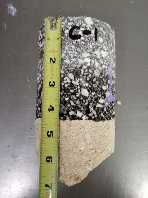
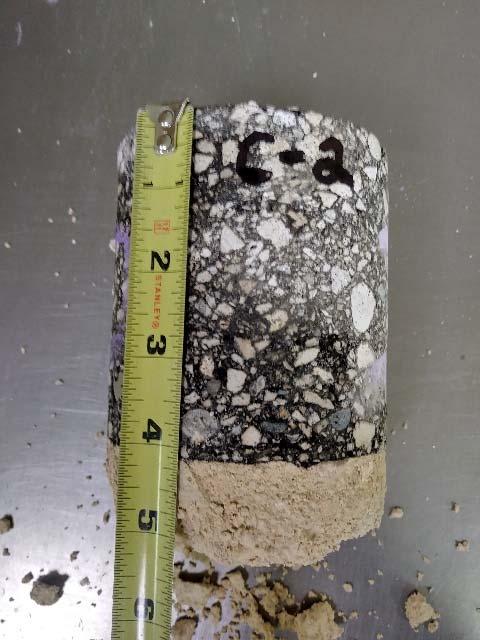
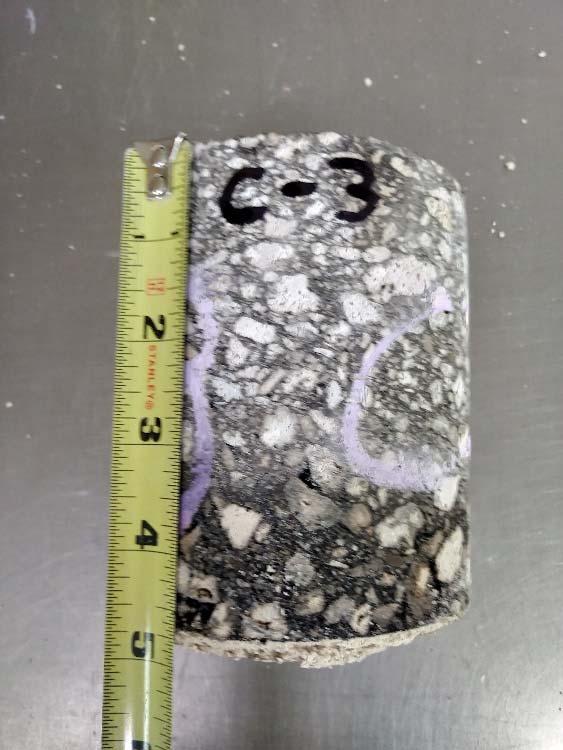
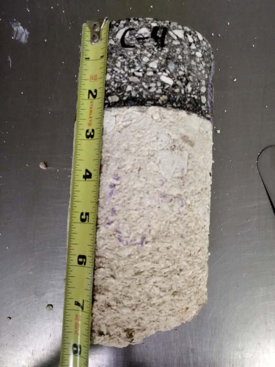
53 CORE CORE CORE CORE