Planning, Development & Facilities 349 Magnolia Avenue Glendale, California Tel: Fax: TRANSMITTAL
|
|
|
- Abner Harris
- 5 years ago
- Views:
Transcription

1 Planning, Development & Facilities 49 Magnolia Avenue Glendale, California 904 Tel: Fax: Project Name: Jefferson ES- Classroom Bldg DSA No: A#:0-46, File#:9-4 District PO No: District Contract No: -5/6 TRANSMITTAL To: Tony Barrios From: Chalmers Construction Services Inc. TR No. Date: 0 04/8/6 We are Sending You: Via: These are Transmitted as Checked Below: Submittals For Approval No Exceptions Taken Prints Mail For Your Use Make Corrections Noted Tracings Messenger As Requested Revise and Resubmit Specifications Hand For Review & Comment Rejected Samples Special Delivery Use/Distribution Other Copy of Letter Fax For Your Information Change Order Other Copies Date Doc. No. Description 04/8/6 Submittal # ( 059 ) Remarks: NO EXCEPTION TAKEN NOTE MARKINGS REJECTED REVISE AND RESUBMIT Review is for general conformance with the design concept and Contract Documents. If any deviations from the Contract Documents are included herein, such deviations shall be presumed by the Contractor as not having been reviewed, except where specific attention is called to the change as a deviation. Markings or comments shall not be construed as relieving the Contractor from compliance with the project plans and specifications. The Contractor is responsible for details and accuracy; confirming and correlating all quantities and dimensions; fabrication processes and techniques of construction; coordination of this work with that of all other trades and the satisfactory performance of this work. Issued By: Ara Baghdasarians Copies To:. By Teagan Castellon May 0, 06

2 H. L. Moe Co., Inc. MOE-MOE-MOE-MOE-MOE-MOE-MOE-MOE-MOE-MOE-MOE-MOE-MOE-MOE-MOE-MOE-MOE-MOE-MOE-MOE-MOE-MOE-MOE-MOE-MOE-MOE-MOE-MOE-MOE-MOE-MOE-MOE-MOE-MOE-MEO-MOE-MOE-MOE-MOE-MOE-MOE-MOE-MOE-MOE-MOE-MOE-MOE Submittal Package for Thomas Jefferson Elementary School Glendale, CA Division Plumbing Submitter: H. L. Moe Co., Inc. Date: April 8, 06 Submittal No: 04 Hangers & Supports for Plumbing By: AR 56 Commercial St. Glendale, CA FAX California State License No Since 9

3 Pllumbiing Submiittall Thomas Jefferson Elementary School MOE-MOE-MOE-MOE-MOE-MOE-MEO-MOE-MOE-MOE-MOE-MOE-MOE-MOE-MOE-MOE-MOE-MOE-MOE-MOE-MOE-MOE-MOE-MOE-MOE-MOE-MOE-MOE-MOE-MOE-MOE-MOE-MOE-MOE-MEO-MOE-MOE-MOE-MOE-MOE-MOE-MOE-MOE-MOE-MOE-MOE-MOE-MOE-MOE Page 05 9 Hangers & Supports for Plumbing PART PRODUCTS. HANGERS, SUPPORTS AND ANCHORS A. Hangers and Supports:. Adjustable Band Hanger and Felt Lined: Cooper B Line 0/0F, Anvil 69/69F. Clevis Hanger: Cooper B Line B00, Anvil 60. Riser Clamp: Cooper B Line/F, Anvil 6 4. Channel: Cooper B Line B4, Unistrut 5. Pipe Clamps: Cooper B Line B000, Anvil AS 00 Series 6. Cushion Clamps: Cooper B Line BVT/BVP,. Deck Inserts: Tolco 09, 0/0N, Blue Banger Hanger BBMD, BBRD 8. Thread Rod: Cooper B Line ATR, Anvil Wedge Anchors: Thunderstud Wedge Anchor, Simpson Strong Bolt 0. Sway Bracing: Cooper B Line 90/909/000. Rooftop Pipe Supports: Cooper B Line Dura Block DB-5 John Soler 05/0/06 Sub. No.: 0 Page of
 Size Range: / (65mm) thru 8 (00mm) pipe Material: Steel Available in stainless steel Function: Recommended for the suspension of noninsulated pipe or insulated pipe with B5 shield.")

4 . A - Adjustable Band Hangers Pipe Hangers B0 - Adjustable Band Hanger (TOLCO Fig. ) B0F - Adjustable Band Hanger Felt Lined (TOLCO Fig. F) Size Range: / (65mm) thru 8 (00mm) pipe Material: Steel Available in stainless steel Function: Recommended for the suspension of noninsulated pipe or insulated pipe with B5 shield. Approvals: Conforms to Federal Specification WW-H-E & A-A-9A, Type 0 and Manufacturers Standardization Society ANSI/MSS SP-69 & SP-58, Type 0. Standard Finish: Pre-Galvanized Order By: Figure number and finish. B Center of pipe to top of knurled hanger rod nut. C Rod Take-Out Center of pipe to bottom of hanger rod. D Top of pipe to bottom of hanger rod nut. B D A (Rod Size) Hanger Rod Not Included C B0F B0 Nominal Rod Size B C D Part No. Pipe Size A (mm) (mm) (mm) B0- / /" (65) /"- 4" (0.6) 5 /8" (66.) 9 /6" (9.) B0- " (5) /"- 4 /" (4.) /8" (9.4) 5 /8" (4.) B0- / /" (90) /"- 4 5 /6" (5.4) 9 /6" (90.5) /6" (46.0) B0-4 4" (00) 5 /8"- 5 /6" (.8) 5 /8" (9.) 5 /8" (4.) B0-5 5" (5) 5 /8"- 5 5 /" (46.8) 4 /8" (04.8) 5 /8" (4.) B0-6 6" (50) /4"-0 " (.8) 5 /6" (8.6) " (50.8) B0-8 8" (00) /4"-0 8" (0.) 6 5 /6" (60.) /" (6.5) Pipe Hangers Max. Rec. Load Approx. Wt./00 Part No. lbs. (kn) lbs. (kg) B0- / 00 (.) 9 (.) B0-00 (.) 4 (5.4) B0- / 00 (.) 4 (9.0) B (.) 54 (4.5) B (.) 9 (44.0) B (4.) (5.) B (4.) 40 (6.5) All dimensions in charts and on drawings are in inches. Dimensions shown in parentheses are in millimeters unless otherwise specified. 59 Page.
 B0CTC - Adjustable Swivel Hanger for Copper Tubing - Plastic Coated Size Range: / (5mm) thru 6 (50mm) copper tubing Material: Steel Function: Recommended for the suspension of copper tubing,")
 Approvals: Conforms to Federal Specification WW-H-E & A-A-9A, Type 0 and Manufacturers Standardization Society ANSI/MSS SP-69 & SP-58, Type 0.")
5 Pipe Hangers B0CT - Adjustable Swivel Hanger for Copper Tubing (TOLCO Fig. 0) B0CTC - Adjustable Swivel Hanger for Copper Tubing - Plastic Coated Size Range: / (5mm) thru 6 (50mm) copper tubing Material: Steel Function: Recommended for the suspension of copper tubing, allowing for vertical adjustment. (Available with plastic coating to provide additional separation between tubing and hanger.) Approvals: Conforms to Federal Specification WW-H-E & A-A-9A, Type 0 and Manufacturers Standardization Society ANSI/MSS SP-69 & SP-58, Type 0. Standard Finish: DURA-COPPER Order By: Figure number and finish. B Center of pipe to top of knurled hanger rod nut. C Rod Take-Out Center of pipe to bottom of hanger rod. D Top of pipe to bottom of hanger rod nut. B D A (Rod Size) Hanger Rod Not Included C Nominal Rod Size B C D Part No. Pipe Size A (mm) (mm) (mm) Pipe Hangers B0CT- / /" (5) /8"-6 /6" (5.4) /8" (8.6) /" (4.6) B0CT- /4 /4" (0) /8"-6 5 /6" (58.) 5 /6" (.) /" (6.) B0CT- " (5) /8"-6 /" (6.5) 9 /6" (9.) 5 /" (9.) B0CT- /4 /4" () /8"-6 /" (6.5) 9 /6" (9.) " (5.4) B0CT- / /" (40) /8"-6 5 /6" (4.6) " (50.8) 5 /6" (.) B0CT- " (50) /8"-6 /8" (9.4) /8" (54.0) /6" (0.) B0CT- / /" (65) /"- 4 /6" (0.) 9 /6" (65.) /8" (4.9) B0CT- " (5) /"- 5 /6" (00.0) /4" (95.) /4" (.) B0CT- / /" (90) /"- 4 /6" (.) /4" (8.5) /" (8.) B0CT-4 4" (00) /"- 4 /6" (9.) 9 /6" (89.6) 9 /6" (9.) B0CT-5 5" (5) /"- 5 5 /6" (50.8) 4 5 /6" (09.5) 5 /" (45.) B0CT-6 6" (50) /"- 6 /6" (69.9) 5 /6" (.8) /8" (54.0) Max. Rec. Load Approx. Wt./00 Part No. lbs. (kn) lbs. (kg) B0CT- / 80 (0.80) 8 (6.6) B0CT- /4 80 (0.80) 0 (4.5) B0CT- 80 (0.80) 0 (4.5) B0CT- /4 80 (0.80) (5.4) B0CT- / 80 (0.80) (5.4) B0CT- 80 (0.80) (5.4) B0CT- / 00 (0.89) (4.0) B0CT- 50 (.) (4.9) B0CT- / 00 (.) 9 (.) B0CT-4 60 (.60) 40 (8.) B0CT (.) 95 (4.) B0CT-6 60 (.80) 8 (5.5) B0CT B0CTC All dimensions in charts and on drawings are in inches. Dimensions shown in parentheses are in millimeters unless otherwise specified. 60 Page.

6 COPPER TUBING HANGERS. A - Adjustable Band Hangers Fig. 69 Adjustable Swivel Ring, Tapped Per NFPA Standards Size Range: " through 4" Material: Carbon steel Finish: Copper plated, also available in yellow dichromate. Service: Recommended for suspension of non-insulated stationary copper tube. Approvals: Complies with Federal Specification A-A-9A (Type 0) WW-H--E (Type 0) and MSS-SP-69 (Type 0). Features: Threads are countersunk so that they cannot become burred or damaged. Knurled swivel nut provides vertical adjustment after piping is in place. Captured swivel nut will not fall off. Ordering: Specify nominal tube size, figure number, name and finish. Note: Metric nut available upon request. F C B F C B C L " through 4" Pipe C L " through 4" Pipe Tube Size Max Load Fig. CT-69: Loads (lbs) Weight (lbs) Dimensions (in) Weight B C F Note: Reflects changes in rod diameter from previously published data per recent revisions in MSS-SP-58 & 69 PH 4 Page.

7 COPPER TUBING HANGERS Fig. 69F Adjustable Swivel Ring, Felt Lined Size Range: " through 6" copper tube Material: Carbon steel and felt with adhesive backing Finish: Galvanized Service: Recommended for suspension of non-insulated stationary copper tubing. Maximum Temperature: 0 F Approvals: Complies with Federal Specification A-A-9A (Type 0), WW-H--E (Type 0), ANSI/MSS SP-69 and MSS SP-58 (Type 0). Features: The layer of felt separates the copper tubing from the steel ring for electrolytic resistance and also minimizes noise and vibration. Threads are countersunk so they cannot become burred or damaged. Knurled swivel nut provides vertical adjustment after tubing is in place. The captured nut is permanent in the bottom portion of band, allowing the hanger to be opened during installation if desired, but not allowing the nut to fall out. Ordering: Specify felt ring size, figure number and name. A C L /" & /4" tube /" through " Felted Ring A F G C B C L " through 6" tube /4" through 6" Felted Ring F C G B Felt lined Ring: IPS Sizing Dimensions (in) Pipe Size Felted Ring Size Tube Size Felted Ring Size Fig. 69F: Loads (lbs) Weight (lbs) Dimensions (in) Max Load Rod Size A B C F G Width / / , Weight Project: Address: Contractor: Engineer: PROJECT INFORMATION APPROVAL STAMP q Approved q Approved as noted q Not approved Remarks: Submittal Date: Notes : Notes : PH-. Page.4
8 . A - Clevis Hangers Pipe Hangers Fig. B00 - Standard Clevis Hanger (TOLCO Fig.) Size Range: / (5mm) to 6 (900mm) Material: Steel Function: Recommended for the suspension of non-insulated pipe or insulated pipe with a B5 shield. Note: When an oversized clevis is used, a pipe spacer should be placed over the cross bolt to assure that the lower U-strap will not move in on the bolt. When attaching seismic bracing to the clevis hangers, a B00PS (cross bolt spacer) must be installed. See Seismic Restraints Approval Guidelines. Order pipe sleeves Fig. CBS-(pipe size) separately. Approvals: Underwriter's Laboratories Listed in the USA (UL) and Canada (cul) for sizes /" (5) thru " (00). Factory Mutual Engineering Approved (FM) for /4 (0mm) thru 8 (00mm) pipe. Conforms to Federal Specification WW-H-E & A-A-9A, Type and Manufacturers Standardization Society ANSI/MSS SP-69 & SP-58, Type. Also available to accommodate rod schedule per per National Fire Protection Association (NFPA) Pamphlet. Maximum Temperature: 650 F (4 C). Standard Finish: Plain, Electro-Galvanized, DURA-GREEN, or Hot-Dip Galvanized also available in Stainless Steel Order By: Figure number and finish. For AWWA - Ductile Iron Clevis Hangers, see B0, page 50. ** Note: Do not use the dimensions shown in the B00 chart for NFPA hanger sizes. Contact Cooper B-Line for NFPA rod sizing on / (5mm) thru (00mm) pipe. Part numbers will be NFPA-pipe size. E Adjustment F Design Load Approx. Wt./00 Part No. (mm) (mm) Lbs. (kn) Lbs. (kg) B00- / /" (6.5) /6" (.) 0 (.5) 5 (.) B00- /4 /" (6.5) /" (.) 0 (.5) 9 (.) B00- /" (6.5) 5 /8" (5.9) 0 (.5) 5 (5.9) B00- /4 /" (6.5) /8" (.) 0 (.5) 40 (8.) B00- / /" (6.5) /6" (0.) 0 (.5) 4 (9.0) B00- * /" (6.5) 5 /8" (4.) 0 (.5) 5 (.6) B00- / * /" (6.5) " (50.8) 50 (6.00) 90 (40.8) B00- * /" (6.5) " (50.8) 50 (6.00) 0 (49.9) B00- / /" (6.5) " (50.8) 50 (6.00) 4 (64.4) B00-4 * /" (6.5) " (50.8) 40 (6.6) (59.9) Pipe Hangers B00-5 * /" (6.5) " (50.8) 40 (6.6) 5 (9.5) B00-6 * " (6.) " (50.8) 940 (8.6) 0 (45.) B00-8 /" (88.9) 5 /6" (58.) 000 (8.89) 485 (0.0) B00-0 /" (88.9) 5 /6" (58.) 600 (6.0) 846 (8.) B00- /" (88.9) 5 /8" (66.) 800 (6.90) 08 (49.) B00-4 4" (0.6) /8" (.0) 400 (8.68) 4 (649.5) B00-6 4" (0.6) /6" (68.) 4600 (0.46) 00 (99.9) B /" (4.) 5 /6" (00.0) 4800 (.5) 500 (4.0) B00-0 5" (.0) 5 /8" (6.5) 4800 (.5) 4400 (995.8) B00-4 5" (.0) 5 /8" (6.5) 4800 (.5) 5000 (68.0) B00-0 5" (.0) 6 /4" (58.) 6000 (6.69) 6600 (99.) B00-6 5" (.0 5 /6" (8.) 6000 (6.69) 844 (84.8) *SLIDE-RITE Clevis Hanger design, as shown above, for sizes, /,, 4, 5 & 6. All dimensions in charts and on drawings are in inches. Dimensions shown in parentheses are in millimeters unless otherwise specified. 49 Page.5
 Size Range: / (5mm) to 8 (00mm) pipe Material: Steel Insulation Material: /6 (4.")
 and Canada (cul). Maximum Temperature: 650 F (4 C).")
9 Pipe Hangers Fig. B00C - Standard Clevis Hanger - Plastic Coated (TOLCO Fig.PVC) Fig. B00F - Standard Clevis Hanger - Felt Lined (TOLCO Fig.F) Size Range: / (5mm) to 8 (00mm) pipe Material: Steel Insulation Material: /6 (4.8mm) Felt Service: The B00F is designed for the suspension of copper tube so as to prevent electrolysis between tubing and hanger. The B00C is designed for steel or other pipe types of the same O.D. Both B00F and B00C act to reduce noise and vibration in pipe or tubing systems. Approvals: Underwriter's Laboratories Listed in the USA (UL) and Canada (cul). Maximum Temperature: 650 F (4 C). Standard Finish: Plain, Electro-Galvanized, or Hot-Dip Galvanized. Contact Cooper B-Line for alternative finishes and materials. Order By: Figure number and finish. D E A (Rod Size) Hanger Rod Not Included C B Bottom of pipe to top of hanger. C Center of pipe to top of hanger. D Rod Take-Out Center of pipe to bottom of hanger rod. E Minimum thread length of hanger rod F Adjustment Top of cross bolt to bottom of hanger rod nut inside the hanger. B Pipe Size Rod Size B C D Part No. (mm) A (mm) (mm) (mm) Pipe Hangers B00- / /" (5) /8"-6 /8" (54.0) /6" (4.9) 5 /6" (.8) B00- /4 /4" (0) /8"-6 /6" (6.9) /8" (4.6) /8" (8.6) B00- " (5) /8"-6 /6" (.4) /8" (54.0) /8" (4.9) B00- /4 /4" () /8"-6 /6" (8.) 9 /6" (65.) /6" (46.0) B00- / /" (40) /8"-6 4" (0.6)` " (6.) /4" (5.) B00- " (50) /8"-6 4 /" (4.) /4" (8.5) /" (6.5) B00- / /" (65) /"- 5 9 /6" (4.) 4" (0.6) /6" (.8) B00- " (80) /"- 6 /4" (.4) 4 /8" (.8) 5 /6" (00.0) B00- / /" (90) /"- " (.8) 5" (.0) 4 /6" (0.) B00-4 4" (00) 5 /8"- /6" (98.4) 5 /" (9.) 4 /8" (.) B00-5 5" (5) 5 /8"- 9 /6" (0.) 6 /8" (55.6) 5" (.0) B00-6 6" (50) /4"-0 0 /6" (65.) 6 5 /6" (6.) 5 /6" (44.5) B00-8 8" (00) /4"-0 /4" (.8) 8 /8" (.) /8" (8.0) E Adjustment F Design Load Approx. Wt./00 Part No. (mm) (mm) Lbs. (kn) Lbs. (kg) B00- / /" (6.5) /6" (.) 0 (.5) 5 (.) B00- /4 /" (6.5) /" (.) 0 (.5) 9 (.) B00- /" (6.5) 5 /8" (5.9) 0 (.5) 5 (5.9) B00- /4 /" (6.5) /8" (.) 0 (.5) 40 (8.) B00- / /" (6.5) /6" (0.) 0 (.5) 4 (9.0) B00- /" (6.5) 5 /8" (4.) 0 (.5) 5 (.6) B00- / /" (6.5) " (50.8) 50 (6.00) 90 (40.8) B00- /" (6.5) " (50.8) 50 (6.00) 0 (49.9) B00- / /" (6.5) " (50.8) 50 (6.00) 4 (64.4) B00-4 /" (6.5) " (50.8) 40 (6.6) (59.9) B00-5 /" (6.5) " (50.8) 40 (6.6) 5 (9.5) B00-6 " (6.) " (50.8) 940 (8.6) 0 (45.) B00-8 /" (88.9) 5 /6" (58.) 000 (8.89) 485 (0.0) B00C B00F All dimensions in charts and on drawings are in inches. Dimensions shown in parentheses are in millimeters unless otherwise specified. 5 Page.6

10 CLEVIS HANGERS Fig. 60. A - Clevis Hangers Adjustable Clevis Hanger Size Range: " through 0" Material: Carbon steel Finish: q Plain, q Galvanized, or q Primed, also available in q Plastic or q Epoxy Coated Service: Recommended for the suspension of stationary pipe lines. Maximum Temperature: Plain 650 F, Galvanized and Epoxy 450 F Approvals: Complies with Federal Specification A-A-9A (Type ), WW-H--E (Type ), ANSI/MSS SP-69 and MSS SP-58 (Type ). UL (Sizes /4" through 8"), ULC Listed (Sizes /4" through 4") and FM Approved (Sizes 4" through 8"). Installation: Hanger load nut above clevis must be tightened securely to assure proper hanger performance. Adjustment: Vertical adjustment without removing pipe may be made from through 5, varying with the size of clevis. Tighten upper nut after adjustment. Features: Design has yoke on outside of lower U-strap so yoke cannot slide toward center of bolt, thus bending of bolt is minimized. Sizes 5" and up have rod and two nuts instead of bolt and nut; thread length on clevis rod is such that the thread locks the nuts in place, and threads are not in shear plane. Ordering: Specify pipe size, figure number, name and finish. Notes: Punched forming holes may be present on certain sizes of this clevis hanger. These holes are solely for the purpose of manufacturing, and do not effect the structural integrity or load carrying capacities of these hangers. For insulated line options without shields, see Figures 60 ISS and Figure 00. For insulated line options with shields, see Figures 6 and 68. For ductile iron pipe sizes, see Figure 590. Caution: When an oversize clevis is used, a pipe spacer or multispacer should be placed over clevis bolt to ensure that the lower U-strap will not move in on the bolt. E H E H G G C L Pipe Size /" to /4" C L Pipe Sizes " and Larger F A A F B C B C Pipe Size Fig. 60: Loads (lbs) Weights (lbs) Dimensions (in) Max Load Span Ft. Weight Rod Size A B 6 C Rod Take Out E Adjust. F G H Width Lower * * * * ,50 * * /4 4 4*.5, * /6 6,940 * ,000 9* /6 0,600 * /4 8,800 * ,00 5* , , / 0 4, , , Span represents the maximum recommended distance between hangers on a continuous and straight run of horizontal standard weight steel pipe filled with water. In all cases, verify that chosen location of hangers does not subject hangers to a load greater than the maximum recommended load shown above. *Indicates that span represents the maximum span for water filled pipe as given in Table of page 5. Project: Address: Contractor: Engineer: Submittal Date: Notes : Notes : PH-. PROJECT INFORMATION Page. APPROVAL STAMP q Approved q Approved as noted q Not approved Remarks:
 Size Range: (B) /\" (5mm) thru 0\" (60mm) pipe (BF) /\" (5mm) thru /\" (65mm) copper tubing (BC) /\" (5mm) thru 6\" (50mm) pipe Material: Steel Insulation Material: (Fig. 6F) /6\" (4.8mm) felt.")
 thru 8\" (00mm). Conforms to Federal Specification WW-H-E & A-A-9A, Type 8, and Manufacturers Standardization Society ANSI/MSS SP-69 & SP-58, Type 8.")
 (mm) Bolt Size Lbs.")
 /8\"-6 x /4\" 55 (.) (50.9) B- / /\" (40) 0 /4\" (60.) /8\"-6 x /\" 55 (.) (5.) B- \" (50) 0 /4\" (.0) /8\"-6 x /\" 55 (.) 65 (5.0) B- / /\" (65) /4\" (85.) /8\"-6 x /\" 90 (.) 80 (8.6) B- \" (80) 5 /6\" (0.")
11 . A - Riser Clamps Fig. B - Standard Riser Clamp (TOLCO Fig. 6) Fig. BF - Felt Lined Standard Riser Clamp (TOLCO Fig. 6F) Fig. BC - PVC Coated Standard Riser Clamp (TOLCO Fig. 6PVC) Size Range: (B) /" (5mm) thru 0" (60mm) pipe (BF) /" (5mm) thru /" (65mm) copper tubing (BC) /" (5mm) thru 6" (50mm) pipe Material: Steel Insulation Material: (Fig. 6F) /6" (4.8mm) felt. Function: Used for supporting vertical piping. Approvals: Underwriters Laboratories Listed in the USA (UL), Canada (cul) /4" (0mm) - 8" (00mm). Factory Mutual Engineering Approved, /4" (0mm) thru 8" (00mm). Conforms to Federal Specification WW-H-E & A-A-9A, Type 8, and Manufacturers Standardization Society ANSI/MSS SP-69 & SP-58, Type 8. Maximum Temperature: 650 F (4 C) Finish: Pla Contact Cooper B-Line for alternative finishes and materials. Order By: (B and BC) pipe size and finish. (BF) copper tube size and finish. BF is available for Iron Pipe Size, consult factory. Design Load Bolt Size L Bolts and Nuts Included Pipe Clamps BC BF Pipe Size L Design Load Approx. Wt./00 Part No. (mm) (mm) Bolt Size Lbs. (kn) Lbs. (kg) B- / /" (5) 9" (8.6) /8"-6 x /4" 55 (.) 0 (45.9) B- /4 /4" (0) 9 /4" (4.9) /8"-6 x /4" 55 (.) 05 (4.) B- " (5) 9 9 /6" (4.9) /8"-6 x /4" 55 (.) 09 (49.4) B- /4 /4" () 0" (54.0) /8"-6 x /4" 55 (.) (50.9) B- / /" (40) 0 /4" (60.) /8"-6 x /" 55 (.) (5.) B- " (50) 0 /4" (.0) /8"-6 x /" 55 (.) 65 (5.0) B- / /" (65) /4" (85.) /8"-6 x /" 90 (.) 80 (8.6) B- " (80) 5 /6" (0.) /8"-6 x /" 50 (.5) 95 (88.4) B- / /" (90) /8" (4.) /"- x /4" 60 (.98) (98.5) B-4 4" (00) /8" (.0) /"- x /4" 80 (.60) 8 (0.5) B-5 5" (5) 4" (55.6) /"- x /4" 60 (5.6) 480 (.) B-6 6" (50) 5 /6" (85.8) /"- x " 50 (6.98) 56 (8.6) B-8 8" (00) /4" (450.8) 5 /8"- x /" 500 (.) 95 (44.) B-0 0" (50) 9 /6" (49.) 5 /8"- x /" 500 (.) 0 (499.4) B- " (00) /6" (550.9) 5 /8"- x " 00 (.0) 6 (5.) B-4 4" (50) 9 /6" (598.5) 5 /8"- x " 00 (.0) (85.6) B-6 6" (400) 6 /8" (669.9) /4"-0 x /4" 900 (.90) 959 (4.) B-8 8" (450) 8 /8" (.4) /4"-0 x /4" 900 (.90) 5 (46.4) B-0 0" (500) 0 /8" (84.) /4"-0 x /" 900 (.90) 568 (68.4) B-4 4" (600) 4 /8" (885.8) /4"-0 x /" 900 (.90) 4064 (84.) B-0 0" (50) 40 /4" (05.0) /8"-9 x /" 900 (.90) 606 (8.8) Notes: For ductile iron (D.I.) pipe use part number BCI-pipe size. Contact B-Line Engineering for more information. Pipe Clamps All dimensions in charts and on drawings are in inches. Dimensions shown in parentheses are in millimeters unless otherwise specified. 5 Page.8

12 STEEL PIPE CLAMPS Fig. 6. A - Riser Clamps Extension Pipe or Riser Clamp Size Range: 4" through 4" Material: Carbon steel Finish: q Plain, q Galvanized or q Epoxy coated Service: For support of stationary steel pipe risers, cast iron pipe or conduit. This product is not intended for use with hanger rods. For this application refer to Fig. 40 Riser Clamp, page 4. Maximum Temperature: Plain 650 F, Galvanized and Epoxy 450 F Approvals: Complies with Federal Specification A-A-9A (Type 8) WW-H--E (Type 8), ANSI/MSS SP-69 and MSS SP-58 (Type 8). UL, ULC Listed (Sizes " - 8"). Installation: Clamp is fitted and bolted preferably below a coupling, hub or welded lugs on steel pipe. Bolt torques should be per industry standards (see page ). Clamp is designed for standard steel pipe O.D. and this must be considered in sizing the riser for other types of piping. Ordering: Specify pipe size, figure number, name and finish. Pipe Size Fig. 6: LOAds (lbs) Weight (lbs) Dimensions (in) TORQUE (FT-LBS) Max Load Weight L G Width Note: Refer to Technical Data Section for cast iron soil pipe data. B C Bolt Diameter Torque Values , , , , , , C L B L C G Project: Address: Contractor: Engineer: Submittal Date: Notes : Notes : PH-. PROJECT INFORMATION Page.9 APPROVAL STAMP q Approved q Approved as noted q Not approved Remarks:
13 . A - Channel B4 Channel & Combinations B4 Thickness: 4 Gauge (.9 mm) Standard lengths: 0 (.05 m) & 0 (6.09 m) Standard finishes: Plain, Dura-Green, Pre-Galvanized, Hot-Dipped Galvanized, Stainless Steel Type 04 or 6, Aluminum Weight:.40 Lbs./Ft. (.08 kg/m) 5 /8 (4.) /8 (9.5) X /6 (0.6) 5 /8 (4.) /8 (.) Y Y X /8 (9.5).04 (8.6) 9 / (.) Channel & Combinations SECTION PROPERTIES X - X Axis Y - Y Axis Areas of Moment of Section Radius of Moment of Section Radius of Channel Weight Section Inertia (I) Modulus (S) Gyration (r) Inertia (I) Modulus (S) Gyration (r) lbs./ft. kg/m sq. cm 4 cm 4 cm cm 4 cm 4 cm cm B4.44 (.5).44 (.4).494 (6.).60 (.4).594 (.5).85 (.).86 (.5).66 (.68) B4A.884 (4.9).848 (5.4).54 (.8).464 (.58).94 (.9). (5.45).450 (.49).66 (.68) Calculations of section properties are based on metal thicknesses as determined by the AISI Cold-Formed Steel Design Manual. X Y X /4 (8.5) X Y X /4 (8.5) X Y 5 /8 (4.) X /4 (8.5) /6 (0.6) Y 5 /8 (4.) 5 /8 (4.) B4A Wt..80 Lbs./Ft. (4.6 kg/m).0 Y 5 /8 (4.) (8.6) 5 /8 (4.) B4B Wt..80 Lbs./Ft. (4.6 kg/m) /6 (0.6) Y 5 /8 (4.) B4C Wt..80 Lbs./Ft. (4.6 kg/m) Reference page 4 for general fitting and standard finish specifications. 4 Page.0
14 B4 Beam & Column Loading Data BEAM LOADING Uniform Deflection = Beam Span Channel Uniform Load and Deflection /40 Span /60 Span In. mm Style Lbs. N In. mm Lbs. N Lbs. N (05) B4 50 (84).04 (.5) 50 (84) 50 (84) B4A 50* (84).00 (.05) 50* (84) 50* (84) 4 (609) B4 9 (64).05 (.45) 9 (64) 9 (64) B4A 50* (84).04 (.5) 50* (84) 50* (84) 6 (94) B4 99 (4088).8 (.5) 99 (4088) 0 (0) B4A 50* (84).048 (.) 50* (84) 50* (84) 48 (9) B4 689 (065). (5.6) 60 (00) 405 (80) B4A 50* (84).5 (.9) 50* (84) 50* (84) 60 (54) B4 55 (45).55 (9.0) 89 (0) 59 (5) B4A 58 (65).95 (4.95) 58 (65) 94 (556) (89) B4 460 (046).5 (.98) 0 (0) 80 (800) B4A 65 (56).8 (.4) 65 (56) 898 (994) 84 () B4 94 (5).695 (.65) 98 (88) (58) B4A 084 (48).8 (9.) 990 (4404) 660 (96) 96 (48) B4 45 (54).908 (.06) 5 (66) 0 (449) B4A 949 (4).500 (.0) 58 () 505 (46) 08 (4) B4 06 (6).49 (9.8) 0 (54) 80 (56) B4A 84 (50).6 (6.08) 599 (664) 99 (5) 0 (048) B4 6 (8).49 (6.04) 9 (4) 65 (89) B4A 59 (6).8 (9.86) 485 (5) (4) Based on simple beam condition using an allowable design stress of 5,000 psi ( MPa) in accordance with MFMA, with adequate lateral bracing (see page for further explanation). Actual yield point of cold rolled steel is 4,000 psi. To determine concentrated load capacity at mid span, multiply uniform load by 0.5 and corresponding deflection by 0.8. *Failure determined by weld shear. COLUMN LOADING Max. Column Loading K =.80 Max. Column Loading C.G.) Unbraced Channel Loaded@ Loaded@ Height Style C.G. Slot Face K =.65 K =.0 K =. In. mm Lbs. N Lbs. N Lbs. N Lbs. N Lbs. N (05) 4 (609) 6 (94) 48 (9) 60 (54) (89) 84 () 96 (48) 08 (4) 0 (048) B4 644 (865) 0 (68) 6509 (895) 60 (85) 698 (50) B4A (580) 4988 (88) (5888) (5858) (5865) B4 584 (69) 896 (88) 64 (4) 548 (489) 508 (40) B4A 99 (596) 494 (90) 09 (586) 88 (506) 6 (566) B4 508 (40) 69 (650) 555 (46) 40 (96) 56 (5640) B4A 6 (566) 489 (46) 85 (564) 56 (545) 804 (550) B4 404 (984) (006) 4800 (5) 008 (80) 4 (0) B4A 5 (5890) 465 (095) 5 (55656) 456 (50959) 065 (48) B4 008 (80) 8 (8) 98 (695) 00 (986) 40 (40) B4A 456 (50959) 400 (88) 08 (55) 04 (468) 969 (4086) B4 4 (0) 56 (6948) (89) 40 (40) 9 (64) B4A 065 (48) 048 (558) 546 (559) 969 (4086) 58 (0) B4 898 (844) 40 (5960) 50 (9) 444 (64) 68 (595) B4A 900 (448) 6 (0506) 098 (48565) 68 (45) 5464 (405) B4 608 (5) 5 (56) 089 (99) 6 (5498) 000 (4448) B4A 860 (86) 866 (800) 094 (4545) 604 (696) 484 (86) B4 9 (64) 046 (465) 96 (989) 08 (495) 80** (80) B4A 58 (0) 498 (666) 9 (469) 460 () 06 (406) B4 6 (5498) 94 (490) 58 (09) 95** (49) 64** (98) B4A 604 (696) 6 (5409) 8455 (60) 856 (5) 6** (908) **Where the slenderness ratio KL exceeds 00, and K = end fixity factor, L = actual length and r = radius of gyration. r Reference page 4 for general fitting and standard finish specifications. Channel & Combinations 5 Page.
15 . A - Channel 5 CHANNEL Channel Selection Chart... P000 ( Gauge) P00 (4 Gauge) P000 (6 Gauge) P000 ( Gauge) P00 ( Gauge) P4000 (6 Gauge) P400 (4 Gauge) P4400 ( Gauge) P450 ( Gauge) P5000 ( Gauge) P5500 ( Gauge) Closure Strips...60 End Caps and Frame Caps...6 Lateral Bracing Load Reduction Chart & Bearing Loads...6 MATERIAL Unistrut channels are accurately and carefully cold formed to size from low-carbon strip steel. All spot-welded combination members, except P00T, are welded " (6 mm) maximum on center. STEEL: PLAIN Ga. (. mm), 4 Ga.(.9 mm) and 6 Ga. (.5 mm) ASTM A0 SS GR. STEEL: PRE-GALVANIZED Ga. (. mm), 4 Ga. (.9 mm) and 6 Ga. (.5mm) ASTM A65 GR. For other materials, see Special Metals or Fiberglass sections. FINISHES All channels are available in: ASTM A65 G90. ASTM A. DIMENSIONS Imperial dimensions are illustrated in inches. Metric dimensions are shown in millimeters and rounded to one decimal place. STANDARD LENGTHS Standard lengths are 0 feet (.05m) and 0 feet (6.0m). Tolerances are ± ( mm). Special lengths are available for a small cutting charge with a tolerance of ± ( mm). CURVED CHANNEL Contact your local Unistrut Service Center or Unistrut Corporation for more information. LOAD DATA All beam and column load data pertains to carbon steel and stainless steel channels. Load tables and charts are constructed to be in accordance with the SPECIFICATION FOR THE DESIGN OF COLD-FORMED STEEL STRUCTURAL MEM- BERS 00 EDITION published by the AMERICAN IRON AND STEEL INSTITUTE USING ASD METHOD. Loads are based on ksi steel cold formed to 4 ksi. Type of Load Safety Factor to Yield Strength Safety Factor to Ultimate Strength Beam Loads.6.0 Column Load.80. Page.
16 Channel Pictorial Index 5 8" Channel P000 Series ( ga.) Concrete Inserts Electrical Fittings Pipe/Conduit Supports General Fittings Nuts & Hardware Telestrut P000 Pg 4 P00 Pg 0 P00 Pg 4 P00T Pg P00A Pg P4000 Pg 4 P00B Pg P00C Pg P00 Pg P00 A Pg P00 B Pg P004A Pg P00 C Pg P00 D Pg P00 C4 Pg P00 Series (4 ga.) P000 Series (6 ga.) P000 Series ( ga.) P00 Series ( ga.) P400 Series (4 ga.) P400 Pg 45 P40 Pg 45 P0 Pg 0 P0A Pg 0 P0B Pg 0 P4000 Series (6 ga.) P400 Pg 4 End Caps and Frame Caps P860 Series Pg 6 P859 Pg 6 P400 Pg 4 P80 Pg 6 P4004 Pg 4 P0C Pg 0 P80 A, P80 A Pg 6 A000 Series (4 gauge) 4" Channel A000 Pg A00 Pg A00A Pg A00B Pg P6000 Series (9 gauge) 6" Channel P000 Pg P4400 Series ( ga.) A00C Pg P4400 Pg 48 P440 Pg 48 P00 Pg P450 Series ( ga.) P80, P80 P480, P580, P5580 Pg 6 A00 Pg P450 Pg 5 P45 Pg 5 P00A Pg P40 P80, P80 Pg 6 P00B Pg A00 Series (4 gauge) 4" Channel A0 Pg P5000 Pg 54 P00C Pg P5000 Series ( ga.) P84 Pg 60 Alternate Framing Systems A4000 Pg 5 P500 Pg 54 P84P Pg 60 P000 Pg 6 P5500 Pg 5 A400 Pg 5 P00 Pg 6 P5500 Series ( ga.) 5 Channel Closure Strips P84 Pg 60 A4000 Series (9 gauge) 4" Channel P000 Series (9 gauge) 6" Channel P550 Pg 5 P84P Pg 60 P00 Pg 9 P84F Pg 60 A5000 Pg P900 Pg 65 P00 Pg P0 Pg 9 P9000 Series ( ga.) Telestrut Channel P9000 Pg 65 PP Pg 60 A5000 Series (4 gauge) 4" Channel Unipier Solar P6000 Pg 8 P600 Pg 8 P600A Pg 84 P600B Pg 84 P600C Pg 84 P000 Pg 85 P00 Pg 85 5 Framing System Page.
17 P000 & P00 Channels 5 8" Channel P " GR HG PG PL Telestrut Nuts & Hardware P ".0" Wt/00 Ft:89 Lbs (8 kg/00 m) Gauge Nominal Thickness.05" (.mm) GR HG PG PL Concrete Inserts Electrical Fittings Pipe/Conduit Supports General Fittings P000 DS P000 KO 4" Slots are 4" (69.9) x (.) " (88.9) on Center CHANNEL NUTS (REFER TO PAGES,4 FOR DETAILS) P000 H P000 SL 8.6 Wt/00 Ft: 8 Lbs (56 kg/00 m) Gauge Nominal Thickness.05" (.mm) P000 HS Wt/00 Ft: Lbs (5 kg/00 m) Wt/00 Ft: 5 Lbs (60 kg/00 m) Wt/00 Ft:85 Lbs (5 kg/00 m) (.) Knockouts 6" (5.4) on Center 4" (9.) Pipe Clamps can be Mounted on Both Sides 9 6" (4.) Dia. Holes (4.6) on Center Slots are " (6.) x " (0.) 4" (0.6) on Center " (.) GR HG PG PL GR HG PG PL P000 T 9 6" (4.) Dia. Holes (4.6) on Center Wt/00 Ft: 90 Lbs (8 kg/00 m) Wt/00 Ft: 85 Lbs (5 kg/00 m) Wt/00 Ft: 85 Lbs (5 kg/00 m) " (5.4) Slots are (8.6) x 9 6" (4.) " (50.8) on Center (.) GR HG PG PL GR HG PG PL 6" (0.) SEE PAGE, 4 Solar Unipier P P P P00 P008 P009 P00 UNISTRUT P008T P006T40 P00T Channel Finishes: PL, GR, HG, PG, ZD; Standard Lengths: 0' & 0' UNISTRUT P04 P0S P0S P0 P0 P04S P P P P00 P008 P009 P00 P06-06 P06-08 P06-04 P CORE PRODUCTS - TYPICALLY AVAILABLE FROM STOCK 5 Framing System Page.4
18 P000 Channel Combinations P00 T 5 (4.) 4" (8.6) P00 A 5 (4.) 4" (8.6) P00 B 5 (4.) 4" (8.6) 5 8" Channel P00 C 4" (8.6) 5 (4.).6" (4.6).5" (40.0).6".864" (9.) (.9) Wt/00 Ft: 8 Lbs (56 kg/00 m) Gauge Nominal Thickness.05" (.mm) P00 B 4 (.8).8" (9.8) Wt/00 Ft: Lbs (48 kg/00 m) Gauge Nominal Thickness.05" (.mm) 5 (4.) Wt/00 Ft: 566 Lbs (84 kg/00 m) Gauge Nominal Thickness.05" (.mm) P00 C4 4" (8.6) 5 Framing System 4" (8.6).84" (.5) Wt/00 Ft: 55 Lbs (,4 kg/00 m) Gauge Nominal Thickness.05" (.mm).09".96" (8.0) (.) Wt/00 Ft: 8 Lbs (56 kg/00 m) Gauge Nominal Thickness.05" (.mm) P00 4 (.8) Channel Finishes: PL, GR, HG, PG, ZD; Standard Lengths: 0' & 0' Wt/00 Ft: 566 Lbs (84 kg/00 m) Gauge Nominal Thickness.05" (.mm) P00 D 4" (8.6) Wt/00 Ft: 566 Lbs (84 kg/00 m) Gauge Nominal Thickness.05" (.mm) P00 C 4" (8.6).90" (49.0) 5 (4.) 4"(8.6) 4" (8.6).4" (6.8).40" (6.0).88" (5.).86" (4.).54" (4.4).896" (48.).0" (.5) Wt/00 Ft: 566 Lbs (84 kg/00 m) Gauge Nominal Thickness.05" (.mm) Page.5 Wt/00 Ft: 8 Lbs (56 kg/00 m) Gauge Nominal Thickness.05" (.mm) P00 A 4 (.8).8" (9.8) 5 (4.).84" (.5) Wt/00 Ft: 566 Lbs (84 kg/00 m) Gauge Nominal Thickness.05" (.mm) P00 Wt/00 Ft: Lbs (495 kg/00 m) Gauge Nominal Thickness.05" (.mm) P004 A 5 (4.) 4 64" (44.) " (46.8) 64" (0.6) 4" (0.6) 4 "(0.4) 6" (.) 4 (.8) 6" (.).45" (.6) Wt/00 Ft: 668 Lbs (994 kg/00 m) Gauge Nominal Thickness.05" (.mm).489 (.4 CORE PRODUCTS - TYPICALLY AVAILABLE FROM STOCK Unipier Solar Concrete Inserts Electrical Fittings Pipe/Conduit Supports General Fittings Nuts & Hardware Telestrut
19 P00 & P0 Channels Concrete Inserts Electrical Fittings Pipe/Conduit Supports General Fittings Nuts & Hardware Telestrut 5 8" Channel P00 5 P0 A 4" P0 C 4" 5.9".896"." " P00 KO.854".900".5" Wt/00 Ft: 84 Lbs (4 kg/00 m) 4 Gauge Nominal Thickness.05" (.9mm).666".584" Wt/00 Ft: 4 Lbs ( kg/00 m) 4 Gauge Nominal Thickness.05" (.9mm) P0 4" P0 B 4" Wt/00 Ft: 84 Lbs (4 kg/00 m) 4 Gauge Nominal Thickness.05" (.9mm) Wt/00 Ft: 84 Lbs (4 kg/00 m) 4 Gauge Nominal Thickness.05" (.9mm) Wt/00 Ft: 6 Lbs (0 kg/00 m) (.) Knockouts 6" (5.4) on Center P00 SL Slots are " (6.) x " (0.) 4" (0.6) on Center " (.) 5 P00 HS " (5.4) Wt/00 Ft: 84 Lbs (4 kg/00 m) 4 Gauge Nominal Thickness.05" (.9mm) 9 6" (4.) Dia. Holes (4.6) on Center P00 T 4. Slots are (8.6) x 9 6" (4.) " (50.8) on Center Wt/00 Ft: 40 Lbs (08 kg/00 m) Wt/00 Ft: 6 Lbs (0 kg/00 m) Wt/00 Ft: 6 Lbs (0 kg/00 m) CHANNEL NUTS (REFER TO PAGES,4 FOR DETAILS) SEE PAGE, 4 (.) 6" (0.) Solar Unipier P P P P00 P008 P009 P00 UNISTRUT P008T P006T40 P00T Channel Finishes: PL, GR, HG, PG, ZD; Standard Lengths: 0' & 0' UNISTRUT P04 P0S P0S P0 P0 P04S P P P P00 P008 P009 P00 P06-06 P06-08 P06-04 P CORE PRODUCTS - TYPICALLY AVAILABLE FROM STOCK 5 Framing System Page.6
20 P000 & P00 Channels P000 5 P00 A 4" 5 5.5".890" 9 ".890".5" Wt/00 Ft: 6 Lbs ( kg/00 m) 6 Gauge Nominal Thickness.060" (.5mm) Wt/00 Ft: Lbs (46 kg/00 m) 6 Gauge Nominal Thickness.060" (.5mm) P00 5 4" P00 B 5 4" Wt/00 Ft: Lbs (46 kg/00 m) 6 Gauge Nominal Thickness.060" (.5mm) 4. Wt/00 Ft: Lbs (46 kg/00 m) 6 Gauge Nominal Thickness.060" (.5mm) General Fittings Nuts & Hardware Telestrut 5 8" Channel P00 C 4" 5.664".586" ".85" 9..6 Wt/00 Ft: Lbs (46 kg/00 m) 6 Gauge Nominal Thickness.060" (.5mm) Wt/00 Ft: Lbs (68 kg/00 m) P000 KO (.) Knockouts 6" (5.4) on Center P000 SL Slots are " (6.) x " (0.) 4" (0.6) on Center P000 HS 9 6" (4.) Dia. Holes (4.6) on Center P000 T Slots are (8.6) x 9 6" (4.) " (50.8) on Center Pipe/Conduit Supports Electrical Fittings " (.) (.) Wt/00 Ft: Lbs (4 kg/00 m) Wt/00 Ft: Lbs (68 kg/00 m) Wt/00 Ft: Lbs (68 kg/00 m) CHANNEL NUTS (REFER TO PAGES,4 FOR DETAILS) SEE PAGE, 4 " (5.4) 6" (0.) Concrete Inserts P P P P00 P008 P009 P00 UNISTRUT P008T P006T40 P00T Channel Finishes: PL, GR, HG, PG, ZD; Standard Lengths: 0' & 0' UNISTRUT P04 P0S P0S P0 P0 P04S P P P P00 P008 P009 P00 P06-06 P06-08 P06-04 P06-40 Solar Unipier 5 Framing System Page.
21 P000 & P00 Channels 5 8" Channel P " Telestrut.84".59" Wt/00 Ft: 0 Lbs (5 kg/00 m) Gauge Nominal Thickness.05" (.mm) Nuts & Hardware P General Fittings 4" 69.9 Wt/00 Ft: 40 Lbs (506 kg/00 m) Gauge Nominal Thickness.05" (.mm) Pipe/Conduit Supports P000 HS 9 6" (4.) Dia. Holes (4.6) on Center P000 KO (.) Knockouts 6" (5.4) on Center P000 SL Slots are " (6.) x " (0.) 4" (0.6) on Center " (.) " (5.4) Electrical Fittings P000 T Wt/00 Ft: 65 Lbs (46 kg/00 m) Wt/00 Ft: 0 Lbs (5 kg/00 m) Slots are (8.6) x 9 6" (4.) " (50.8) on Center Wt/00 Ft: 65 Lbs (46 kg/00 m) Concrete Inserts (.) Wt/00 Ft: 65 Lbs (46 kg/00 m) 6" (0.) CHANNEL NUTS (REFER TO PAGES,4 FOR DETAILS) SEE PAGE, 4 Solar Unipier P P P P00 P008 P009 P00 UNISTRUT P008T P006T40 P00T Channel Finishes: PL, GR, HG, PG, ZD; Standard Lengths: 0' & 0' UNISTRUT P04 P0S P0S P0 P0 P04S P P P P00 P008 P009 P00 P06-06 P06-08 P06-04 P CORE PRODUCTS - TYPICALLY AVAILABLE FROM STOCK 5 Framing System Page.8
22 P00 & P0 Channels P ".60" 9 " Wt/00 Ft: 4 Lbs (00 kg/00 m) Gauge Nominal Thickness.05" (.mm) PL 5 8" Channel Telestrut P0 4" Nuts & Hardware P00 HS 9 6" (4.) Dia. Holes (4.6) on Center P00 T Wt/00 Ft: 69 Lbs (400 kg/00 m) Gauge Nominal Thickness.05" (.mm) Slots are (8.6) x 9 6" (4.) " (50.8) on Center (.) 6" (0.) General Fittings Pipe/Conduit Supports P00 SL Wt/00 Ft: 0 Lbs (9 kg/00 m) Wt/00 Ft: 0 Lbs (9 kg/00 m) P P P P400 P4008 P4009 P400 Slots are " (6.) x " (0.) 4" (0.6) on Center " (.) " (5.4) Wt/00 Ft: 0 Lbs (9 kg/00 m) P4006T40 P4008T P400T Channel Finishes: PL, GR, HG, PG, ZD; Standard Lengths: 0' & 0' UNISTRUT UNISTRUT CHANNEL NUTS (REFER TO PAGES,4 FOR DETAILS) SEE PAGE, 4 P40 P40 P P P P00 P008 P009 P0 P06-06 P06-08 P06-04 P06-40 Unipier Solar Concrete Inserts Electrical Fittings 5 Framing System Page.9 CORE PRODUCTS - TYPICALLY AVAILABLE FROM STOCK 9
23 P4000 & P400 Channels 5 8" Channel P ".40" 6" HG PG GR P Telestrut.4" Nuts & Hardware P400 5 Wt/00 Ft: 8 Lbs ( kg/00 m) 6 Gauge Nominal Thickness.060" (.5mm) 4. P Wt/00 Ft: 66 Lbs (46 kg/00 m) 6 Gauge Nominal Thickness.060" (.5mm) 4. Electrical Fittings Pipe/Conduit Supports General Fittings 6" P4000 HS P4000 SL.40".98" Wt/00 Ft: 48 Lbs (0 kg/00 m) 6 Gauge Nominal Thickness.060" (.5mm) 9 6" (4.) Dia. Holes (4.6) on Center Wt/00 Ft: 9 Lbs (8 kg/00 m) Slots are " (6.) x " (0.) 4" (0.6) on Center 4" P4000 T 8.6 Wt/00 Ft: Lbs (49 kg/00 m) 6 Gauge Nominal Thickness.060" (.5mm) Slots are (8.6) x 9 6" (4.) " (50.8) on Center (.) 6" (0.) Wt/00 Ft: 9 Lbs (8 kg/00 m) Concrete Inserts Solar Unipier P P P P400 P4008 P4009 P400 " (.) " (5.4) Wt/00 Ft: 9 Lbs (8 kg/00 m) CHANNEL NUTS (REFER TO PAGES,4 FOR DETAILS) SEE PAGE, 4 P4006T40 P4008T P400T Channel Finishes: PL, GR, HG, PG, ZD; Standard Lengths: 0' & 0' UNISTRUT UNISTRUT P40 P40 P P P P00 P008 P009 P0 P06-06 P06-08 P06-04 P CORE PRODUCTS - TYPICALLY AVAILABLE FROM STOCK 5 Framing System Page.0
24 P400 & P40 Channels P ".4" P40 6" " Channel 6".6" " Telestrut P400 HS Wt/00 Ft: 98 Lbs (4 kg/00 m) 4 Gauge Nominal Thickness.05" (.9mm) P400 T Wt/00 Ft: 9 Lbs (9 kg/00 m) 4 Gauge Nominal Thickness.05" (.9mm) Nuts & Hardware P400 SL 9 6" (4.) Dia. Holes (4.6) on Center Slots are (8.6) x 9 6" (4.) " (50.8) on Center (.) 6" (0.) Wt/00 Ft: 8 Lbs (9 kg/00 m) Wt/00 Ft: 8 Lbs (9 kg/00 m) P40 T General Fittings Pipe/Conduit Supports Slots are " (6.) x " (0.) 4" (0.6) on Center " (.) " (5.4) Slots are (8.6) x 9 6" (4.) " (50.8) on Center (.) 6" (0.) Electrical Fittings Wt/00 Ft: 8 Lbs (9 kg/00 m) P P P P400 P4008 P4009 P400 P4006T40 P4008T P400T Channel Finishes: PL, GR, HG, PG, ZD; Standard Lengths: 0' & 0' P40 P40 Wt/00 Ft: 4 Lbs (59 kg/00 m) CHANNEL NUTS (REFER TO PAGES,4 FOR DETAILS) SEE PAGE, 4 UNISTRUT UNISTRUT P P P P00 P008 P009 P0 P06-06 P06-08 P06-04 P06-40 Concrete Inserts Solar Unipier 5 Framing System Page. CORE PRODUCTS - TYPICALLY AVAILABLE FROM STOCK 45
25 P4400 & P440 Channels 5 8" Channel P4400 P440 Telestrut 5 8" 9 " 0.596" " 5 8" " Nuts & Hardware " 0.404" 5.4 Wt/00 Ft: 44 Lbs (0 kg/00 m) Gauge Nominal Thickness.05" (.mm) 0." " " 50.8 Wt/00 Ft: 89 Lbs (40 kg/00 m) Gauge Nominal Thickness.05" (.mm) 5.4 General Fittings P4400 HS 9 6" (4.) Dia. Holes (4.6) on Center P4400 T Slots are (8.6) x 9 6" (4.) " (50.8) on Center Pipe/Conduit Supports Electrical Fittings P4400 SL Wt/00 Ft: 6 Lbs (0 kg/00 m) Wt/00 Ft: 6 Lbs (0 kg/00 m) Slots are " (6.) x " (0.) 4" (0.6) on Center " (.) " (5.4) Wt/00 Ft: 6 Lbs (0 kg/00 m) (.) 6" (0.) Concrete Inserts Solar CHANNEL NUTS (REFER TO PAGES,4 FOR DETAILS) SEE PAGE, 4 P P P P400 P4008 P4009 P400 UNISTRUT UNISTRUT P4006T40 P4008T P400T P40 P40 P P P P00 P008 P009 P0 P06-06 P06-08 P06-04 P06-40 Unipier Channel Finishes: PL, GR, HG, PG, ZD; Standard Lengths: 0' & 0' 48 5 Framing System Page.
26 P450 & P45 Channels P450 P45 5 8" Channel P450 HS 5 6" 9 ".49"." Wt/00 Ft: Lbs (90 kg/00 m) Gauge Nominal Thickness.05" (.mm) P450 T " Wt/00 Ft: 6 Lbs (90 kg/00 m) Gauge Nominal Thickness.05" (.mm) Nuts & Hardware Telestrut 9 6" (4.) Dia. Holes (4.6) on Center Slots are (8.6) x 9 6" (4.) " (50.8) on Center General Fittings P450 SL Wt/00 Ft: 0 Lbs ( kg/00 m) Wt/00 Ft: 0 Lbs ( kg/00 m) (.) 6" (0.) Pipe/Conduit Supports Slots are " (6.) x " (0.) 4" (0.6) on Center " (.) " (5.4) Wt/00 Ft: 8 Lbs (5 kg/00 m) Electrical Fittings CHANNEL NUTS (REFER TO PAGES,4 FOR DETAILS) SEE PAGE, 4 P P P P400 P4008 P4009 P400 UNISTRUT UNISTRUT P4006T40 P4008T P400T P40 P40 P P P P00 P008 P009 P0 P06-06 P06-08 P06-04 P06-40 Concrete Inserts Solar Channel Finishes: PL, GR, HG, PG, ZD; Standard Lengths: 0' & 0' Unipier 5 Framing System Page. 5
27 P5000 & P500 Channels 5 8" Channel P " GR PL PG Telestrut Nuts & Hardware P500 4" 5.50".500" Wt/00 Ft: 05 Lbs (454 kg/00 m) Gauge Nominal Thickness.05" (.mm) General Fittings 6 " 65. Pipe/Conduit Supports P5000 HS 9 6" (4.) Dia. Holes (4.6) on Center P5000 KO Wt/00 Ft: 60 Lbs (90 kg/00 m) Gauge Nominal Thickness.05" (.mm) (.) Knockouts 6" (5.4) on Center Electrical Fittings P5000 SL Wt/00 Ft: 00 Lbs (446 kg/00 m) Wt/00 Ft: 05 Lbs (454 kg/00 m) Slots are " (6.) x " (0.) 4" (0.6) on Center P5000 T Slots are (8.6) x 9 6" (4.) " (50.8) on Center Concrete Inserts " (.) " (5.4) (.) 6" (0.) Wt/00 Ft: 00 Lbs (446 kg/00 m) Wt/00 Ft: 00 Lbs (446 kg/00 m) CHANNEL NUTS (REFER TO PAGES,4 FOR DETAILS) SEE PAGE, 4 Solar Unipier P P P P550 P5508 P5509 P550 P006T40 P008T P00T Channel Finishes: PL, GR, HG, PG, ZD; Standard Lengths: 0' & 0' UNISTRUT UNISTRUT P0 P0 P04 P P P P00 P008 P009 P00 P06-06 P06-08 P06-04 P CORE PRODUCTS - TYPICALLY AVAILABLE FROM STOCK 5 Framing System CHANNEL NUTS (REFER TO HARDWARE SECTION FOR DETAILS) Page.4
28 P5500 & P550 Channels P " Channel P550 6" 9 " 5.6".0" Wt/00 Ft: 4 Lbs (6 kg/00 m) Gauge Nominal Thickness.05" (.mm) Nuts & Hardware Telestrut 4.8 Wt/00 Ft: 494 Lbs (4 kg/00 m) Gauge Nominal Thickness.05" (.mm) General Fittings P5500 HS 9 6" (4.) Dia. Holes (4.6) on Center P5500 KO P5500 SL (.) Knockouts 6" (5.4) on Center Slots are " (6.) x " (0.) 4" (0.6) on Center " (.) " (5.4) Pipe/Conduit Supports P5500 T Wt/00 Ft: 4 Lbs (60 kg/00 m) Wt/00 Ft: 4 Lbs (68 kg/00 m) Wt/00 Ft: 4 Lbs (60 kg/00 m) Slots are (8.6) x 9 6" (4.) " (50.8) on Center (.) Wt/00 Ft: 4 Lbs (60 kg/00 m) 6" (0.) CHANNEL NUTS (REFER TO PAGES,4 FOR DETAILS) SEE PAGE, 4 Electrical Fittings Concrete Inserts P P P P550 P5508 P5509 P550 P006T40 P008T P00T Channel Finishes: PL, GR, HG, PG, ZD; Standard Lengths: 0' & 0' UNISTRUT UNISTRUT P0 P0 P04 P P P P00 P008 P009 P00 P06-06 P06-08 P06-04 P06-40 Solar Unipier 5 Framing System Page.5 CORE PRODUCTS - TYPICALLY AVAILABLE FROM STOCK 5
29 Pipe Clamps. A - Pipe Clamps B000 SERIES PIPE AND CONDUIT CLAMPS Safety Factor of 5 Add PA to suffix for pre-assembled pipe clamps Includes Combination Recess Hex Head Machine Screw and Square Nut Material: 6 Ga. (.5), 4 Ga. (.9), Ga. (.6) ASTM A0,000 PSI m yield and Ga. (.0) ASTM A0HSLA Gr. 50 Standard finishes: ZN, HDG, SS4, SS6, AL Design Load Note: For EMT sizes / and larger use rigid conduit sizes. Design Load Design Load THINWALL CONDUIT (EMT) CLAMPS Pipe/Conduit Clamps & Hangers Conduit Material Design Load Design Load Design Load Wt./C Part No. Size Thickness Lbs. kn Lbs. kg Lbs. kg Lbs. kg B000 /8 (0) 6 Ga. (.5) 400 (.8) 50 (.) 50 (.) 0 (4.5) B00 / (5) 6 Ga. (.5) 400 (.8) 50 (.) 50 (.) 0 (4.5) B00 /4 (0) 6 Ga. (.9) 400 (.8) 50 (.) 50 (.) (5.0) B00 (5) 4 Ga. (.9) 600 (.6) 5 (.) 5 (.) 6 (.) B004 /4 () 4 Ga. (.9) 600 (.6) 5 (.) 5 (.) 9 (8.6) B005 / (40) Ga. (.6) 800 (.56) 5 (.56) 5 (.56) 8 (.) B006 (50) Ga. (.6) 800 (.56) 5 (.56) 5 (.56) (4.9) RIGID CONDUIT OR PIPE CLAMPS Conduit Material Design Load Design Load Design Load Wt./C Part No. Size Thickness Lbs. kn Lbs. kg Lbs. kg Lbs. kg B00 /8 (0) 6 Ga. (.5) 400 (.8) 50 (.) 50 (.) 0 (4.5) B008 / (5) 6 Ga. (.5) 400 (.8) 50 (.) 50 (.) (5.0) B009 /4 (0) 4 Ga. (.9) 600 (.6) 5 (.) 5 (.) 5 (6.8) B00 (5) 4 Ga. (.9) 600 (.6) 5 (.) 5 (.) 6 (.) B0 /4 () 4 Ga. (.9) 600 (.6) 5 (.) 5 (.) 0 (9.) B0 / (40) Ga. (.6) 800 (.56) 5 (.56) 5 (.56) 0 (.6) B0 (50) Ga. (.6) 800 (.56) 5 (.56) 5 (.56) 4 (5.4) B04 / (65) Ga. (.6) 800 (.56) 5 (.56) 5 (.56) 8 (.) B05 (80) Ga. (.6) 800 (.56) 5 (.56) 5 (.56) 44 (9.9) B06 / (90) Ga. (.0) 000 (4.45) 00 (.89) 50 (.6) 6 (.6) B0 4 (00) Ga. (.0) 000 (4.45) 00 (.89) 50 (.6) 66 (9.9) B08 4 / (5) Ga. (.0) 000 (4.45) 00 (.89) 50 (.6) 0 (.) B09 5 (5) Ga. (.0) 000 (4.45) 00 (.89) 50 (.6) (4.9) B00 6 (50) Ga. (.0) 000 (4.45) 00 (.89) 50 (.6) 00 (45.) B0 (5) Ga. (.0) 000 (4.45) 50 (.) 00 (.89) 5 (5.) B0 8 (00) Ga. (.0) 000 (4.45) 50 (.) 00 (.89) 8 (58.0) B0 0 (54) Ga. (.0) 000 (4.45) 50 (.) 00 (.89) 60 (.6) B (05) Ga. (.0) 000 (4.45) 50 (.) 00 (.89) 85 (8.9) Reference page 6 for general fitting and standard finish specifications. 8 Page.6
30 . A - Pipe Clamps pipe & conduit support AS 00AS O.D. * 4" 4" Nominal CU Wtr Tube Sizes EG SS ZTC copper plated tubing clamp Design Load /4" Size Tube Size Load Rating Std Pkg Wt/00 pcs 4" * 4" " * * " " * 4" " * " " * 4" " * " " " " * " " " " * " " " " * " " " " * " " Std Pkg & Wt/00 pcs: See chart above. Size Tube Size Load Rating Std Pkg Wt/00 pcs 4" " * 4" " " " " " " " " " " " " " " " " " " " " " /4" " 6/8" " " " " " " " " " " " " " Legend: GR: Powder Coated Supr-Green EG: Electro-Galvanized AL: Aluminum HG: Hot Dipped Galvanized PL: Plain SS: Stainless Steel ZTC: Zinc Trivalent Chromium Project: Address: Contractor: Engineer: Submittal Date: Notes : Notes : 8/08 Project information Page. Approval Stamp Approved Approved as noted Not approved Remarks:
31 Pipe/Conduit Clamps & Hangers VibraClamp Pipe Clamps. A - Cushion Clamps BVT SERIES VIBRACLAMPS-COPPER & O.D. Safety Factor of Accesses tubing sizes /8 () to 6 (50) Allows easy one tool installation Endures both high (+00 F) and low (-40 F) temperatures Dampens vibration and noise Eliminates galvanic metal to metal contact Resists most industrial oils and solvents Reduces thermal loss and gain Secures tubing firmly to channel (strut) Dielectric strength of 400 volts/mil Includes cushion, clamp, screw and nut Standard finishes: YZN, SS4 Catalog Tubing Copper Dimensions Wt./C Number O.D. Size Tubing Size A B C Lbs. kg BVT05 /4 (6.) /8 (). (0.9) 0.9 (4.8) 0.49 (.4) (5.0) BVT0 /8 (9.5) /4 (6).6 (4.5) 0.5 (6.) 0.6 (5.5) (5.4) BVT050 / (.) /8 (0).49 (.8) 0. (.8) 0.4 (8.8) 4 (6.) BVT06 5 /8 (5.9) / (5).6 (4.) 0.8 (9.6) 0.86 (.8) 5 (6.8) BVT05 /4 (9.0) 5 /8 ().8 (4.4) 0.50 (.).5 (9.) 9 (8.6) BVT08 /8 (.) /4 (0).00 (50.8) 0.56 (4.). (.) (9.5) BVT00 (5.4).5 (5.) 0.69 (.5).5 (8.6) (0.0) BVT /8 (8.6) (5).5 (5.) 0.69 (.5).5 (8.6) 6 (.8) BVT5 /4 (.).5 (6.) 0.8 (0.6).8 (45.) 6 (6.) BVT /8 (4.9) /4 ().5 (6.) 0.8 (0.6).8 (45.) 8 (.) BVT50 / (8.).4 (69.6) 0.88 (.4).96 (49.8) 5 (5.9) BVT6 5 /8 (4.) / (40).00 (6.).00 (5.4).0 (55.9) 40 (8.) BVT5 /4 (44.4). (9.5).06 (6.9). (59.) 44 (9.9) BVT8 /8 (4.6).8 (8.). (8.).46 (6.5) 40 (8.) BVT00 (50.8).5 (89.4).5 (.).0 (68.6) 55 (5.0) BVT /8 (54.0) (50).5 (89.4).5 (.).0 (68.6) 55 (5.0) BVT5 /4 (5.).64 (9.4). (.).8 (.8) 54 (4.5) BVT50 / (6.5).9 (99.).4 (6.). (9.0) 56 (5.4) BVT6 5 /8 (66.6) / (65) 4.0 (0.).50 (8.).0 (8.) 55 (5.0) BVT00 (6.) 4.4 (.).68 (4.6).6 (9.6) 6 (0.4) BVT /8 (9.4) (80) 4.5 (5.0).5 (44.4).0 (9.9) 64 (9.0) BVT6 5 /8 (9.) / (90) 5.05 (8.).00 (50.8) 4. (0.4) 6 (4.5) BVT4 4 /8 (04.8) 4 (00) 5.55 (40.9).5 (5.) 4. (0.) 9 (4.) BVT6 6 /8 (55.5) 6 (50).6 (9.5).5 (8.5) 6.4 (.) 6 (6.6) A B Design Load C Design Load Design Load Catalog Design Load Design Load Design Load Number Lbs. kn Lbs. kn Lbs. kn BVT (.8) 50 (0.) 50 (0.) BVT0 400 (.8) 50 (0.) 50 (0.) BVT (.8) 50 (0.) 50 (0.) BVT (.8) 50 (0.) 50 (0.) BVT (.6) 5 (0.) 5 (0.) BVT (.6) 5 (0.) 5 (0.) BVT (.6) 5 (0.) 5 (0.) BVT 600 (.6) 5 (0.) 5 (0.) BVT5 600 (.6) 5 (0.) 5 (0.) BVT 600 (.6) 5 (0.) 5 (0.) BVT (.6) 5 (0.) 5 (0.) BVT6 800 (.56) 5 (0.56) 5 (0.56) BVT5 800 (.56) 5 (0.56) 5 (0.56) BVT8 800 (.56) 5 (0.56) 5 (0.56) BVT (.56) 5 (0.56) 5 (0.56) BVT 800 (.56) 5 (0.56) 5 (0.56) BVT5 800 (.56) 5 (0.56) 5 (0.56) BVT (.56) 5 (0.56) 5 (0.56) BVT6 800 (.56) 5 (0.56) 5 (0.56) BVT (.56) 5 (0.56) 5 (0.56) BVT 800 (.56) 5 (0.56) 5 (0.56) BVT6 000 (4.45) 00 (0.89) 50 (0.6) BVT4 000 (4.45) 00 (0.89) 50 (0.6) BVT6 000 (4.45) 00 (0.89) 50 (0.6) Reference page 6 for general fitting and standard finish specifications. 4 Page.8
32 VibraClamp Pipe Clamps BVP SERIES VIBRACLAMPS-IRON PIPE & RIGID CONDUIT Safety Factor of Accesses pipe sizes /4 (6) to 6 (50) Allows easy one tool installation Endures both high (+00 F) and low (-40 F) temperatures Dampens vibration and noise Eliminates galvanic metal to metal contact Resists most industrial oils and solvents Reduces thermal loss and gain Secures pipe firmly to channel (strut) Dielectric strength of 400 volts/mil Includes cushion, clamp, screw and nut Standard finishes: YZN, SS4 A B Design Load Design Load Design Load C Catalog Nominal Steel Dimensions Wt./C Number Pipe Size O.D. Size A B C Lbs. kg BVP05 /4 (6.) (.).6 (9.9) 0. (9.4) 0.8 (.) 5 (6.8) BVP0 /8 (9.5) 0.65 (.).86 (4.) 0.50 (.).5 (9.) 8 (8.) BVP050 / (.) 0.85 (.).99 (50.5) 0.56 (4.). (.) 0 (9.) BVP05 /4 (9.0).050 (6.).5 (5.) 0.69 (.5).5 (8.6) (9.5) BVP00 (5.4). (.).5 (6.8) 0.8 (0.6). (45.0) 0 (9.) BVP5 /4 (.).660 (4.).00 (6.).00 (5.4). (56.) 6 (6.) BVP50 / (8.).900 (48.). (8.). (8.4).4 (6.) 40 (8.) BVP00 (50.8).5 (60.). (95.8). (4.8).96 (5.) 45 (0.4) BVP50 / (6.5).85 (.0) 4.8 (08.).6 (4.).46 (8.9) 54 (4.5) BVP00 (6.).500 (88.9) 5.05 (8.).00 (50.8) 4.4 (0.) 8 (6.) BVP50 / (88.9) (0.6) 5.55 (40.9).5 (5.) 4.4 (0.) 8 (9.4) BVP400 4 (0.6) (4.) 6.05 (5.).50 (6.5) 5.4 (.) 09 (49.4) BVP500 5 (.0) 5.56 (4.) 6.84 (.).00 (6.) 6.4 (58.4) 6 (6.6) BVP600 6 (5.4) 6.65 (68.) 8.4 (09.).56 (90.4).6 (86.9) 6 (.8) Pipe/Conduit Clamps & Hangers Catalog Design Load Design Load Design Load Number Lbs. kn Lbs. kn Lbs. kn BVP (.8) 50 (0.) 50 (0.) BVP0 600 (.6) 5 (0.) 5 (0.) BVP (.6) 5 (0.) 5 (0.) BVP (.6) 5 (0.) 5 (0.) BVP (.6) 5 (0.) 5 (0.) BVP5 800 (.56) 5 (0.56) 5 (0.56) BVP (.56) 5 (0.56) 5 (0.56) BVP (.56) 5 (0.56) 5 (0.56) BVP (.56) 5 (0.56) 5 (0.56) BVP (4.45) 00 (0.89) 50 (0.6) BVP (4.45) 00 (0.89) 50 (0.6) BVP (4.45) 00 (0.89) 50 (0.6) BVP (4.45) 00 (0.89) 50 (0.6) BVP (4.45) 00 (0.89) 50 (0.6) Reference page 6 for general fitting and standard finish specifications. 5 Page.9

33 . - Deck Inserts Concrete Inserts Fig. 09A - Concrete Deck Insert Size Range: /8"-6 thru /8"-9 rod Material: Steel Function: For use in metal deck formed concrete to attach hanger rods. Allows for pre-positioning of hanger rods in poured concrete decks. Component of State of California OSHPD Approved Seismic Restraints System Approvals: /8" - 5 /8" rod size is Underwriters Laboratories listed in the USA (UL) and Canada (cul). Included in our Seismic Restraints Catalog approved by the State of California Office of Statewide Health Planning and Development (OSHPD). For additional load, spacing and placement information relating to OSHPD projects, please refer to the Cooper B-Line/TOLCO Seismic Restraints Systems Guidelines. Hangers certified by a registered professional engineer to conform to Section 6-. of NFPA # (999) and Section 9... of NFPA (00). Standard Bolt Length 8 (0.mm) Finish: Plate: Plain Steel. Rod: Electro-Galvanized. Contact Cooper B-Line for alternative finishes and materials. Order By: Figure number, rod size and finish. Contact Cooper B-Line for custom rod lengths. Concrete Inserts (05mm) Minimum (5.4mm) Minimum (05mm) Minimum (5.4mm) Minimum (05mm) Minimum (5.4mm) Minimum /4 (5.mm) /4 (5.mm) /4 (5.mm) Edge of Concrete Fig. 09A Edge of Concrete Fig. 09A Edge of Concrete (5.4mm) Minimum Fig. 09A Rod Max. Max. Hanger Max. Recommended Approx. Size Pipe Size Spacing Loads Wt./00 Part No. (mm) (m) lbs. (kn) lbs. (kg) 09A- /8 /8"-6 4" (0.6) 5-0 (4.5) 44 (.5) 6.0 (0.4) 09A- / /"- 8" (0.) 5-0 (4.5) 58 (6.00) 69.0 (.) 09A- 5 /8 5 /8"- Contact Cooper B-Line 40 (9.6).0 (.) 09A- /4 /4"-0 Contact Cooper B-Line 000 (4.).0 (96.6) 09A- /8 /8"-9 Contact Cooper B-Line 000 (4.).0 (98.4) NOTES:. Mounting holes are standard. If the plate is not mechanically secured to the deck ribs, a jam nut is required to prevent the anchor bolt from laying over when concrete is poured.. Minimum spacing between inserts shall be not less than 4 " (4.mm) for and 6" (5.4mm) for " Max. Recommended Loads shown include safety factor of 5. Weight is based on the standard bolt length. All dimensions in charts and on drawings are in inches. Dimensions shown in parentheses are in millimeters unless otherwise specified. 89 Page.0


34 . - Deck Inserts Revision 0/4/00 Fig. 0 - Steel Spot Concrete Insert Material Carbon Steel Function Fig. 0 is for use as a structural attachment in concrete ceilings. Knockout plug is designed to protect against concrete seepage. Place insert face down on concrete form and nail in place. Reinforcing rods may be positioned under flange lips. Specified load ratings and approvals are not dependent on the use of any reinforcing rods in contact with the insert. Pour concrete, strip forms, place screwdriver tip in slot of knockout plug and twist sharply. Insert square nut (Fig. 0N) and run rod through nut until tight against top of insert, turn rod one-half turn to lock and protect against vibration. Note Other Manufacturers Insert Nuts are not necessarily compatible with TOLCO Fig. 0 (Spot Inserts). Therefore it is recommended that TOLCO Fig. 0N (Spot Insert Nuts) be ordered concurrently with Fig. 0 (Spot Inserts). Approvals Conforms to Federal Specification WW-H-E, Type 9 and Manufacturers Standardization Society SP-69, Type 8. Finish Plain Note Available in Electro-Galvanized finish Order By Figure number and finish. Order Fig. 0N (Spot Insert Nuts) separately. Dimensions Weights Max. Rec. Approx. Load Lbs.* Wt./ * Based on a straight pull of 600 lbs. Fig. 0N - Steel Spot Insert Nut Size Range /4" thru /8" rod size Material Carbon Steel Function Fig. 0N is for use with Fig. 0 Spot Concrete Insert for means of rod attachment. Note Other Manufacturers spot inserts are not necessarily compatible with TOLCO Fig. 0N (Spot Insert Nuts). Therefore it is recommended that TOLCO Fig. 0 (Spot Insert) be ordered concurrently with Fig. 0N (Spot Insert Nuts). Finish Plain Note Available in Electro-Galvanized finish Dimensions Weights Max. Rec. Approx. Rod Size Load Lbs.* Wt./00 / /8 600 / 600 5/8 600 / / * Based on straight pull of 600 lbs. when used with Fig. 0. OFFICE/MANUFACTURING FACILITY 5 SAMPSON AVE. CORONA, CA 989 PH: FAX: CUSTOMER SERVICE Page 09


; Underwriters Laboratories File EX605 (Except Roof Deck Insert); See pipe size limit tables.")
 Deck Hole Diameter () Model No.")

35 . A - Deck Inserts BLUE BANGER HANGER Cast-In-Place Internally Threaded Inserts Blue Banger Hanger internally threaded inserts are cast into the underside of concrete decks after being fastened to the top of wood forms or metal deck. Once the concrete has cured, the anchor provides an attachment point for threaded rod used to hang electrical, mechanical and plumbing utilities. The Blue Banger Hanger insert is the only pre pour insert to offer the patented multi thread design which allows one size insert to handle multiple diameters of threaded rod. FEATURES: Quick and easy installation saves time and money- no assembly required. Patented multi-thread design allows each hanger to accept multiple diameters of threaded rod. Three sizes of hangers can handle all applications, reducing contractor and distributor inventories. Multi-thread design allows threaded rod size to be changed after the anchor is in the concrete. Machined steel insert with large fl anged head provides high tension and shear loads for overhead attachments. Positive attachment to form keeps the hanger vertical and in the correct position. Internal threads eliminate the cost of rod couplers. No Equal " " head stamp allows easy identifi cation before the concrete pour. MATERIAL: Carbon steel FINISH: Yellow zinc dichromate coating Patented multithread design allows one product to handle up to three rod diameters. CODES: Factory Mutual 048 (Except Roof Deck Insert); Underwriters Laboratories File EX605 (Except Roof Deck Insert); See pipe size limit tables. Blue Banger Hanger Metal Deck Insert U.S. Patent 6,40,69B Blue Banger Hanger Roof Deck Insert U.S. Patent 6,40,69B Blue Banger Hanger Product Data T-SAS-BBHSUB SIMPSON STRONG-TIE COMPANY INC. Hanger Type Metal Deck Insert For Rod Diameter () Deck Hole Diameter () Model No. DRILL EXTENSIONS: Drill extensions allow holes to be drilled for Blue Banger insert installation without having to repeatedly bend down. An ideal way to save installation time and reduce worker fatigue. Available for use with hole saws and step drills. Carton Qty. ¹ ₄, ³ ₈, ¹ ₂ ¹³ ₁₆-⁷ ₈ BBMD ³ ₈, ¹ ₂, ⁵ ₈ ¹ ₈-³ ₁₆ BBMD6 50 ⁵ ₈, ³ ₄ ³ ₁₆-¹ ₄ BBMD65 50 Roof Deck Insert ¹ ₄, ³ ₈, ¹ ₂ ⁷ ₈ BBRD ¹ ₄, ³ ₈, ¹ ₂ BBWF Wood Form N/A Insert ³ ₈, ¹ ₂, ⁵ ₈ BBWF6 50 ⁵ ₈, ³ ₄ BBWF65 50 Drill Extensions Description ' extension for use with hole saws ' extension for use with ³ ₈" shank step drills ' extension for use with ¹ ₂" shank step drills Hole saws and step drills not included. Model No. BBDEHS BBDE BBDE50 Blue Banger Hanger Wood Form Insert U.S. Patent 6,40,69B /4" 5/8" /" /8" /4" Step Drill Bit Extension (bit not included) Multiple rod diameters are easily accommodated with the Blue Banger Hanger. Page. Hole Saw Bit Extension (bit not included)


36 BLUE BANGER HANGER Cast-In-Place Internally Threaded Inserts BLUE BANGER HANGER - METAL DECK INSERT FEATURES: " plastic sleeve keeps internal threads clean. Extended length of the sleeve allows easy location of the insert even with fi reproofi ng on the underside of the deck. Also provides guidance to align threaded rod with the internal threads. Installed height of " allows the insert to be used on top of, or between, deck ribs. Compression spring keeps the insert perpendicular to the deck, even if it is bumped or stepped on after installation. Multi-thread design: Each insert accepts - rod diameters. INSTALLATION: Drill a hole in the metal deck using the appropriate diameter bit as referenced in the table. Insert the hanger into the hole and strike the top so that the plastic sleeve is forced through the hole and expands against the bottom side of the deck. The anchor can also be installed by stepping on it. Metal Deck Insert Installation Sequence BLUE BANGER HANGER - METAL ROOF DECK INSERT FEATURES: Low profi le design doesn't interfere with roofi ng material Plastic sleeve allows for easy identifi cation and keeps internal threads clean. Positive attachment to the roof deck prevents spinning and keeps the hanger in position. Pre-staked screws allow quick installation. Multi-thread design: The insert accepts rod diameters. INSTALLATION: Drill a hole in the metal deck using the appropriate diameter bit as referenced in the table. Insert the hanger into the hole and fasten to the deck with the two pre-staked self drilling sheet metal screws provided. Metal Roof Deck Insert Installation Sequence BLUE BANGER HANGER - WOOD FORM INSERT FEATURES: Blue plastic ring acts as an insert locator when forms are removed. Plastic ring creates a countersunk recess to keep internal threads clean from concrete residue. Nails snap off with the swipe of a hammer after the forms are removed. Multi-thread design: Each insert accepts - rod diameters. INSTALLATION: Strike the top of the hanger and drive the mounting nails into the forming material until the bottom of the hanger is fl ush with the plywood. The hanger should be sitting 90 perpendicular to the forming material. Once concrete is hardened, and forms are stripped, strike the mounting nails to break them off. Wood Form Insert Installation Sequence T-SAS-BBHSUB SIMPSON STRONG-TIE COMPANY INC. 4 Page.
37 T-SAS-BBHSUB SIMPSON STRONG-TIE COMPANY INC. Wood Form Insert: Tension Loads in Normal-Weight Concrete Model No. BBWF550 BBWF6 BBWF65 Model No. BBWF550 BBWF6 BBWF65 Threaded Rod Dia. ¹ ₄ ³ ₈ ¹ ₂ ³ ₈ ¹ ₂ ⁵ ₈ ⁵ ₈ ³ ₄ Threaded Rod Dia. ¹ ₂ ⁵ ₈ ³ ₄ Embed. Depth (mm) (5) (5) (5) Embed. Depth (mm) (5) (5) (5) M Edge Dist. (mm) (8) (8) (8) M Edge Dist. (mm) (8) (8) (8) M Spacing (mm) 8 (0) 8 (0) 8 (0) M Spacing (mm) 8 (0) 8 (0) 8 (0) Tension Load Based on Concrete Strength f'c 000 psi (0. MPa) Concrete Ultimate Allowable lbs. (kn) lbs. (kn) 6,80 (0.),60 (.),40 (.0),05 (.6),840 (8.),855 (8.) Wood Form Insert: Shear Loads in Normal-Weight Concrete Model No. Threaded Rod Dia. Embed. Depth (mm) M Edge Dist. (mm) M Spacing (mm) Shear Load Based on Concrete Strength f'c 000 psi (0. MPa) Concrete Ultimate Allowable lbs. (kn) lbs. (kn) 8,50,85 (8.9) (9.) 0,00,65 (4.6) (.9) 0,460,65 (46.5) (.6) Wood Form Insert: Tension Loads in Sand-Lightweight Concrete BBWF550 BBWF65 ¹ ₄ ³ ₈ ¹ ₂ ⁵ ₈ ³ ₄ (5) (5) (8) (8) 8 (0) 8 (0) Tension Load Based on Concrete Strength f'c 000 psi (0. MPa) Concrete Ultimate Allowable lbs. (kn) lbs. (kn) 4,80 (9.0) 4,400 (9.6),00 (4.8),00 (4.9) Wood Form Insert: Shear Loads in Sand-Lightweight Concrete BLUE BANGER HANGER Cast-In-Place Internally Threaded Inserts Tension Load Based on Rod Strength A0 (SAE 08) Allowable lbs. (kn) 940 (4.),05 (9.4),50 (6.),05 (9.4),50 (6.) 5,85 (6.) 5,85 (6.) 8,460 (.6) Shear Load Based on Rod Strength A0 (SAE 08) Allowable lbs. (kn),90 (8.6),05 (.4) 4,60 (9.4) Tension Load Based on Rod Strength A0 (SAE 08) Allowable lbs. (kn) 940 (4.),05 (9.4),50 (6.) 5,85 (6.) 8,460 (.6) * * * * Roof Deck Insert: Tension Loads in Metal Deck Model No. BBRD550 See notes below. Drill Bit Dia. ¹³ ₁₆-⁷ ₈ Threaded Rod Dia. ¹ ₄ ³ ₈ ¹ ₂ Allowable Tension Load lbs. (kn) ¹ ₂" Deck 50 (0.). The allowable loads are based on a factor of safety of Allowable loads may not be increased for short-term loading due to wind or seismic forces.. Acceptability of deck defl ection due to imposed loads must be investigated separately. 4. Threaded rod strength must be investigated separately. 5. Anchors may be installed in the top or bottom fl ute of the metal deck. 6. Deck shall be 0 gauge minimum. See Notes Below See Notes Below " Deck 00 (.) Typical Roof Deck Insert Installation in Metal Deck See table * See page 0 of the 008 Simpson Strong-Tie Anchoring and Fastening Systems for Concrete and Masonry catalog for an explanation of the load table icons Model No. BBWF550 BBWF65 Threaded Rod Dia. ¹ ₂ ³ ₄ Embed. Depth (mm) (5) (5) M Edge Dist. (mm) (8) (8) M Spacing (mm) 8 (0) 8 (0) Shear Load Based on Concrete Strength f'c 000 psi (0. MPa) Concrete Ultimate Allowable lbs. (kn) lbs. (kn) 8,600,50 (8.) (9.6) 9,60,5 (4.) (0.) Shear Load Based on Rod Strength A0 (SAE 08) Allowable lbs. (kn),90 (8.6) 4,60 (9.4) Page.4. Allowable load must be the lesser of the concrete or steel strength.. The allowable loads based on concrete strength are based on a factor of safety of Allowable loads may not be increased for short-term loading due to wind or seismic forces. 4. Mechanical and plumbing design codes may prescribe lower allowable loads. Verify with local codes. 5
38 6 Model No. Model No. Drill Bit Dia. Drill Bit Dia. BLUE BANGER HANGER Cast-In-Place Internally Threaded Inserts Metal Deck Insert: Tension Loads in Normal-Weight or Sand-Lightweight Concrete over Metal Deck BBMD550 BBMD6 BBMD65 ¹³ ₁₆-⁷ ₈ ¹ ₈-³ ₈ ³ ₁₆-³ ₈ Threaded Rod Dia. ¹ ₄ ³ ₈ ¹ ₂ ³ ₈ ¹ ₂ ⁵ ₈ ⁵ ₈ ³ ₄ Metal Deck Insert: Shear Loads in Normal-Weight or Sand-Lightweight Concrete over Metal Deck Threaded Rod Dia. BBMD550 ¹³ ₁₆-⁷ ₈ ¹ ₂ BBMD6 ¹ ₈-³ ₈ ⁵ ₈ BBMD65 ³ ₁₆-³ ₈ ³ ₄ Embed. Depth (mm) (5) (5) (5) M Edge Dist. (mm) ¹ ₂ (9) ¹ ₂ (9) ¹ ₂ (9) M Spacing (mm) 8 (0) 8 (0) 8 (0) Shear Load Based on Concrete Strength (Install in High Flute) f'c 000 psi (0. MPa) Concrete Ultimate Allowable lbs. (kn) lbs. (kn) 9,0,40 (4.) (0.8) 9,400,50 (4.8) (0.4) 9,0 (4.). Allowable load must be the lesser of the concrete or rod strength.. The allowable loads based on concrete strength are based on a factor of safety of Allowable loads may not be increased for short-term loading due to wind or seismic forces. 4. Anchors may be installed off-center in the fl ute, up to " from the edge of fl ute. 5. Shear loads shall be applied fl ush with metal deck surface. 6. Deck shall be 0-gauge minimum.. Mechanical and plumbing design codes may prescribe lower allowable loads. Verify with local codes.. N/L = Not listed for this pipe size. Embed. Depth (mm) (5) (5) (5) Wood Form Insert: Factory Mutual and Underwriters Laboratories Pipe Size Limits Model No. BBWF550 BBWF6 BBWF65 Rod Dia. FM Max. Nominal Pipe Size M Edge Dist. (mm) ¹ ₂ (9) ¹ ₂ (9) ¹ ₂ (9) UL Max. Nominal Pipe Size ¹ ₄ N/L 4 ³ ₈ 4 4 ¹ ₂ 8 8 ³ ₈ 4 4 ¹ ₂ 8 8 ⁵ ₈ N/L 8 ⁵ ₈ ³ ₄ N/L M Spacing (mm) 8 (0) 8 (0) 8 (0) Tension Load Based on Concrete Strength (Install in High Flute) f'c 000 psi (0. MPa) Concrete Ultimate lbs. (kn) Model No. 9,0 (4.5) 0,540 (46.9),60 (55.0) BBMD550 BBMD6 BBMD65 Allowable lbs. (kn),0 (0.4),65 (.),090 (.),40 (0.8) Typical Metal Deck Installation Rod Dia.. N/L = Not listed for this pipe size. Tension Load Based on Concrete Strength (Install in Low Flute) f'c 000 psi (0. MPa) Concrete Ultimate Allowable lbs. (kn) lbs. (kn),0** (4.),440** (5.),445** (5.) 800** (.6) 860** (.8) 860** (.8) Shear Load Based on Concrete Strength (Install in Low Flute) f'c 000 psi (0. MPa) Concrete Ultimate Allowable lbs. (kn) lbs. (kn),90** 00** (.4) (.),60** 840** (4.9) (.),60** 840** (4.9) (.) FM Max. Nominal Pipe Size Install in High Flute Install in Low Flute Tension Load Based on Rod Strength A0 (SAE 08) Allowable lbs. (kn) 940 (4.),05 (9.4),50 (6.),05 (9.4),50 (6.) 5,85 (6.) 5,85 (6.) 8,460 (.6) Shear Load Based on Rod Strength A0 (SAE 08) Allowable lbs. (kn),90 (8.6),05 (.4) 4,60 (9.4) ** Simpson has determined that it is appropriate to revise these values. Installations built in accordance with prior published load values will still achieve the prior published allowable load due to the factor of safety used in the original load values. * See notes below. Metal Deck Insert: Factory Mutual and Underwriters Laboratories Pipe Size Limits * UL Max. Nominal Pipe Size Install in High Flute Install in Low Flute ¹ ₄ N/L N/L 4 4 ³ ₈ ¹ ₂ 8 N/L 8 4 ³ ₈ ¹ ₂ 8 N/L 8 4 ⁵ ₈ N/L N/L 8 4 ⁵ ₈ N/L N/L ³ ₄ N/L N/L Page.5 * See page 0 of the 008 Simpson Strong-Tie Anchoring and Fastening Systems for Concrete and Masonry catalog for an explanation of the load table icons * See page 0 of the 008 Simpson Strong-Tie Anchoring and Fastening Systems for Concrete and Masonry catalog for an explanation of the load table icons T-SAS-BBHSUB SIMPSON STRONG-TIE COMPANY INC.
 lengths Safety Factor of 5 on recommended load Standard finish: Zinc-Plated, Stainless Steel Type 04 Part No. Threads Recommended Load Wt./C Ft. (048.0 cm) & Size Per Inch Lbs. kn Lbs.")
39 Hardware. A - Thread Rod ATR ALL THREADED ROD Available in 6 (9.4 cm), (8.9 cm), 0 (04.8 cm), 44 (65. cm) lengths Safety Factor of 5 on recommended load Standard finish: Zinc-Plated, Stainless Steel Type 04 Part No. Threads Recommended Load Wt./C Ft. (048.0 cm) & Size Per Inch Lbs. kn Lbs. kg ATR / (.0) (5.44) ATR 5 / (.8) 9 (8.6) ATR /8 6 0 (.4) 9 (.5) ATR / 50 (6.00) 5 (4.04) ATR 5 /8 60 (9.60) 89 (40.) ATR /4 0 0 (4.) (55.9) ATR / (9.9) 0 (.) ATR (6.4) 5 (0.06) B655 ROD COUPLING B656 REDUCER ROD COUPLING Load rating for each coupler meets All Threaded Rod value Standard finish: Zinc-Plated, Stainless Steel Type 04 Recommended Part No. Size Load Length Wt./C Lbs. kn Lbs. kg B655- /4 / (.0) /8 (.).9 (.86) B655-5 /6 5 / (.69) /8 (.).8 (.8) B655- /8 /8-6 0 (.4) /8 (8.6).6 (.6) B655- / / - 50 (6.00) /4 (44.4). (5.) B655-5 /8 5 /8-80 (8.05) /8 (54.0).6 (.98) B655- /4 /4-0 0 (.05) /4 (5.) 8. (.4) B655- /8 /8-9 0 (6.) / (6.5) 5. (5.94) B (.06) /4 (69.8). (.4) Channel Nuts & Hardware BHR SERIES HOT RODS FOR TRAPEZE HANGERS length of threaded rod completely assembled with rod coupling, locking hex nuts, square washer, and channel nut. Standard finish: Zinc-Plated Recommended Part No. Size Load Length Wt./C Lbs. kn Lbs. kg B656- /8 x /4 /8-6 & / (.0) (5.4). (.68) B656- / x /8 / - & /8-6 0 (.4) /4 (.) 6.6 (.99) B656-5 /8 x / 5 /8 - & / - 50 (6.00) /4 (.).6 (5.6) B656- /4 x 5 /8 /4-0 & 5 /8-80 (8.05) / (8.) 0.6 (9.4) B656- /8 x /4 /8-9 & /4-0 0 (.05) /4 (44.4) 9.4 (.8) Recommended Part No. Rod Size Load Wt./C Lbs. kn Lbs. kg BHR5ZN / (.0) 4 (8.6) BHR8ZN /8-6 0 (.4) 6 (8.6) BHR50ZN / - 50 (6.00) 98 (44.4) BHR6ZN 5 /8-500 (6.6) 48 (6.) Note: Based on use with ga. channel. (BHR5, BHR8, and BHR50 use combo nut washers instead of square washers and channel nuts) Reference page 44 for general fitting and standard finish specifications. 58 Page.6
40 HANGER RODS Fig. 46. A - Thread Rod Continuous Threaded Rod Size Range: 4" through " Stocked in six, ten, and twelve foot lengths. Other even foot lengths can be furnished to order. Material: Carbon steel or Stainless Steel Gr 04 Threads: National Coarse (USS), rod threaded complete length. Finish: q Plain or q Galvanized. Maximum Temperature: 650 F. Ordering: Specify rod diameter and length, figure number, name and finish. Note: The acceptability of galvanized coatings at temperatures above 450 F is at the discretion of the end user. Length A Fig. 46: Loads (lbs) Weights (lbs) Dimensions (in) Rod Size A Threads per Inch Max Load 650 F Weight per Ft , , , , , , , Note: Other rod sizes available upon request. Class fit is available upon request. Project: Address: Contractor: Engineer: Submittal Date: Notes : Notes : PH-. PROJECT INFORMATION Page. APPROVAL STAMP q Approved q Approved as noted q Not approved Remarks:
41 . A - Wedge Anchors Wedge Anchors Description: The Galvanized ThunderStud wedge anchor consists of two pieces, permanently preassembled into a single unit. The carbon steel rod is threaded for a portion of its length. The extreme end of the threaded portion is rounded to protect the threads from damage while the anchor is being driven into the hole drilled in the concrete. The other end of the rod has a necked down diameter, which runs for a short distance, at the end of which it tapers outwardly to the full diameter of the rod. A precision formed universal clip made of carbon steel is permanently assembled around the necked down diameter to complete the anchor. Each package contains the correct number of nuts and washers. Approvals: Listed by Underwriters Laboratories (UL), Meets or exceeds U.S. Government G.S.A. Specifications FF-S-5 Group, Type 4, Class Applications: Medium to heavy duty into concrete. Installation: (.) Drill hole into concrete with a carbide tipped masonry drill bit conforming to ANSI B94, -, the same size as the ThunderStud wedge anchor. If the fixture being fastened is in place and being used as a template to locate the ThunderStud anchor, the mounting hole in the fixture should afford clearance for the universal wedge clip on the stud. (.) Clean hole, place the Thunderstud wedge anchor through the hole in the fixture or directly into the concrete and hammer it in to the drilled hole until the threads are below the surface of the fixture/concrete. (.) Turn the nut by hand until the unit is snugged up. Tighten the nut with a wrench, approximately three or four full turns, to complete the fastening. Anchor Length: Minimum embedment, plus fixture, plus nut and washer. The ThunderStud wedge anchor requires no maximum hole depth. The depth of the hole in the concrete should be the length of the wedge anchor minus the thickness of the material being fastened. This will result in some extra depth to accommodate a minor amount of concrete cutting which may not be able to be cleaned out of hole Anchor Spacing: The forces on a ThunderStud wedge anchor are transferred to the material that it is installed If the anchors are installed too close together, it can cause an interaction of the forces, thus reducing the holding power of the anchor. As a rule of thumb, the concrete anchor industry has established a minimum standard of ten (0) anchor diameters for spacing between anchors and five (5) anchor diameters from an unsupported edge. When vibration or sudden impact are part of the load condition anchor spacing should be increased. MATERIAL STEEL STAINLESS SPECIFICATION STEEL STAINLESS Stud AISI CL4 0,04,6 ASTM A08,A50 A6,A49 Clip AISI C00-04,6 FEDERAL FF-SS5 GROUP II A58,A58 FF-S TYPE 4,CLASS Washer AISI C00- TYPE 8-8,6 PLATING ZINC QQ-Z- GROUP II Nut 08 LOW CARBON ASTM A 56, GRADE A ANCHOR MATERIAL COMPOSITION TYPE 8-8, 6 GALVANIZED LENGTH IDENTIFICATION SYSTEM 5C TYPE II CLASS ASTM A 0 CLASS C TYPE 4, CLASS PASSIVATED Stamp on Anchor A B C D E F G H I J K L M N O P Q R S T U V W X Y Z From -/ -/ -/ 4 4-/ 5 5-/ 6 6-/ -/ 8 8-/ 9 9-/ Length Up to Anchor But Not -/ -/ 4 4-/ 5 5-/ 6 6-/ -/ 8 8-/ 9 9-/ (Ins,) Including Page.8
 (LB) (LB) (LB) (LB) (LB) -/8 0 44 8 65 /4 -/4 5-0 84 44 408 8 65 -/4 95 44 48 8 80 65 -/ 6")
42 Wedge Anchors Anchor Diameter (in) Embed. Depth Torque Ft/Lb TECHNICAL DATA PSI Shear 000 Tension 4000 Tension PSI Shear 6000 Tension PSI Shear (LB) (LB) (LB) (LB) (LB) (LB) -/ /4 -/ / / / / / / / / / / /8 5-/ / / / / / Anchor Size Hole Size Minimum Standard Thread Length Extra Thread Length /4 all sizes /4 Embedment -/8 /4 /8 x -/4 /8 -/ /8 /8 /8 -/ -/8 / all sizes / -/4 -/4 */ x / -/4 -/4 4 5/8 all sizes 5/8 -/4 *5/8 x 5/8 -/4 4 *5/8 x 8-/ 5/8 -/4 5 /4 all sizes /4 -/4 */4 x /4 -/4 ` -/ */4 x 8-/ /4 -/4 4-/ /8 /8 -/8 -/4 4-/ -/4 -/4 -/4 5-/ -/4 *These anchors come with the standard thread length or with the extra thread length. Values shown are average ultimate values and are offered only as a guide and are not guaranteed. A safety factor of 4: or 5% is generally accepted as a safe working load. Reference should be made to applicable codes for the specific working ratio. *Tested by ATEC in accordance with ASTM E and ICBO Minimum embedment for satisfactory anchor performance is 4-/ bolt diameters. Deeper embedment s will yield higher tension and shear capacity. Page.9


43 . A - Wedge Anchors Simpson Strong-Tie Anchoring and Fastening Systems for Concrete and Masonry Strong Bolt Wedge Anchor for Cracked and Uncracked Concrete The Strong Bolt wedge anchor is the next-generation solution for cracked and uncracked concrete. Following rigorous testing according to ICC-ES acceptance criteria, the Strong Bolt anchor received classification as a Category anchor, the highest attainable anchor category for performance in cracked concrete under static and seismic loading. Available in stainless steel, it is code-listed by ICC-ES under the 009 IBC requirements for post-installed anchors in cracked and uncracked concrete. FEATURES: Category anchor classification: The Strong Bolt anchor received classification as a Category anchor, which is established by performance in reliability tests in accordance with AC9 and ACI55. test criteria. Category is the highest attainable anchor category for reliability. Tri-segmented clip: Each segment adjusts independently, increasing follow-up expansion should the hole increase in size as a result of a crack Dual embossments on each clip segment: Enables clip to undercut into the concrete thereby increasing follow-up expansion should a crack occur The anchor solution approved for 4" concrete thickness: The Strong Bolt anchor can be installed in cracked concrete with a minimum thickness of ¼", including concrete-over-metal decking High-strength alloy clip on carbon-steel anchors: This special alloy clip offers improved performance Standard (ANSI) fractional anchor: Fits most fixtures and installs with common drill bit sizes and tools Type 6 stainless-steel clip on stainless steel anchors: In addition to superior corrosion resistance, a stainless-steel clip offers memory that contributes to the anchor s performance if the hole increases in size because of a crack Strong Bolt Wedge Anchor Mechanical Anchors Material: Carbon-steel stud with special alloy clip; stainless-steel stud with stainlesssteel clip Finish: Zinc-plated (carbon steel) CODES: ICC-ES ESR-0 (carbon and stainless steel in concrete); IAPMO ES ER-40 (carbon steel in CMU); City of Los Angeles RR589; Underwriters Laboratories File Ex605; Factory Mutual 0444; Florida Pending TEST CRITERIA: The Strong Bolt wedge anchor has been tested in accordance with the ICC-ES Acceptance Criteria for Mechanical Anchors in Concrete Elements (AC 9) and ACI 55. for the following: Static tension and shear loading in cracked and uncracked concrete Seismic and wind loading in cracked and uncracked concrete Performance in cracked concrete Performance in lightweight concrete over metal deck INSTALLATION: Do not use an impact wrench to set or tighten the Strong-Bolt anchor. Caution: Oversized holes in the base material will make it difficult to set the anchor and will reduce the anchor's load capacity. Drill a hole in the base material using a carbide drill bit the same diameter as the nominal diameter of the anchor to be installed. Drill the hole to the specified embedment depth and blow it clean using compressed air. Overhead installations need not be blown clean. Alternatively, drill the hole deep enough to accommodate minimum hole depth and dust from drilling. Assemble the anchor with nut and washer so that the top of the nut is flush with the top of the anchor. Place the anchor in the fixture and drive into the hole until washer and nut are tight against the fixture. Tighten to the required installation torque. DESIGN EXMPLE: See pages 4 Installation Sequence C-SAS-0 0 Simpson Strong-Tie Company Inc. Length Identification Head Marks on Strong-Bolt Wedge Anchors (corresponds to length of anchor inches) Mark Units A B C D E F G H I J K L M N O P Q R S T U V W X Y Z From Up To But Not Including Page.40


44 Simpson Strong-Tie Anchoring and Fastening Systems for Concrete and Masonry Strong Bolt Wedge Anchor Product Information Strong Bolt Anchor Product Data Size () Carbon Steel Model No. 6 Stainless Steel Model No. Drill Bit Dia. () Thread Length () Box Quantity Carton 8 x 4 STB-4 STB-46SS x STB-00 STB-006SS x STB- STB-6SS x 4 STB-4 STB-46SS x 5 STB-500 STB-5006SS x STB-00 STB-006SS x 4 STB-504 STB-5046SS x 4 4 STB-5044 STB-50446SS x 4 4 STB-5044 STB-50446SS x 5 STB-505 STB-5056SS x STB-5000 STB-50006SS x 8 STB-508 STB-5086SS x 0 STB-5000 STB-50006SS x 4 STB-64 STB-646SS x 5 STB-6500 STB-65006SS x 6 STB-6600 STB-66006SS x STB-600 STB-6006SS x 8 STB-68 STB-686SS x 0 STB-600 STB-6006SS x 5 STB-55 STB-556SS x 6 4 STB-564 STB-5646SS x STB-500 STB-5006SS x 8 STB-58 STB-586SS x 0 STB-500 STB-5006SS Material Specifications Anchor Body Carbon Steel Carbon Steel - Zinc Plated Component Materials Nut Washer Clip Carbon Steel ASTM A 56, Grade A Carbon Steel ASTM F844. Zinc meets ASTM B 6, Class SC (Fe / Zn 5), Type III. Anchor Body Type 6 Stainless Steel Stainless Steel Component Materials Carbon Steel ASTM A 568 Nut Washer Clip Type 6 Stainless Steel Type 6 Stainless Steel Type 6 Stainless Steel C-SAS-0 0 Simpson Strong-Tie Company Inc. Carbon Steel Strong-Bolt Wedge Anchor Installation Information Characteristic Symbol Units. The information presented in this table is to be used in conjunction with the design criteria of ACI 8 Appendix D.. The clearance must comply with applicable code requirements for the connected element.. For the 006 IBC, d o replaces d a. 4. For the 00 IBC, f ut replaces f uta. Nominal Anchor Diameter Carbon Steel 8 inch inch 5 8 inch 4 inch Installation Information Nominal Diameter d a Drill Bit Diameter d Baseplate Clearance Hole Diameter d c Installation Torque T inst ft-lbf Nominal Embedment Depth h nom Effective Embedment Depth h ef Minimum Hole Depth h hole Minimum Overall Anchor Length l anch Critical Edge Distance c ac c min Minimum Edge Distance for s 8 Minimum Spacing s min for c 8 Minimum Concrete Thickness h min Additional Data Yield Strength f ya psi 9,000 85,000 0,000 Tensile Strength 4 f uta psi 5,000 0,000 Minimum Tensile and Shear Stress Area A se in Axial Stiffness in Service Load Range - Cracked and Uncracked Concrete β lb./in 4,80 6,50 9,0 8,840 Mechanical Anchors Page.4 9
 point set screw Function: For bracing pipe against sway and seismic disturbances, Functions as a longitudinal brace connection when attached to a lateral brace")
45 . A - Sway Bracing Seismic Bracing Fig Way Longitudinal Sway Brace Attachment Size Range: " (5.4mm) x " (5.4mm), " (5.4mm) x 4" (.mm) and 4" (5.4mm) x 4" (5.4mm) bracing pipe. Material: Steel, hardened cone (or cup) point set screw Function: For bracing pipe against sway and seismic disturbances, Functions as a longitudinal brace connection when attached to a lateral brace pipe. Bracing connection must be positioned as close as physically possible to the braced pipe (No more than " (6.mm) away). Must be used only with Cooper B-Line/TOLCO bracing components. When used in conjunction with Fig. 000, this combination bracing restricts piping movement in tension and compression both laterally and longitudinally. Approvals: Included in our Seismic Restraints Catalog approved by the State of California Office of Statewide Health Planning and Development (OSHPD). For additional load, spacing and placement information relating to OSHPD projects, please refer to the Cooper B-Line/TOLCO Seismic Restraint Systems Guidelines. Installation Instructions: Fig. 90 is a transitional component of a longitudinal 4-way sway brace assembly. It is intended to be installed with the longitudinal and lateral "bracing pipes", Cooper B-Line/TOLCO structural attachment fittings, Fig. 909, 90 and 980 and the Fig. 000 Cooper B-Line/TOLCO "braced pipe" fitting, to form a complete bracing assembly. NFPA and/or OSHPD guidelines should be followed. To Install: Attach the Fig. 90 over the lateral "bracing pipe" to within " (6.mm) of its position relative to the "braced pipe" connection. Adjust brace angle and tighten set screws until the heads bottom out on surface. Finish: Pla Contact Cooper B-Line for alternative finishes and materials. Order By: Figure number, bracing pipe sizes and finish. Component of State of California OSHPD Approved Seismic Restraints System A B Set Screws Included Seismic Bracing Shown With Fig. 909 Fig. 90 Shown With Fig. 980 Fig. 000 Fig. 90 Can Be Attached On Either Side Of The Pipe Being Braced 4-Way Riser Brace Part Number Brace Pipe Size A B Max. Design Load Approx. Wt./00 (mm) (mm) (mm) lbs. (kn) lbs. (kg) 90- X x (5 x 5) 4 /4 (0.6) 4 /4 (0.6) 655* (.9) 0 (46.) 90- X /4 x /4 (5 x ) 5 /6 (8.6) 4 /6 (.) 655* (.9) 0 (48.5) 90- /4 X /4 /4 x /4 ( x ) 5 /8 (6.5) 5 /4 (.) 655* (.9) 09 (49.4) * Load will accommodate up to 4 (00mm) pipe at maximum spacing. Cooper B-Line, Inc. s ( Cooper B-Line ) seismic bracing components are designed to be compatible only with other Cooper B-Line bracing components, resulting in a listed seismic bracing assembly. Cooper-B-Line s warranty for seismic bracing components will be the warranty provided in Cooper B-Line s standard terms and conditions of sale made available by Cooper B-Line, except that, in addition to the other exclusions from Cooper B-Line s warranty, Cooper B-line makes no warranty relating to Cooper B-Line s seismic bracing components that are combined with products not provided by Cooper B-Line. All dimensions in charts and on drawings are in inches. Dimensions shown in parentheses are in millimeters unless otherwise specified. 5 Page.4

46 Seismic Bracing Fig No-Thread Swivel Sway Brace Attachment Size Range: " (5mm) bracing pipe. For brace pipe sizes larger than " (5mm), use Fig Available with holes for 8-6 thru 4-0 fastener attachment. Material: Steel, hardened cone point set screw Function: The structural component of a sway and seismic bracing system. Features: This product s design incorporates a concentric attachment opening which is critical to the performance of structural seismic connections. NFPA (00) indicates clearly that fastener table load values are based only on concentric loading. No threading of the bracing pipe is required. Open design allows for easy inspection of pipe engagement. Application Note: Fig. 909 is used in conjunction with the Fig. 000, Fig. 00, Fig. 4 (A) or Fig. 4L pipe clamp, and joined together with bracing pipe. Sway brace assemblies are intended to be installed in accordance with NFPA (or Cooper B-Line/TOLCO State of California OSHPD Approved Seismic Restraint Manual) and the manufacturer s installation instructions. The required type, number and size of fasteners used for the structure attachment fitting shall be in accordance with NFPA and/or OSHPD. Approvals: Underwriters Laboratories Listed in the USA (UL) and Canada (cul). Included in our Seismic Restraints Catalog approved by the State of California Office of Statewide Health Planning and Development (OSHPD). For additional load, spacing and placement information relating to OSHPD projects, please refer to the Cooper B-Line/TOLCO Seismic Restraint Systems Guidelines. Component of State of California OSHPD Approved Seismic Restraints System Seismic Bracing Set Screw Included A B D Mounting Hardware Is Not Included Installation Instructions: Fig. 909 is the structural or transitional attachment component of a longitudinal or lateral sway brace assembly. It is intended to be combined with the "bracing pipe" and Cooper B-Line/TOLCO "braced pipe" attachment, Fig. 000, 00, 4A, 4B or 4L to form a complete bracing assembly. NFPA and/or OSHPD guidelines should be followed. To Install: Place the Fig. 909 onto the bracing pipe. Tighten the set screw until the head bottoms out on surface. Attachment can pivot for adjustment to proper brace angle. Finish: Pla Contact Cooper B-Line for alternative finishes and materials. Order By: Figure number, fastener attachment size and finish. Part Hole Size Brace Max. Design Max. Design Approx. Number D* Pipe Size A B Load Load w/washer Wt./00 (mm) (mm) (mm) (mm) lbs. (kn) lbs. (kn) lbs. (kg) 909- /8 / (0.) (5) 6 (5.4) 5 /8 (4.) 05 (8.96) 65 (.0) 9 (4.) 909- / / (.5) (5) 6 (5.4) 5 /8 (4.) 05 (8.96) 65 (.0) 9 (4.) /8 /6 (.5) (5) 6 (5.4) 5 /8 (4.) 05 (8.96) 65 (.0) 90 (40.8) 909- /4 /6 (0.6) (5) 6 (5.4) 5 /8 (4.) 05 (8.96) 65 (.0) 89 (40.4) Cooper B-Line, Inc. s ( Cooper B-Line ) seismic bracing components are designed to be compatible only with other Cooper B-Line bracing components, resulting in a listed seismic bracing assembly. Cooper-B-Line s warranty for seismic bracing components will be the warranty provided in Cooper B-Line s standard terms and conditions of sale made available by Cooper B-Line, except that, in addition to the other exclusions from Cooper B-Line s warranty, Cooper B-line makes no warranty relating to Cooper B-Line s seismic bracing components that are combined with products not provided by Cooper B-Line. All dimensions in charts and on drawings are in inches. Dimensions shown in parentheses are in millimeters unless otherwise specified. 6 Page.4
 and 4\" (mm) Schedule 40 IPS. * Additionally (UL) approved for use with Allied Dyna Flow sprinkler pipe up to \" as a restraint device.")

47 Seismic Bracing Fig Fast Clamp Sway Brace Attachment Size Range: Pipe size to be braced: " (5mm) thru 6" (50mm) Schedule 0 thru 40 IPS.* Pipe size used for bracing: " (5mm) and 4" (mm) Schedule 40 IPS. * Additionally (UL) approved for use with Allied Dyna Flow sprinkler pipe up to " as a restraint device. Maximum horizontal design load is 655 lbs. (.9kN) Torque requirement is 6-8 ft./lbs. (8-0Nm) Material: Steel Function: For bracing pipe against sway and seismic disturbance. Features: Field adjustable, making critical pre-engineering of bracing pipe unnecessary. Unique design requires no threading of bracing pipe. Can be used as a component of a 4-way riser brace. Can be used as longitudinal brace with Fig. 90. Steel leaf spring insert provided to assure installer and inspector necessary minimum torque has been achieved. Installation: Fig. 000 is the "braced pipe" attachment component of a lateral sway brace assembly. It is intended to be combined with the "bracing pipe" and Cooper B-Line/TOLCO structural attachment component, Fig. 980, 90 or 909 to form a complete bracing assembly. Follow NFPA and/or OSHPD guidelines. To Install: Place the Fig. 000 over the pipe to be braced, insert bracing pipe through opening leaving a minimum of " extension. Brace pipe can be installed on top or bottom of pipe to be braced. Tighten hex nuts until leaf spring is flat. It is recommended that the brace angle be adjusted before hex nuts are fully tightened. Approvals: Underwriters Laboratories Listed in the USA (UL) and Canada (cul). Approved by Factory Mutual Engineering (FM). Included in our Seismic Restraints Catalog approved by the State of California Office of Statewide Health Planning and Development (OSHPD). For additional load, spacing and placement information relating to OSHPD projects, please refer to the Cooper B-Line/TOLCO Seismic Restraint Systems Guidelines. Application Note: Position Fast Clamp and tighten two hex nuts until leaf spring flattens. A minimum of " pipe extension beyond the Fig. 000 is recommended. Finish: Pla Contact Cooper B-Line for alternative finishes and materials. Order By: Order first by pipe size to be braced, followed by pipe size used for bracing, figure number and finish. Component of State of California OSHPD Approved Seismic Restraints System Hardware Included UL Listed Design Load (5mm) thru 4 (00mm) pipe size - 05 lbs. (8.96kN) Schedule 0 & Schedule 40 Pipe FM Approved Design Loads * (5mm) to / (65mm) pipe size lbs. (.6kN) (5mm) to 4 (00mm) pipe size - 00 lbs. (.kn) * The loads listed are axial loads on the brace. The horizontal load capacity, H, of the brace is: H = F x sin?, where? is the installation angle measured from the vertical. Seismic Bracing Pipe Part Number & Approx. Wt./00 Design Size (4mm) Brace Pipe /4 (mm) Brace Pipe Load (mm) Lbs. (kg) Lbs. (kg) ** (5) 000- X.6 (.5) 000- X /4 5.8 (4.4) UL & FM /4 () 000- /4 X 4.8 (.9) 000- /4 X /4 9. (5.9) UL & FM / (40) 000- / X.8 (5.) 000- / X /4 8. (.) UL & FM (50) 000- X 84. (8.) 000- X / (40.) UL & FM / (65) 000- / X 90. (40.9) 000- / X / (4.9) UL & FM (80) 000- X 9. (44.) 000- X /4 0. (46.) UL & FM / (90) 000- / X 04.0 (4.) 000- / X / (49.) UL & FM 4 (00) X 0. (50.0) X /4 4.6 (5.0) UL & FM 5 (5) X. (55.8) X /4.4 (5.8) -- 6 (50) X 6.5 (6.9) X / (6.8) -- Lateral Brace ** See load ratings in UL Listed & FM Approved Design Load charts. Cooper B-Line, Inc. s ( Cooper B-Line ) seismic bracing components are designed to be compatible only with other Cooper B-Line bracing components, resulting in a listed seismic bracing assembly. Cooper-B-Line s warranty for seismic bracing components will be the warranty provided in Cooper B-Line s standard terms and conditions of sale made available by Cooper B-Line, except that, in addition to the other exclusions from Cooper B-Line s warranty, Cooper B-line makes no warranty relating to Cooper B-Line s seismic bracing components that are combined with products not provided by Cooper B-Line. All dimensions in charts and on drawings are in inches. Dimensions shown in parentheses are in millimeters unless otherwise specified. 85 Page.44
* Dura-Blok channel support is designed as an economical support for piping systems, cable tray, HVAC equipment and many other applications.")
 Lbs. (kg) Lbs. (kn) DBM 4 x 6 x 4.8 (0.6 x 5.4 x.9).5 (.0) 00 (0.89) DBP 4 x 6 x 9.6 (0.6 x 5.4 x 4.8) 4.48 (.0) 500 (.")
* Dura-Blok DB-Series channel support is designed for superior support of piping systems, cable tray, HVAC equipment, walkway systems and many")
 For sloped roofs use B64 adjustable hinge fittings (see Strut Systems catalog).")
 DB0 5 x 6 x 0. (.0 x 5.4 x 5.) 0.6 (4.8) 000 (4.45) DB0 5 x 6 x 0.8 (.0 x 5.4 x 8.) 5.99 (.5) 500 (6.6) DB40 5 x 6 x 4.4 (.0 x 5.4 x 05.5).4 (9.68) 000 (8.89) DB48 5 x 6 x 5.0 (.0 x 5.4 x 0.8) 6.")
 Lbs. (kg) Lbs. (kn) DB60 6 /6 x 6 x 9.6 (6.5 x 5.4 x 4.8) 6.6 (.88) 500 (.) DB60 6 /6 x 6 x 0. (6.5 x 5.4 x 5.")
 DB60 * General Note: Consult roofing manufacturer or engineer for roof load capacity. The weakest point may be the insulation board beneath the rubber membrane.")
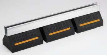
48 . A- Dura-Blok Dura-Blok Rooftop Supports SUPPORT BASES ONLY Base only - see chart for height, width and length. 00% recycled rubber, UV resistant. Load Rating - Ultimate Uniform Load (See Chart Below)* Dura-Blok channel support is designed as an economical support for piping systems, cable tray, HVAC equipment and many other applications. The Dura-Blok is UV resistant and suitable for any type of roofing material or other flat surfaces. Material effectively accepts screw fasteners for securing accessories. DBM Height x Width x Length Wt./Each Load Rating Part No. In. (mm) Lbs. (kg) Lbs. (kn) DBM 4 x 6 x 4.8 (0.6 x 5.4 x.9).5 (.0) 00 (0.89) DBP 4 x 6 x 9.6 (0.6 x 5.4 x 4.8) 4.48 (.0) 500 (.) DB SERIES SUPPORT BASE WITH B44 CHANNEL Base with 4 ga. (.9mm) galvanized channel high (5.4mm) - see chart for height, width and length. 00% recycled rubber, UV resistant. Load Rating - Ultimate Uniform Load (See Chart Below)* Dura-Blok DB-Series channel support is designed for superior support of piping systems, cable tray, HVAC equipment, walkway systems and many other applications. The Dura-Blok is UV resistant and suitable for installation on any type of roofing material or other flat surfaces. (For pipe straps/clamps, rollers and roller supports that can be used with these Dura-Blok supports, see page 44) For sloped roofs use B64 adjustable hinge fittings (see Strut Systems catalog). Height x Width x Length Wt./Each Load Rating Part No. In. (mm) Lbs. (kg) Lbs. (kn) DB0 DBP DB0 DB5 5 x 6 x 4.8 (.0 x 5.4 x.9).5 (5) 00 (0.89) DB0 5 x 6 x 9.6 (.0 x 5.4 x 4.8) 5.8 (.9) 500 (.) DB0 5 x 6 x 0. (.0 x 5.4 x 5.) 0.6 (4.8) 000 (4.45) DB0 5 x 6 x 0.8 (.0 x 5.4 x 8.) 5.99 (.5) 500 (6.6) DB40 5 x 6 x 4.4 (.0 x 5.4 x 05.5).4 (9.68) 000 (8.89) DB48 5 x 6 x 5.0 (.0 x 5.4 x 0.8) 6.0 (.40) 500 (.) DB6 SERIES SUPPORT BASE WITH B CHANNEL Base with ga. (.6mm) galvanized channel /6 high (6.9mm) - see chart for height, width and length. 00% recycled rubber, UV resistant. Load Rating - Ultimate Uniform Load (See Chart Below)* Dura-Blok DB-Series channel support is designed for superior support of piping systems, cable tray, HVAC equipment, walkway systems and many other applications. The Dura-Blok is UV resistant and suitable for installation on any type of roofing material or other flat surfaces. (For pipe straps/clamps, rollers and roller supports that can be used with these Dura-Blok supports, see page 44) For sloped roofs use B64 adjustable hinge fittings (see Strut Systems catalog). DB60 DB0 Dura-Blok Supports Height x Width x Length Wt./Each Load Rating Part No. In. (mm) Lbs. (kg) Lbs. (kn) DB60 6 /6 x 6 x 9.6 (6.5 x 5.4 x 4.8) 6.6 (.88) 500 (.) DB60 6 /6 x 6 x 0. (6.5 x 5.4 x 5.).90 (5.85) 000 (4.45) DB60 6 /6 x 6 x 0.8 (6.5 x 5.4 x 8.) 9.45 (8.8) 500 (6.6) DB640 6 /6 x 6 x 4.4 (6.5 x 5.4 x 05.5) 6.00 (.9) 000 (8.89) DB648 6 /6 x 6 x 5.0 (6.5 x 5.4 x 0.8).55 (4.6) 500 (.) DB60 * General Note: Consult roofing manufacturer or engineer for roof load capacity. The weakest point may be the insulation board beneath the rubber membrane. Reference page 8 for general fitting and standard finish specifications. 9 Page.45 DB60


 DB0-6 DB0-50 DB0-8 5 5 /8 x 6 x 8 (4.9 x 5.4 x.).6 (5.9) DB0-6 5 5 /8 x 6 x 6 (4.9 x 5.4 x 94.4) 4.6 (6.5) DB0-4 5 5 /8 x 6 x 4 (4.9 x 5.4 x 066.8) 5.5 (.04) DB0-50 5 5 /8 x 6 x 50 (4.9 x 5.4 x 0.0) 6.")
 DBM SERIES SUPPORT BASE WITH RISER ROD & CLAMP Dura-Blok Supports Base with /8-6 threaded rod and B98H clamp - see chart for height, width and length 00% recycled rubber, UV resistant.")
49 Dura-Blok Rooftop Supports DB0 SERIES SUPPORT BASES WITH B CHANNEL Two () bases bridged with ga. (.6mm) galvanized channel 5 /8 high (4.mm) - see chart for height, width and length. 00% recycled rubber, UV resistant. Load Rating: 000 lbs. (4.45kN) (Uniform Load)* Dura-Blok DB0-Series channel support is designed for superior support of piping systems, cable tray, HVAC equipment, walkway systems and many other applications. The Dura-Blok is UV resistant and suitable for installation on any type of roofing material or other flat surfaces. (For pipe straps/clamps, rollers and roller supports that can be used with these Dura-Blok supports, see page 44) Height x Width x Length Wt./Each Part No. In. (mm) Lbs. (kg) DB0-6 DB0-50 DB /8 x 6 x 8 (4.9 x 5.4 x.).6 (5.9) DB /8 x 6 x 6 (4.9 x 5.4 x 94.4) 4.6 (6.5) DB /8 x 6 x 4 (4.9 x 5.4 x 066.8) 5.5 (.04) DB /8 x 6 x 50 (4.9 x 5.4 x 0.0) 6.45 (.46) DB /8 x 6 x 60 (4.9 x 5.4 x 54.0).94 (8.4) DBM SERIES SUPPORT BASE WITH RISER ROD & CLAMP Dura-Blok Supports Base with /8-6 threaded rod and B98H clamp - see chart for height, width and length 00% recycled rubber, UV resistant. Load Rating 50 lbs. (0.kN) (Ultimate Load)* Dura-Blok DBM-Series pipe/tubing support is designed for support of single piping systems where elevation adjustment is needed. The Dura-Blok is UV resistant and suitable for installation on any type of roofing material or other flat surfaces. DBM-CT DBM- Clamp Block -Height x Width x Length Height** M-Max. Wt./Each Part No. Part No. In. (mm) In. (mm) Lbs. (kg) DBM- /CT B98HCT- / 4 x 6 x 4.8 (0.6 x 5.4 x.9) ( ).5 (.5) DBM- /4CT B98HCT- /4 4 x 6 x 4.8 (0.6 x 5.4 x.9) ( ).6 (.5) DBM-CT B98HCT- 4 x 6 x 4.8 (0.6 x 5.4 x.9) ( ).84 (.9) DBM- /4CT B98HCT- /4 4 x 6 x 4.8 (0.6 x 5.4 x.9) ( ).95 (.4) DBM- /CT B98HCT- / 4 x 6 x 4.8 (0.6 x 5.4 x.9) (6.-99.).96 (.4) DBM-CT B98HCT- 4 x 6 x 4.8 (0.6 x 5.4 x.9) ( ).0 (.) DBM- / B98H- / 4 x 6 x 4.8 (0.6 x 5.4 x.9) ( ).8 (.6) DBM- /4 B98H- /4 4 x 6 x 4.8 (0.6 x 5.4 x.9) ( ).84 (.9) DBM- B98H- 4 x 6 x 4.8 (0.6 x 5.4 x.9) ( ).86 (.0) DBM- /4 B98H- /4 4 x 6 x 4.8 (0.6 x 5.4 x.9) ( ).9 (.) DBM- / B98H- / 4 x 6 x 4.8 (0.6 x 5.4 x.9) ( ).99 (.6) DBM- B98H- 4 x 6 x 4.8 (0.6 x 5.4 x.9) ( ).0 (.4) See Pipe Hanger Catalog for dimensions and specifications. ** From bottom of rubber block to center of pipe/tubing. * General Note: Consult roofing manufacturer or engineer for roof load capacity. The weakest point may be the insulation board beneath the rubber membrane. Reference page 8 for general fitting and standard finish specifications. Page 40.46


 DBE0-8 5 /-8 x 6 x 9.6 (9")
 5. (.59) DBE0-6 5 /-6 x 6 x 9.6 (9")
50 DBE SERIES SUPPORT BASE WITH ROD RISERS & CHANNEL Base with () / electro zinc all threaded rod risers - Top channel is (5.4mm) tall. See chart for adjustable height x wide x length. 00% recycled rubber, UV resistant. Load Rating 00 lbs. (0.89kN) (To increase load capacity use load distribution plate CLDP0) Dura-Blok DBE-Series channel support is designed as a superior support of piping systems, cable tray, HVAC equipment and many other applications where elevation adjustment is critical. The Dura-Blok is UV resistant and suitable for installation on any type of roofing material or other flat surfaces. (For pipe straps/clamps, rollers and roller supports that can be used with these Dura-Blok supports, see page 44) Adjustable Height x Width x Length Wt./Each Part No. In. (mm) Lbs. (kg) DBE0-8 5 /-8 x 6 x 9.6 ( x 5.4 x 4.8) 5.68 (.58) DBE0-5 /- x 6 x 9.6 ( x 5.4 x 4.8) 5. (.59) DBE0-6 5 /-6 x 6 x 9.6 ( x 5.4 x 4.8) 5.6 (.6) Dura-Blok Rooftop Supports DBR SERIES SUPPORT BASE WITH ROD RISERS & PIPE ROLL Base with () / electro zinc all threaded rod risers and a B4- / pipe roll with sockets - base is 4 (0.6mm) high x 6 (5.4mm) wide x 9.6 (4.8mm) long. Overall height is (04.8mm) from bottom of base to contact point on roller. Pipe roll & sockets for up to / (90) pipe sizes. 00% recycled rubber, UV resistant. Load Rating 00 lbs. (0.89kN) (To increase load capacity use load distribution plate (CLDP0) Dura-Blok DBR-Series support is designed to support pipe up to / (90) nominal size where difference in elevation is required and longitudinal movement is expected. The Dura-Blok is UV resistant and approved for installation on any type of roofing material or other flat surfaces. Adjustable Height x Width x Length Wt./Each Part No. In. (mm) Lbs. (kg) DBR0- up to x 6 x 9.6 (up to 04.8 x 5.4 x 4.8) 8.0 (.) Dura-Blok Supports CLDP0 LOAD DISTRIBUTION PLATE ga. (.0mm) steel plate with slots. Dimensions: 5 /8 (4.mm) wide x 9 / (4.mm) long. Dura-Blok CLDP0 load bearing stabilizer plate increases load ratings for DBE Series and DBR Series by allowing the load from the threaded rods to be distributed over the length of the base instead of the point load where the rods attach to the base. Thickness x Width x Length Wt./Each Part No. In. (mm) Lbs. (kg) Loosen hex nuts and slide plate under the flat washers CLDP0 Ga. x 5 /8 x 9 / (.0 x 4. x 4.) 0.5 (0.4) Retighten the hex nuts with plate in place * General Note: Consult roofing manufacturer or engineer for roof load capacity. The weakest point may be the insulation board beneath the rubber membrane. Reference page 8 for general fitting and standard finish specifications. Page 4.46
 - Bases are 5 (.0mm) high x 6 (5.4mm) wide x 0. (5.mm) long. Vertical & Horizontal Riser Channels (SH Style) - 5 /8 (4.mm) x 5 /8 (4.mm) x ga. (.6mm) Fittings & Hardware - Electro-Plated Steel 00% recycled rubber, UV resistant.")
 (Uniform Load)* Dura-Blok DB DS-Series channel support with risers is designed for superior support of piping systems, cable tray, HVAC equipment, walkway systems and many other applications.")
 B + 4.")
51 Dura-Blok Rooftop Supports DB DS SERIES SUPPORT BASES WITH BSH VERTICAL & HORIZONTAL CHANNEL MEMBERS Product is shipped unassembled. Two () DB0 bases with 4 ga. (.9mm) galvanized channel high (5.4mm) - Bases are 5 (.0mm) high x 6 (5.4mm) wide x 0. (5.mm) long. Vertical & Horizontal Riser Channels (SH Style) - 5 /8 (4.mm) x 5 /8 (4.mm) x ga. (.6mm) Fittings & Hardware - Electro-Plated Steel 00% recycled rubber, UV resistant. Ultimate Load Rating: 000 lbs. (4.45kN) (Uniform Load)* Dura-Blok DB DS-Series channel support with risers is designed for superior support of piping systems, cable tray, HVAC equipment, walkway systems and many other applications. The Dura-Blok is UV resistant and suitable for installation on any type of roofing material or other flat surfaces. (For pipe straps/clamps, rollers and roller supports that can be used with these Dura-Blok supports, see page 44) B (4mm) Dura-Blok Supports DB8DS A Height (overall) B DB94DS DB56DS Width (overall) Length (overall) * General Note: Consult roofing manufacturer or engineer for roof load capacity. The weakest point may be the insulation board beneath the rubber membrane. Reference page 6 8 for general fitting and standard finish specifications. Page 4.4