ASCE Structural Evaluation Report
|
|
|
- Benedict Wilkinson
- 5 years ago
- Views:
Transcription
1 ASCE Structural Evaluation Report For 2 Dinkelspiel Station Lane Atherton, California February 11, 2009 Prepared for: Prepared by: Town of Atherton Crosby Group Office of the City Clerk 726 Main St. 91 Ashfield Road Redwood City, CA Atherton, CA 94027
2 Contents Summary of Findings...3 A Purpose and Scope...4 A.1 Purpose of Report...4 A.2 Method and Scope of Evaluation..4 A.3 Limitations...5 B Site Seismicity and Soils...7 B.1 General...7 B.2 Site Accelerations...8 B.3 Site Soils...8 C Building Descriptions...9 C.1 General...9 C.2 Original Building (1929)...9 C.3 Addition Building (1981)...9 D Tier 1 Evaluation- Findings...10 D.1 General...10 D.2 Original Building (1929)...10 D.3 Addition Building (1981)...11 E Tier 2 Evaluation-Findings...11 E.1 General...11 E.2 Original Building (1929)...12 E.3 Addition Building (1981)...13 Appendix A: Site Photos Appendix B: Evaluation Procedures Appendix C: Evaluation Checklists Appendix D: Structural Calculations Appendix E: Site Mapped Spectral Accelerations Appendix F: Cost Estimates 2 2/26/09
3 SUMMARY OF FINDINGS The following report summarizes the results of an ASCE evaluation for the facility located at 2 Dinkelspiel Station Ln. This report has been prepared at the request of the Town of Atherton to determine whether or not the facility s two buildings meet the Life- Safety Performance Level. The following is a list of findings contained within this report and any subsequent recommended mitigations. 1. Both the original 1929 building and the 1981 addition will need several modifications to meet the Life-Safety Performance Level outlined in ASCE Please note that ASCE 31 has replaced FEMA 178 and FEMA 310 as the current recognized standard for the seismic evaluation of existing buildings. 2. The original building constructed in 1929, having little to no available structural drawings, is assumed to have a single sheathed plank shear wall system. This system will need to be reinforced to accommodate the large seismic forces and create an adequate load path to transfer forces to the foundation. Additionally, it should any stucco walls be used as lateral shear walls, they must be replaced with plank or plywood sheathing walls as stucco walls are not an acceptable form of lateral-force resisting system per the current governing building codes. 3. The original structure has insufficient connections. Continuous chord elements should be installed to complete a load path along the entire perimeter of the diaphragm. Also, wood sill connections will need adequate anchorage conditions, with spacing no more than 6 feet on center. 4. For both buildings (1929 and 1981 addition) the Spanish ceramic roof tiles will need to be anchored to the roof overhang to avoid dislodging during future seismic events, a common Life Safety concern. 5. The canopy at the East entrance of the 1929 structure will need adequate anchorage back to the structural framing, with no more than 6 feet between anchors. 6. The multi-level panels at the 1929 building will need to have connections back to the structure which allow for a.02 drift ratio. Additionally, each wall panel will need a minimum of two bearing connections. 7. The hard ceiling of suspended lath and plaster in the 1929 building will additionally need to be seismically braced at every 12 square feet of area. 8. The 1981 Addition has a weak shear wall along its north wall, adjacent to where the two buildings meet. This 15 foot of wall needs to be strengthened per the Tier 2 analysis by adding plywood sheathing, appropriate blocking and proper nailing, to resist 980 pounds per linear foot of shear (ASD). If this wall cannot be strengthened, additional shear walls in the East/West direction will need to be provided to resist the remaining lateral forces. 3 2/26/09


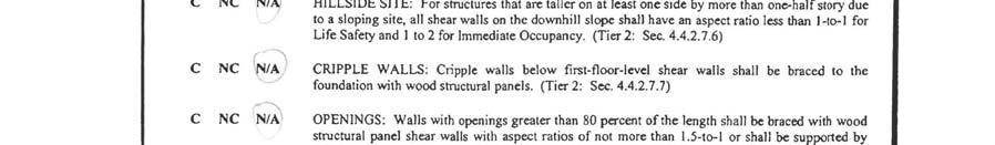
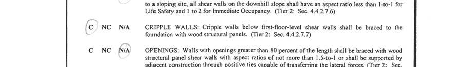
4 9. The anchorage for the wall mentioned in item #8 will also need to be strengthened or added because the existing 5/8 x 10 anchor bolts at 4-0 on center do not provide sufficient shear resistance from the wall down to the foundations. 10. For the 1981 building s exterior wall-to-diaphragm connections, further in-plane anchorage will need to be added to transfer the shear forces from the diaphragm into the rim boards, into the plywood sheathed shear walls. Also, rim board straps are recommended for in-plane shear anchorage. 11. The re-entrant corner at the North/East of the 1981 structure may potentially see torsional effects as the seismic shear is transferred in the diaphragm. This can be avoided by adding reinforcement with drag struts, which will drag the shear force in the walls back into the diaphragm and vice versa. FIGURE Building Addition Plan Summary of Recommendations 4 2/26/09
5 A. PURPOSE AND SCOPE A1. PURPOSE OF REPORT The purpose of this evaluation is to determine whether the buildings structural systems meet the Life-Safety seismic performance level required by the State of California s Real Estate Services Division (RESD). This requirement States that, The Building has been evaluated and meets the Life Safety Performance Level as set forth in FEMA 178 or its equivalent.. Since its initial publication in 1992, FEMA 178, NEHRP Handbook for the Seismic Evaluation of Existing Buildings (BSSC 1992a), has been superseded by ASCE As such, this guideline has been used for the evaluation of the said buildings. It should be noted that the facility in question is actually composed of two unique structures. These include one structure competed in approximately 1929, and one newer addition completed in The newer structure was added on to the original building, without use of any visible expansion joint. A2. METHOD AND SCOPE OF EVALUATION As noted above, the appropriate standard to assess whether or not the building meets a level of Life Safety in regards to future seismic events is ASCE This document identifies buildings of certain age and construction type as Benchmark Building or buildings that are generally perceived as compliant. Where a particular building falls within the parameters of this classification, only limited evaluation is normally required. Where a building falls outside of these parameters, a full assessment is required to determine whether the said building does or does not meet the stated performance level. For the purposes of this evaluation, this Performance Level is Life-Safety. Since the buildings in question do fall outside of these parameters, a full ASCE 31 has been performed. This evaluation starts with a Tier 1 Screening Phase that attempts to assess main components of the buildings seismic force resisting system by the use of standard checklists and simplified structural calculations. These procedures also include assessment of the buildings major non-structural components that could pose a risk to Life-Safety during a significant seismic event, and assessment of the building foundation system and site. Where any potential deficiencies are found during the initial Tier 1 analysis, ASCE-31 methodology requires that these potential deficiencies be corrected or that a refined evaluation be completed which could better assess the potential risk of these items. This second order evaluation phases are termed Tier 2 and Tier 3 and generally require substantially greater levels of effort. These subsequent assessments can either consist of a complete evaluation, or in some instances, may consist of a limited tier 2 evaluation focused on a certain perceived deficiency. This procedure is outlined in Figure 2 on page 6. For the purposes of this assessment, a complete Tier 1 and deficiency only Tier 2 evaluation was required to completely assess these buildings and included the following items: 5 2/26/09
6 1. Site visit to establish general conditions of building and to verify generally information shown on the drawings. 2. Preparation of rapid screening evaluation techniques and calculations for the structural system using ASCE design guidelines for Life-Safety Performance Level Tier Additional limited analysis using ASCE design guidelines for Life-Safety Performance Level Tier 2. A3. LIMITATIONS The services performed for this project have been provided at a level that is consistent with the general level of skill and care ordinarily provided by engineers practicing Structural Engineering. Work provided is done under the constraints of time and budget. Conclusions and information presented in this report are dependent on information provided by others. No warranty is expressed or implied. It should also be noted that a number of factors make it difficult to fully and easily assess the current condition of the existing structural elements. These include both the limited documentation available and the presence of hard finishes in many areas. Where possible, the existing acoustical ceiling tiles were temporarily removed so that these areas could be evaluated. 6 2/26/09
7 FIGURE 2- ASCE Evaluation Procedure 7 2/26/09

8 Structural Evaluation Report B. SITE SEISMICITY AND SOILS B1. GENERAL The successful performance of building in areas of high seismicity depends up the combination of strength, structural component ductility, and the presence of a fully interconnected, balanced, and complete lateral force resisting system. As the level of seismicity is decreased, the demands on the structural system are decreased. The peninsula is in a region of historically high seismic activity and seismic potential. The San Andreas fault line is located approximately 5 miles away from the structure, proving the site to be highly susceptible to an earthquake of sizeable magnitude. See Figure 3 below for a map of this. San Andreas Fault Line FIGURE 3- Site Map of Distance to Nearest Fault Line 8 2/26/09
9 B2. SITE ACCELERATIONS In general site Seismicity or the potential for strong ground motion is classified into regions of Low, Medium, and High. These regions are based upon mapped site accelerations SS and S1 which are then modified by site coefficients Fa and Fv to produce Design Spectral Accelerations SDS (short period) and SD1 (1 second). Design Spectral accelerations computed for this site are as follows: SDS= 1.159g SD1=.759g As indicated below by the site accelerations, this standard places the subject property in a region of HIGH Seismicity. Region of Seismicity SDS SD1 Low <.167g <.067g Moderate <.500g >.167g <.200g >.067g High >.500g >.200g FIGURE 4- Site Seismicity Based on Design Accelerations B3. SITE SOILS The foundations are made up of continuous grade beams along the perimeter of the building, which are visible from the exterior of the structure, along with spread footing over the interior of the building. No soils report is available, but the following site soils assumptions were made based on the building site location. Site Characteristics Fault Rupture Potential Liquefaction Potential Land Slide Potential Assumed Moderate Moderate Site is Flat -Assumed Low FIGURE 5- Site Characteristics 9 2/26/09
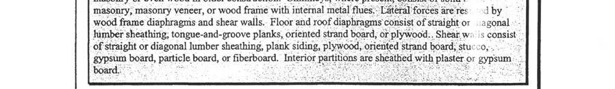
10 C. BUILDING DESCRIPTIONS C1. GENERAL The subject properties for this evaluation consist of two structures, one built in 1929 and the other built in Each structure is approximately rectangular in plan area and was constructed from light framed wood panels or sheathing. Limited structural drawings were available, but a set of drawings from the 1981 addition was available for some of the evaluation. Each building has been evaluated independently and their respective evaluations are presented in Appendices C-E. Descriptions of each building as well as FEMA building designations are given below. C2. ORIGINAL BUILDINGS (1929) The original building is two stories tall and is approximately 1600 square feet. The building appears to have been constructed in 1929 and is comprised of light framed timber. Due to a lack of available structural drawings and hard ceilings, it is assumed that the structure is made up of straight sheathed wood planks, studs and joists, with no structural plywood as plywood wasn t an available construction material in Building Code Exterior Wall System/Cladding ASCE 31 Building Type Lateral Force System Roof System Second Floor System Interior Columns First Floor system Foundation System Building Characteristics- Structural Original 1929 Construction 1927 UBC (assumed) Planks (assumed) Type W1- Wood Light Frame Planks (assumed) Planks over wood joists Planks (assumed) n/a Planks (assumed) Continuous footings Figure 6- Structural Characteristics for Original 1929 Building C3. LIBRARY ADDITION (1981) In 1981, one building was added adjoining the east end of the original 1929 structure. The one story building is approximately 63 x46 and is approximately 3100 square feet. The building appears to have been constructed in 1981 and is comprised of plywood sheathed walls around the with four columns at the interior at an approximate grid spacing of 12 on center each way. The building has a plywood sheathed roof system with 15 x 5 glu-lam beams and 15 x 1 ½ ceiling joists. 10 2/26/09
11 Building Characteristics- Structural 1981 Addition Building Code 1979 UBC (assumed) Exterior Wall Plywood Sheathing System/Cladding ASCE 31 Building Type Type W1 Wood Light Frame Lateral Force System ½ Plywood Sheathed Wood Studs (assumed) Roof System Panelized plywood roof system with wood joists and girders and glu-lam beams/collectors Interior Columns TS 4x4x1/4 First Floor system Panelized plywood with wood joists and girders and glu-lam beams Foundation System Continuous/spread footings Figure 7- Structural Characteristics for 1981 Addition D. TIER 1 EVALUATION PHASE- FINDINGS D1. GENERAL The original building and the one story addition have been evaluated independently. The original building is attached to the 1981 addition by an adjoining wall. The new building is directly attached to the original building with no visible seismic joint. The newer 1981 addition was found to have minor deficiencies which will require some additional work to reach the Life-Safety performance level as stated in ASCE However, the original 1929 structure was found to have potentially major structural deficiencies, which will need further investigation and renovations to bring up to an appropriate Life-Safety performance level. These items are noted below. D2. ORIGINAL 1929 BUILDING There are a few major deficiencies which should be corrected to bring the building up to an adequate Life-Safety Performance Level per ASCE These items include an insufficient lateral-force-resisting system, weak connection details and unanchored cladding and canopy. These are expanded as follows: 1. The original building is assumed to rely only on single plank sheathed walls as the primary lateral-force-resisting system, which has a very low shear capacity to resist lateral forces. Given this information as well as a lack of structural drawings to see the specific design of the lateral system, it is assumed that an insufficient load path exists for seismic effects to transfer the inertial forces to the foundation. 2. The original structure has deficient connections as well. It is safe to assume that the interconnection between the first and second floor isn t capable of transferring overturning and shear forces, especially on account of the insufficient lateral-forceresisting system. Also, wood sills are assumed to require additional proper anchorage to the foundation. 11 2/26/09
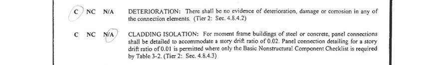
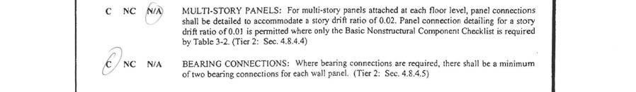
12 3. During the site visit it was noticed that the Spanish tiles laid along the roof overhangs are not anchored to the structure, creating a potential hazard to life safety in the event of an earthquake, where the heavy tiles will be free to fall. Multi-story panels will need revised detailing to accommodate the story drift. Walls will also require a minimum of two bearing connections for each wall panel. Finally, the canopy system at the main entrance of the original structure lacks adequate anchorage back to the structural framing. D3. ADDITION (1981) Constructed in 1981, the one story addition appears to be in relatively good shape, though it has several apparent deficiencies. These are explained as the following: 1. There is an inadequacy in the lateral force resisting system in the east/west direction. From the Tier 1 calculations in Appendix D, average shear demand in this direction is 375 pounds per linear foot, however the wall adjoining the original 1929 building to the 1981 addition is assumed to have wood plank sheathing, which only allows a max of 100 pounds per linear foot of shear. As this is the east/west shear wall on the north face of the 1981 addition, the weakness represents a potential Life Safety concern. 2. The Spanish tiles along the roof overhangs are not properly anchored to the structure, which poses a threat as a seismic event could easily knock one of the tiles loose and down to the walkway below. Currently, the tiles sit one on top of the other, free to be shift under lateral force. 3. Finally, the lay-in tiles that occur at the ceiling of the library in the 1981 addition are not secured with clips, though they are laterally restrained by the grid system that they lay in, posing very little threat to falling down. E. LIMITED TIER-2 EVALUATION- SUPPLMENTAL FINDINGS E1. GENERAL Where items are initially noted as NC or Non-Compliant during the Tier 1 evaluation, the screening process may end and a rehabilitation procedure implemented. As an alternative, the designer may choose to conduct a more detailed evaluation which may eventually reveal that the condition in question, while existing, does not represent a Life-Safety condition. This subsequent step is called a Tier 2 evaluation and is shown diagrammatically in Figure 2. As indicated below, several conditions were determined to be non-compliant during the initial screening. Some of these items, however, were not Life-Safety concerns. See below for further evaluation. 12 2/26/09
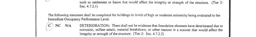
13 E2. ORIGINAL 1929 BUILDING From this building s initial Tier 1 analysis, several non-compliant items were re-evaluated per the Tier 2 process, where enough information was available to assess. The noncompliant load path required no Tier 2 analysis. Due to the dated construction of this building, it is safe to assume that the chord elements are discontinuous. This discontinuity can make the diaphragm more flexible, thereby causing more damage around the perimeter. To provide continuity, continuous chord elements should be installed to complete a load path, which is necessary in achieving a Life-Safety performance level. Also, it is safe to assume that wood sill bolts are insufficient as well. Adequate bolts should be placed no more than 6 feet apart, capable of resisting lateral forces from the lateral system above. As previously stated, the shear walls of the structure are assumed to be single plank sheathed walls, which have relatively small shear capacities. Therefore, as one of the main deficiencies in this building, causing a life-safety hazard, more sufficient shear walls will need to be added to strengthen the lateral system s resistance to earthquakes. As there is no evidence otherwise, it cannot be denied that stucco might be used as shear walls in some locations of the original 1929 structure, which is in direct violation of current code regulations. Therefore an alternate, lateral system must be used in place of any stucco walls. Because there was no existing anchorage for the Spanish ceramic tiles above the roof overhangs, no calculations were necessary to check adequacy. Anchorage must be provided for these items so as to avoid life-safety hazards of falling tiles off of the overhangs in the event of an earthquake. Multi-story panel detailing will need to accommodate a drift ratio of If the connectors are expected to deform, they should be capable of doing so without loss of structural support for the panel. Panel bearing connections will also need to be upgraded, so as to provide a minimum of two bearing connections per panel. Only one bearing connection can result in a dangerous lack of redundancy. If connections are non-existent, they will need to be installed to this minimum design. The canopy located over the East entrance over the original 1929 structure will need to be properly anchored to the structural framing at no more than 6 feet on center. Improper anchorage can present a life-safety hazard. Should existing anchorage be found, it should be checked for required spacing as well as strength especially for shallow anchors which commonly fail in pull-out. Finally, the last non-compliant item being analyzed in the Tier 2 assessment for the 1929 structure is the suspended lath and plaster. The hard ceilings in this building will need seismic bracing for every 12 square feet of area, as this element may be acting as a structural diaphragm to resist in-plane seismic forces. 13 2/26/09
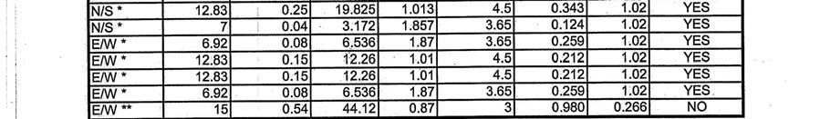
14 E3. ADDITION (1981) From the findings in the Tier 1 evaluation, the lateral-force-resisting system in the east/west direction was in question. The Tier 2 requirements call for a more exact approach to the lateral force calculations, showing a more precise distribution of lateral forces to each shear wall. From the calculations shown in Appendix D, the single sheathed wall in question only has an expected strength of just 266 pounds per linear foot, where as the demand is 980 pounds per linear foot. Upon this more precise analysis approach, it is apparent that the shear wall is highly under designed and the lateral system along this line of wall will need to be reinforced to resist higher loads. Because there was no existing anchorage for the Spanish ceramic tiles above the roof overhangs, no calculations were necessary to check adequacy. Anchorage must be provided for these items so as to avoid life-safety hazards of tiles falling off of the overhangs in the event of an earthquake. Per the Tier 2 procedure, the ceiling lay-in tiles are best evaluated based upon engineering judgment. Because the tiles are laterally secured between grids and they are constructed of light weight material, it is our opinion that the tiles need no additional clips for anchorage. In the general analysis of the Tier 2 procedure, several items were deficient as well. Inplane anchorage from the diaphragm to the shear walls was found to be insufficient. Additional connections should be provided, including rim board straps to resist in-plane forces. Also, at the foundation level, extra anchor bolts should be installed along the wall that joins the 1981 building to the original 1929 structure. Finally, the re-entrant corner of the 1981 structure should be reinforced with drag struts to resist any torsional effects in the diaphragm. 14 2/26/09
15 APPENDIX A Site Photos 15 2/26/09
16 Original 1929 Two Story Structure Connection where 1929 Two Story Structure Meets 1981 Addition 16 2/26/09
17 Continuous Footing Along Exterior of 1981 Addition Floor Joists Below 1981 Addition 17 2/26/09
18 Floor Joists Below 1929 Structure Canopy Adjacent to 1929 Structure 18 2/26/09
19 APPENDIX B Evaluation Procedure 19 2/26/09
20 20 2/26/09
21 APPENDIX C Evaluation Checklists 21 2/26/09


22 22 2/26/09

23 23 2/26/09


24 24 2/26/09

25 25 2/26/09

26 26 2/26/09


27 27 2/26/09


28 28 2/26/09
29 29 2/26/09


30 30 2/26/09
31 31 2/26/09

32 32 2/26/09

33 33 2/26/09


34 34 2/26/09

35 35 2/26/09

36 36 2/26/09

37 37 2/26/09


38 38 2/26/09

39 39 2/26/09


40 40 2/26/09
41 41 2/26/09
42 APPENDIX D Structural Calculations 42 2/26/09
43 43 2/26/09
44 44 2/26/09
45 45 2/26/09
46 46 2/26/09
47 47 2/26/09
48 48 2/26/09
49 49 2/26/09
50 50 2/26/09
51 51 2/26/09

52 52 2/26/09
53 53 2/26/09
54 54 2/26/09
55 55 2/26/09
56 56 2/26/09
57 57 2/26/09
58 58 2/26/09
59 59 2/26/09
60 60 2/26/09
61 61 2/26/09
62 62 2/26/09
63 APPENDIX E Site Mapped Spectral Accelerations 63 2/26/09
64 Conterminous 48 States 2003 NEHRP Seismic Design Provisions Latitude = Longitude = Spectral Response Accelerations Ss and S1 Ss and S1 = Mapped Spectral Acceleration Values Site Class B - Fa = 1.0,Fv = 1.0 Data are based on a 0.01 deg grid spacing Period Sa (sec) (g) (Ss, Site Class B) (S1, Site Class B) Conterminous 48 States 2003 NEHRP Seismic Design Provisions Latitude = Longitude = Spectral Response Accelerations SMs and SM1 SMs = Fa x Ss and SM1 = Fv x S1 Site Class D - Fa = 1.0,Fv = 1.5 Period Sa (sec) (g) (SMs, Site Class D) (SM1, Site Class D) Conterminous 48 States 2003 NEHRP Seismic Design Provisions Latitude = Longitude = Design Spectral Response Accelerations SDs and SD1 SDs = 2/3 x SMs and SD1 = 2/3 x SM1 Site Class D - Fa = 1.0,Fv = 1.5 Period Sa (sec) (g) (SDs, Site Class D) (SD1, Site Class D) Figure E1- Mapped Spectral Accelerations (Site Adjusted) 64 2/26/09
65 APPENDIX F Cost Estimates 65 2/26/09
66 The Crosby Group Projec Date: 2/09 Sht: Description: Seismic Upgrade By: DPN Ck: DPN Cost Estimate Item Description Quantity Units Unit price Total price Remarks 1 New Shear Walls 110 LF $ $11, Chord & Collector Upgrade 360 LF $30.00 $10, Wood Sill Connections 360 LF $20.00 $7, Diaphragm upgrade incl part. Reroof SQFT $28.00 $114, Roof Tile Anchorage 1440 SQFT $10.00 $14, Entrance Canopy Anchorage 1 EA $6, $6, Foundation work 360 LF $60.00 $21, Hard Ceiling Anchorage 1800 SQFT $12.00 $21, Sub Total: $207,400 9 Overhead & General 15% $31, Condition Sub Total: $238, Profit 10% $23, Sub Total: $262, Engineering $24, Contingency 10% $20, Total Estimate: $307,101