PARK COUNTY PLANNING DEPARTMENT 1002 SHERIDAN AVE. CODY, WY OR
|
|
|
- Sabina Booth
- 5 years ago
- Views:
Transcription

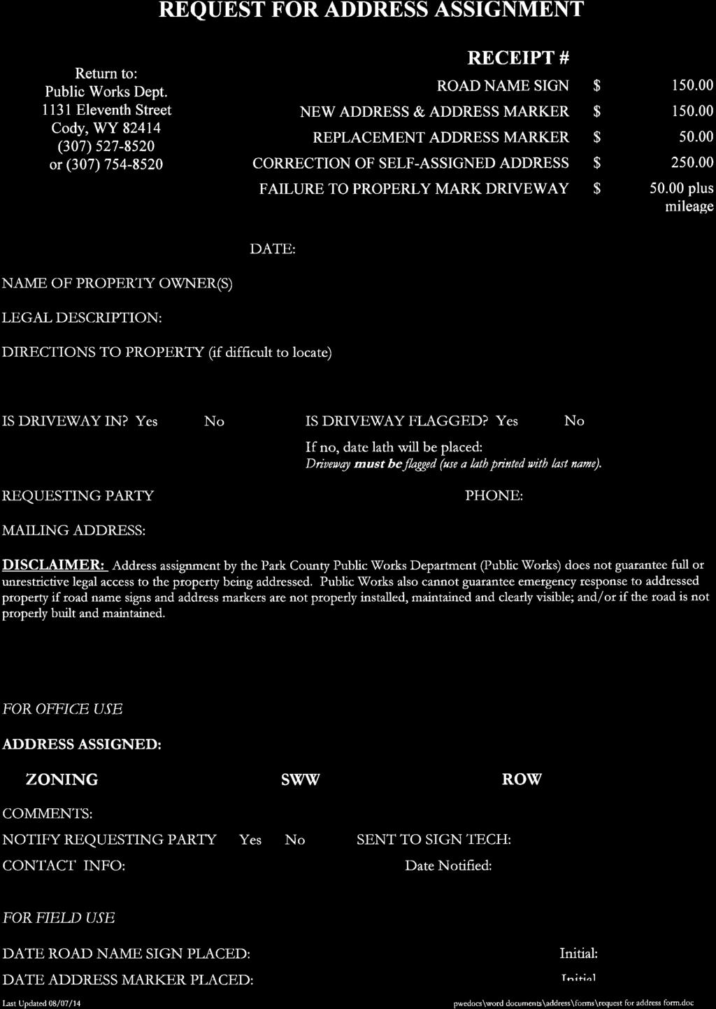
1 PARK COUNTY PLANNING DEPARTMENT 1002 SHERIDAN AVE. CODY, WY OR PARK COUNTY PUBLIC WORKS th ST CODY, WY OR ANYONE CONSTRUCTING, PLACING OR MODIFYING A STRUCTURE WITHIN THE UNINCORPORATED AREAS OF PARK COUNTY, WYOMING OR WORKING WITHIN A COUNTY RIGHT-OF-WAY MUST OBTAIN THE FOLLOWING PERMITS: SEPTIC SYSTEM PERMIT: Issuing Authority: PARK COUNTY PLANNING & ZONING OFFICE Fee: $ for a new septic system; $75.00 for repairs/replacement Description: Approved permit required prior to construction or modification of any septic system within Park County. Must be inspected prior to covering the system. ZONING/BUILDING PERMIT: Issuing authority: PARK COUNTY PLANNING & ZONING OFFICE Fee: $25.00 Description: Approved permit required prior to construction, placement or modification of any structure within Park County. (Additional permits/approvals may be required depending on your project.) RIGHT-OF-WAY PERMIT: Issuing authority: PARK COUNTY PUBLIC WORKS DEPARTMENT Fee: None Description: Approved permit required prior to working within any county right-of-way including, but not limited to, driveways, culverts, mailboxes, fences, utility lines, general construction; application to include a Traffic Control Plan. Depending on situation and complexity of work, applicants may be required to provide construction plans for approval. REQUEST FOR ADDRESS PERMIT: Issuing authority: PARK COUNTY PUBLIC WORKS DEPARTMENT Fee: See list of Related Fees Description: New address marker or replacement marker; new road name and road sign. NOTE: New road name requirements may apply, including adherence to Park County Road Name Standards and Procedure. ROAD NAME SIGN $ NEW ADDRESS & ADDRESS MARKER $ REPLACEMENT ADDRESS MARKER $50.00 CORRECTION OF SELF-ASSIGNED ADDRESS $ FAILURE TO PROPERLY MARK DRIVEWAY $50.00 PLUS MILEAGE Expect a minimum of seven (7) working days for permit processing time A minimum 24 hour advanced notice must be given to the Planning Department for Septic inspections THE STATE FIRE MARSHALL S OFFICE REQUIRES YOU CONTACT THEM AT FOR AN ELECTRICAL INSPECTION Revised July 2014

2 FEE $25.00 RECEIPT# PERMIT # PARK COUNTY BUILDING PERMIT APPLICATION Planning & Zoning Department 1002 Sheridan Ave., Ste 109 Cody, WY A building permit must be approved by the Planning Office before This requirement applies to all unincorporated areas. any construction is started and is required to: Locate, erect or construct any building or structures; Enlarge the outside dimensions of any building or structure; Reconstruct any building or structure within the designated floodplain (other permits required). If construction authorized by a zoning permit has not been started within 1 (one) year, this permit shall be null and void. Construction must be completed within 3 (three) years. Please allow up to 14 days for application to be processed. Owner Information Contractor Name: Mailing Address: City, State, Zip: Phone: OR Construction Describe the structure and intended use: Sq.Ft. Information Does the construction increase an existing Ο Yes Ο No building occupancy rating (such as net increase in number of bedrooms for existing home)? Small Wastewater Permit Ο None required Ο Expansion / repair required Ο New required Ο Existing adequate Permit #: Date: DLO: Property Information Property Identification # (14 digit Tax ID): Property Address if other than mailing address: Subdivision Name: Lot #: _ PLEASE NOTE: Complete site plan drawing on the back of this form. Lighting Standards shall apply (Appendix 21). Structure must be 20 feet from road right-of-way. IMPORTANT! Contact the _ Irrigation District before you begin construction to check for easement and/or irrigation facility locations. Revised 3/2017 PAU

3 SITE PLAN: Draw a general site plan showing the proposed structure and these features: Distances from rivers and major creeks on or near the property; Distances from property lines; Distances from any nearby roads; Location of other existing buildings on the property; Approximate location of water and wastewater systems; Irrigation facilities; North arrow. The information presented in this application is true and correct to the best of my knowledge. OWNER/APPLICANT Signature: Date Office Use Date Received: General Location Use Classification: Planning Area: Zoning District: Overlay District: Ο NA Ο Ag Ο Airport Ο Flood Map #: Flood Permit # Please Note: PERMIT APPROVED Date Revised 3/2017 PAU

 Well Cistern Municipal Printed")
4 Name: Permit # FOR OFFICE USE ONLY PERMIT TO CONSTRUCT Date Received: Receipt # Staff: Designated Local Official: Date Approved: Inspection Date: Inspector Approval: Comments: ZONING / BUILDING PERMIT Printed Name: Mailing Address: Physical Address: City, State: Zip: Phone Number: Property Tax ID Number: None Required New Required Existing Adequate Permit # Planner: Date Verified: Park County Small Wastewater Treatment Facility Application Park County Planning Department 1002 Sheridan Avenue, Ste. 109 Cody, WY or PROPERTY OWNER New System: Repair / Replacement: Reason for Repair / Replacement: Water Source: (Check one) Well Cistern Municipal Printed Name: Mailing Address: City, State: Zip: Phone Number: Printed Name: Phone Number: PROPERTY OWNER Signature Required: INSTALLER INFORMATION ENGINEER INFORMATION (if Necessary) Signature: Mailing Address: City, State: Zip:

5 SITE SUITABILITY The owner must be aware of the depth of any impermeable soil layers, high groundwater levels, and slope when considering the septic system location. The questions below will ensure you have gathered the information necessary to determine if a conventional septic system is appropriate. REQUIRED: An exploration pit within the proposed leach field area, 7-8 feet in depth, at least 4 feet below the proposed leach field Color photo of the excavation pit with tape measure against the side of the pit. Make sure you have adequate lighting to show depth of the hole. Color photo of proposed leach field area. Write property owners name on the photo or make sure it is clearly identified. Submit photos with application or to pumphlett@parkcounty.us Excavation Does the soil exploration pit lie within the area of the proposed leach field? Was the bottom of the required soil exploration pit at least 4 ft below the bottom of the proposed leachfield, usually minimum of 7-8 feet total depth? This is required. Take a color photograph of the excavation, showing a tape measure against the sidewall of the trench. Submit a color copy of the photograph as a separate sheet. Photo included in packet? Depth of the excavation? Who conducted the excavation? Soil Surface: Mottled appearance with areas around roots or cracks that looks like rust Soil stained dark red-black or red-brown Alkali crust, rotten egg smell, blue-grey or greenish-grey color Depth of these features: Rock Layer Clay Layer Groundwater Date: Yes No Yes No Yes No Yes No Yes No Yes No SAMPLE SOIL HORIZON: DRAW SOIL HORIZON
6 Slope What is the estimated slope of the proposed leachfield area? Take a color photograph of the proposed leach field area and attach a copy as a separate sheet. How far away is the nearest break in slope (the side of the hill or where the slope becomes abruptly steeper) from the proposed leach field area? Other How far away is the nearest surface water body, such as a lake, river, pond, creek, ditch, or wetland from the proposed leachfield area? How far away are areas where the soil may be compacted by vehicles, such as roads or parking spaces, from the proposed leach field area? How far away are water supply wells (drinking or irrigation wells), cisterns, or water supply lines from the proposed leach field area? Do surface drainage features (ditches, depressions, or swales) direct runoff from paved areas such as roofs, patios, or driveways, away from the leach field? SITE PLAN REQUIREMENTS Attach a sketch of your site plan as a separate sheet, showing each of the items in the table below, if applicable. Required Required Check Box Setback Setback If Shown Element Distance to Distance to On Site Plan Septic Tank Leach Field Yes No Is the Setback Distance Satisfied? (feet) (feet) Property lines Yes No All buildings, roads, and driveways Yes No Setback to buildings w/out a foundation drain 5 10 Yes No Setback to buildings with foundation drain 5 25 Yes No Private wells (including neighbors) Yes No Public water supply wells Yes No Potable water supply lines Yes No Surface water (ditch, pond, intermittents waterways, etc.) Yes No Septic tank 10 Yes No Break in slope (where slope gets abruptly steeper) Yes No Cisterns Yes No Leach field & replacement leach field 10 Yes No North arrow Slope (arrow pointing downslope) Location of numbered percolation test holes (numbered) Location of soil exploration pit Location of cleanout port(s)
7 SITE PLAN DRAWING EXAMPLE SITE PLAN DRAWING Include the location of the septic tank and drain field, the layout of the drain field lines and length, leach field replacement areas, water system (irrigation ditches, streams, water lines, wells, etc.) structures, property lines and other significant features. Include distance between plotted items.
8 SEPTIC TANK AND PIPING WORKSHEET Septic Tank Manufacturer: Size (gallons): Model No./Number of Chambers: Tank Material (Check one) Concrete Fiberglass Thermoplastic Other (please describe): Is this tank of the approved list? Yes No Don't Know If no, provide a tank diagram from the manufacturer. If you cannot locate a diagram from the manufacturer, complete the following 3 rows. Internal Dimensions: Length (in): Width (in): Height (in): Please complete for tanks Liquid Depth (in): Amount of Air Space Between Top of NOT on approved list. Liquid and Chamber Ceiling (in): Depth of backfill over tank (minimum of 6" required) Operating ( * * ) 231 = gallons Capacity Length(in) Width (in) Liquid Depth Yes No Yes No Yes No Yes No Do access openings have a locking device? Yes No Piping What will the piping material What is the proposed pipe size between the house and the septic (diameter)? tank be? Will the installer lay the pipe from the house to the septic tank in a straight line? Yes No If no, will the installer include the required cleanout ports at any alignment change greater than 22.5 degrees? Yes No Will the pipe from the house to the septic tank be more than 100 feet long? Yes No If yes, will the required cleanout ports be spaced along the line every 100 feet or less? Yes No DEQ recommends a cleanout port facing each direction between the building and the tank. If only one is used, which direction does the required cleanout port face? Will the piping have a minimum slope of 1/4 inch per foot (2%)? If the installer uses more than one trench, they must use a distribution box or flow divider tee to equalize flow. Will the system include a distribution box or flow divider tee? Will the leachfield trenches be less than 100 feet long? This is required. Number of bedrooms, if a residence: If more than 4 bedrooms: Does the tank have additional capacity of 150 gallons per additional bedroom above 1,000 gallons? Tank has a 20-inch access opening in EACH compartment of the tank and a riser from the access opening that terminates at a max of six (6) inches below the ground surface? Septic Tank is installed on a level grade, with firm bedding to prevent settling, and without rock or other obstructions touching the tank as per WQRR Chapter 25, Section 10(a)(ii)? If installing two tanks in a series, install the downstream tank a minimum of 2 inches lower than the first to insure proper flow. Will the installer use a series of tanks as described? Toward Building Toward Tank Yes No Yes No Yes No
 test estimates the rate at which the water will percolate, or move, through the soil. The information provided by perc tests is necessary to design leachfields correctly.")
9 PERCOLATION TEST INSTRUCTIONS In order for a septic system to perform properly, the wastewater must move through the soil at an ideal rate, neither too fast nor too slow. A percolation (perc) test estimates the rate at which the water will percolate, or move, through the soil. The information provided by perc tests is necessary to design leachfields correctly. Follow the steps below to complete the perc test. 1. Location of Percolation Test Holes. The perc test holes must be spaced uniformly over the proposed leachfield site. A minimum of three (3) test holes are required. 2. Test Hole Preparation: Dig or bore each hole 12 inches wide as deep as the proposed depth of the leachfield (usually between 30 and 40 inches). Make sure the sides are vertical and scrape the sides and bottom of the hole with a sharp pointed instrument to restore a natural soil surface. Remove loose soil from the hole and place 2 inches of course sand, washed gravel or stone in the bottom in order to prevent scouring or sealing. 3. Presoaking: Presoaking is absolutely required to get a valid perc test result. Presoaking allows the water conditions in the test hole to reach a stable condition that is similar to a leachfield. Presoaking time varies with soil conditions, but presoak holes for at least 4 hours. Maintain at least 18 inches of water in the test holes for at least 4 hours, then allow the soil to swell for 12 hours (overnight is good) before starting the perc test. For sandy or loose soils, add 8 inches of water above the gravel or course sand. If the 18 inches of water seeps away in 18 minutes or less, add 18 inches of water a second time. If the second filling of 18 inches of water seeps away in 18 minutes or less, the soil is excessively permeable and the site is unsuitable for a conventional disposal system. If this is the case, contact your county small wastewater permitting authority or DEQ district office. 4. Perc Rate Measurements. Fill each hole with 12 inches of water and let the soil re-hydrate for 15 minutes prior to taking any measurements. Establish a fixed reference point such as a flat board placed across the top of the hole to measure the incremental water level drop at the constant time intervals. Measure the water level drop to the nearest 1/8 of an inch with a minimum time interval of 10 minutes. Normal Time intervals are usually 10 or 15 minutes Refill the test hole to 12 inches above the gravel before starting the measurements. Measure down to the water from the fixed reference point. Record this value on the first line in the perc test data sheet. Take another measurement after the time interval has elapsed and record on the second line of the table. Calculate the water level drop and record in the table. Continue the test until the water level drop rate has stabilized, i.e. three consecutive measurements within 1/8 inch of each other. Before the water level drops below 1 inch above the gravel, refill the test hole to 12 inches. Some test holes may take longer than others. If the drop rate continues to fluctuate, use the smallest drop rate out of the last six intervals for your calculations.
10 Depth of Hole 33" 34 1/4" 29 2/4" Time of Day Time (min) Measure to nearest 1/8 inch Time of Day Time (min) Measure to nearest 1/8 inch Time of Day Time (min) 1/8 inch Water Level Drop PERCOLATION TEST EXAMPLE Hole #1 Hole #2 Hole #3 Water Level Drop Measure to nearest Water Level Start 9: Start 9: Start 9: : : : : : : : : :51 N/A N/A 9:55 N/A N/A 9: Refill 9: Refill 10: : : : Refill 10: : : : End 10: : End 10: Time Interval (Minutes) Final Interval Drop (In.) Perc Rate (min/inch) Time Interval divided by Interval Drop = Percolation Rate Design Perc Rate (min/inch) Design Perc Rate (min/inch) 2.35 Drop
11 Test holes were pre-soaked for: (hours/minutes) Time Interval: min. Hole #1 Hole #2 Hole #3 Depth of Hole 33" 34 1/4" 29 2/4" Time of Day Time (min) Measure to nearest 1/8 inch Time of Day Time (min) Measure to nearest 1/8 inch Time of Day Time (min) Measure to nearest 1/8 inch Water Level Drop PERCOLATION TEST DATA SHEET Water Level Drop Water Level Drop Time Interval (Minutes Final Inverval Drop (inches) Perc Rate (min/inch) Time interval divided by Interval Drop = Precolation Rate Design Perc Rate (min/inch) Design Perc Rate (min/inch) Printed Name of Person Conducting Test: Signature: Phone Number:
12 LEACHFIELD SIZING WORKSHEET How many bedrooms does the residence have? Residential Building bedrooms Does the residence have an unfinished basement? Yes No If yes, add 2 more bedrooms to the number above. Total Bedrooms Enter the number of gallons per day (gpd) of wastewater generated that corresponds with the number of bedrooms in Box 1 below. 1 bedroom 2 bedrooms 3 bedrooms 4 bedrooms 5 bedrooms 6 bedrooms * 150 gpd 280 gpd 390 gpd 470 gpd 550 gpd 630 gpd * Add an additional 80 gallons per day for each bedroom over 6. Non-Residential Building Refer to Chaper 15, Table 2. Show calculations and attach a separate sheet if necessary Design Flow (gpd) Box 1 Enter value from cells above or Chapter 25, Table 2 attached Loading Rate (gpd/ft 2 ) Design Flow (gpd) Per Rate min/inch Loading Rate gpd/ft 2 Per Rate min/inch Loading Rate (gpd/ft 2 ) Enter Loading rate for your percolation test from above table. Leach Field Sizing (ft 2 ) Required Leach Field Area (ft2) Divide design flow (Box 1) by loading rate (Box 2). Round up to the nearest whole number. / Design Flow (Box 1) Loading Rate gpd/ft Loading Rate (Box 2) Per Rate min/inch Loading Rate gpd/ft Leach Field Area (Box 3) Example: 300 gpd / 0.62 gpd/ft 2 = or 484 ft2 Box 2 Box 3

13 LEACH FIELD DESIGN INSTRUCTIONS Arrange conventional septic system leach fields using either a trench or a bed layout. Construct either trench or bed layouts using either perforated pipe or open-bottom chamber systems. DEQ prefers trench layouts because they provide more surface area for absorption of wastewater into the soil. Trenches also treat wastewater more efficiently because the undisturbed soil between the trenches allows more oxygen to reach the microbes that break down and treat the wastewater. For this reason, trenches are also more effective when soils have lower or "slower" percolation rates. Use bed layouts where space for a leach field is limited and only where soils have higher or "faster" percolation rates. DEQ considers trenches spaced less than three (3) feet apart as bed layouts. To design your leach field, follow these steps: 1) Choose either a trench or a bed layout. 2) Choose either perforated pipe or open-bottom chambers for your leach field. 3) Fill out the layout worksheet and diagram that correspond to your selection. This worksheet will determine how many trenches you need or how large to make your bed. 4) Submit only the worksheet and diagram that you completed. Trench Leach Field System: Perforated Pipe Trench Layout Chambered Trench Layout Bed Leach Field System: Perforated Pipe Bed Layout Chambered Bed Layout Install Leach Fields to ensure equal distribution of wastewater effluent among all the trenches. Equal distribution allows the use of the entire infiltrative surface of the Leach Field and prevents overloading part of the Leach Field. Use either a piping header or distribution box (D-box) to distribute wastewater effluent equally among the trenches of a Leach Field. A piping header system conveys wastewater effluent to each disposal trench using a network of solid piping. Split the discharge line from the septic tank using a T-pipe fitting (see example below). If there is an odd number of trenches in the Leach Field, use a distribution box to divide wastewater effluent evenly among the trenches (see example below). Distribution boxes are typically made of concrete or wastewater grade plastics and are watertight with a single inlet set at a higher elevation than the outlets. Construct outlets so that their elevations are equal relative to one another. DEQ does not require installation of Leach Field trenches in a straight line. In fact, it is always preferable to follow the contour of the land. Additionally, never install the Leach Field in floodways, at the base of slopes, or in depressions where runoff water could flood the Leach Field. Construct Leach Fields in areas with good surface drainage, where the water cannot pond over the Leach Field.
14 Design Required Leach field Area Depth of Trench Below Pipe (ft) Width of Trench (ft) Absorptive Area Per Linear Foot of Trench (ft 2 /ft) Total Trench Length (ft) Trench Layout Number of Trenches to Use PERFORATED PIPE TRENCH LAYOUT WORKSHEET + + = (Box 2) (Box 2) (Box 3) Absoption Area Total Trench Length (ft) (from Box 5) less than (Box 1) (Box 4) Total Trench Length Minimum Number of Trenches to Use 1 2 3* 4 5* 6 Number of Trenches to Use = Length of Trenches = * A distribution box, or D-box, is required when an odd number of trenches is used. Box 1 Box 2 Box 3 Box 4 Box 5 Box 6
15 PERFORATED PIPE TRENCH LAYOUT DIAGRAM
16 Chamber Manufacturer Model Nominal Length (ft) Nominal Width (in) Nominal Height (in) Design Effective Length (ft) Required Leachfield Area (Page, Box 3) Equivalent Area Per Unit (See Table, Page ) Number of Chamber Trench Layout Total Trench Length (ft) Number of Trenches to Use CHAMBERED TRENCH LAYOUT WORKSHEET Box 1 Box 2 Box 3 + = Box 4 (Box 2) (Box 3) No. of Chambers (Round Up) + = Box 5 (Box 4) (Box 1) Total Trench Length Total Trench Minimum Number Box 6 Length (ft) of Trenches (from Box 5) to Use Number of Trenches to Use = less than Length of Trenches = * * A distribution box, or D-box, is * required when an odd number of trenches is used.
17 CHAMBERED TRENCH LAYOUT DIAGRAM
 (Box 3) Total Bed Area Yes No If No, Adjust Bed Width (Box 2) and Bed Length (Box 3) until Box 4 is greator than box 1 If Yes, Complete bottom of this Page Box 1")
18 PERFORATED PIPE BED LAYOUT WORKSHEET Design Required Leachfield Area Total Excavated Depth (ft) Depth below pipe (ft) Bed Layout Bed Width (ft) Bed Length (ft) Bed Total Square Feet Is Box 4 greater than or equal to Box 1 + = (Box 2) (Box 3) Total Bed Area Yes No If No, Adjust Bed Width (Box 2) and Bed Length (Box 3) until Box 4 is greator than box 1 If Yes, Complete bottom of this Page Box 1 Box 2 Box 3 Box 4
19 PERFORATED PIPE BED LAYOUT DIAGRAM
 Box 3 Number of Chamber Total Chamber Length (ft) Number of Chambers to Use + = (Box 2) (Box 3) No.")
20 CHAMBERED BED LAYOUT WORKSHEET Chamber Manufacturer Model Nominal Length (ft) Nominal Width (in) Nominal Height (in) Effective Length (ft) Box 1 Design Required Leachfield Area Box 2 Equivalent Area Per Unit ) Box 3 Number of Chamber Total Chamber Length (ft) Number of Chambers to Use + = (Box 2) (Box 3) No. of Chambers (Round Up) Box 4 Box 5 + = (Box 4) (Box 1) Total Trench Length Total Chamber Minimum Number Box 6 Length (ft) of Chamber Rows (from Box 5) to Use Number of Rows to Use = less than Length of Rows = * * A distribution box, or D-box, is * required when an odd number of trenches is used.

21 CHAMBERED BED LAYOUT DIAGRAM
22
23 PARK COUNTY, WYOMING RIGHT-OF-WAY PERMIT # PERMIT TYPE LOCATION APPLICANT Sec T. N., R W. Road at Mile Post Address, if applicable: ACCESS EXCAVATION GENERAL GRADING ROAD CUT ROAD BORE MAILBOX (Approval Required by Postmaster) ESTIMATED TIME FRAME: Name Address City State Zip Day Phone 24 Hr Phone Start Date: Completion Date: DESCRIPTION OF WORK: Park County Development Standards and Specifications are available on the County Website: UNDERGROUND FACILITIES A. All Permit Holders shall comply with the Wyoming Underground Facilities Notification Act W.S et seq. Costs associated with identifying and locating the facilities within Park County rights-ofway will be the responsibility of the utility company or permit holder. B. The permit applicant/owner, if installing underground facilities, agrees to locate and mark the underground facility being permitted in the following manner: The utility company or facility owner, as condition of approval for this permit, agrees to locate the facility identified by this permit when needed for future construction and maintenance activities. This information will be the basis of plans prepared by Park County for use by Park County, the County s contractors and the Park County maintenance crews. If relocation of the identified facility, within the County ROW is necessary to aid Park County s work, reimbursement will be as provided for by law at the owner s expense. ACCEPTANCE: The undersigned represents that he/she has read and understands the General Conditions (included with this application) and special conditions of this permit; has authority to sign for and bind the Applicant; agrees to comply with all applicable codes, ordinances, rules and regulations of Park County, Wyoming; and agrees the Applicant shall indemnify and save the County harmless from and against all claims, demands, liabilities, damages, suits, actions or causes of action of every kind and nature which may be brought or asserted against the County on account of the action of the Applicant under this permit. APPLICANT: DATE: APPLICANT: DATE: Please return Permit Application to PARK COUNTY ENGINEER, 1131 Eleventh St, Cody WY Last Updated 8/10/10 Page 1 of 5
24 CONTRACTOR INFORMATION (IF OTHER THAN APPLICANT) Agency City, State Address Office Phone 24 Hr Phone Person in Charge SKETCH PLAN OR ATTACHED CONSTRUCTION PLAN North Culvert Required (18 Minimum) Contact Postmaster for mailbox location Culvert Exemption requested by Applicant due to access configuration Mailbox turnout required Mailbox stand must conform to regulations Use group mailbox at: Traffic Control Plan Required FOR OFFICE USE ONLY TRAFFIC CONTROL PLAN: TA-06 TA-10 Other ROAD CLOSURE REQUESTED Completed Application Required SPECIAL CONDITIONS: APPROVAL: Park County hereby grants permission to the Applicant to perform the work herein described, subject to the General Conditions and any required Special Conditions of this permit and all applicable codes, ordinances, rules and regulations. PARK COUNTY ENGINEER S OFFICE DATE DISTRICT FOREMAN DATE Last Updated 8/10/10 Page 2 of 5
25 R O W PERMIT APPLICATION SKETCH GUIDELINES The sketch plan shall include sufficient information and detail to determine the exact location of the work scheduled and/or placement of any material, equipment, utility, or other apparatus within or affecting the Park County Rights-of-Way (ROW) including, but not limited to the following: North Arrow Indication: Align sketch with north arrow pointing to top of page. Name of the road(s) impacted by the work being done: Include nearest intersecting road names. Provide sufficient detail on the sketch to determine location and distances from address markers, power poles, irrigation facilities, road intersections, trees and shrubs within one hundred (100) feet of work, as applicable. Indicate the specific work to be completed and location of such work (mailbox turnout, driveway access, utility placement, excavation areas, including any bore locations and road cuts), etc. Include the depth of any pipe, electrical lines or other apparatuses placed underground. Identify the location of any specific marking devices intended to be placed to locate anything buried within the ROW including, but not limited to power lines, water lines and conduits. It is the responsibility of the Utility/developer/contractor to verify the location of any work within the actual ROW and legitimate property lines. Storage of materials and/or equipment shall not be allowed within the County ROW. All Utilities are required to submit pre-construction worksite pictures with the application and are to take pictures after the work is completed. Others are encouraged to do likewise. Last Updated 8/10/10 Page 3 of 5
26 GENERAL CONDITIONS APPLICATION - An application for a permit must be made in accordance with Park County Road & Bridge Standards prior to any person, firm or corporation cutting, opening, excavating or performing work on any street or road, or within County R.O.W., rightsof-way (ROW), or other public place under the jurisdiction of Park County. The application form must be completed in full and accompanied by diagrams, sketches, plans and specifications, as appropriate to the application, before such application will be considered. The acceptance of an application form shall not be construed as an obligation for the County to issue a permit. When it appears the work specified in an application would be in variance with County rules and regulations; or cause substantial or needless damage to a public facility or create excessive disturbances to traffic or result in exceptionally dangerous conditions not commensurate with the benefits of such application, the permit will not be issued. The failure of an applicant for a permit to satisfy the general and/or special conditions, or to perform satisfactorily under the terms of a previous permit, shall be just and sufficient cause for denial on subsequent applications. SURETY- If required, prior to the issuance of a permit, the applicant shall deposit with the County Engineer a surety in the amount and form as shall be determined by the County Engineer. The amount of the surety shall be established separately for each permit and shall represent protection against the failure of the applicant to perform under the terms of the permit, including, but not limited to, the failure to restore the public place disturbed by the applicant. The collection, retention and refund of such surety shall be governed by the policies and/or procedures established by the County Engineer. PERMIT FEE - Any applicant for a permit shall pay the appropriate fee for such permit, prior to its issuance, in the amount established by the Board of County Commissioners. An applicant who has commenced work prior to the application for or issuance of a permit shall be subject to a fee two (2) times the normal fee for such permit. ISSUANCE OF PERMIT - A permit shall be issued after completion of all aspects of the general and special conditions have been satisfied. Applications for permits will generally be acted upon within ten (10) business days of receipt. The applicant for a permit is specifically forbidden to commence work until the permit for such has been issued, contingent upon giving the County Engineer at least twenty-four (24) hours advance notice of the exact date and time of commencing such work. EMERGENCY REPAIRS - Nothing in these general conditions shall be construed to limit the making of such excavations as may be necessary for the preservation of life and property, or for the making of emergency repairs. An application for a permit for such emergency work shall be made on the first business day after such work has commenced. REVOCATION OF PERMIT - Any permit issued by the County Engineer may be revoked by said County Engineer or a Road and Bridge Foreman for cause without notice. TIME EXTENSION - All permitted work shall be completed within the time limits specified on the permit, unless the applicant makes a request for a time extension. Such request shall be made by the applicant at least two (2) business days prior to the expiration of the time limit set forth on said application. Failure to request an extension in accordance with this time frame, or denial of such request, shall obligate the applicant to complete the work within the time limits initially set forth. Refer to Park County Road & Bridge Standards (Standards), Section 4, Subsections j and m. Park County Development Standards and Specifications are available on the County Website: INDEMNIFICATION / IMMUNITY - The applicant agrees to indemnify and hold harmless Park County, Wyoming, the County Engineer, and his agents and assigns, from any and all claims and action whatsoever arising from the issuance of this permit, regardless of compliance with the general and special conditions as herein set forth. Park County does not waive governmental immunity as established by law when issuing any right-of-way permit. PROTECTION OF PUBLIC FACILITIES - The permittee shall perform in such manner as to not interfere with access to fire hydrants, water main valves, and underground equipment, facilities and private property. The permittee shall not remove, even temporarily, any trees or shrubs within any public place unless specifically authorized to do so by the County Engineer. No road or other public facility shall be disturbed, destroyed or removed beyond the limits specified on the application for a permit. All survey monuments shall not be disturbed without prior arrangements with the County Engineer. TRAFFIC CONTROL - The permittee shall control traffic in and around the work area in full compliance with the requirements of the Manual on Uniform Traffic Control Devices (MUTCD) and the written and verbal directions issued by the County Engineer, a Road and Bridge Foreman or a designee as appropriate to enforce the Standards. The permittee shall not limit access to private property and shall not hinder vehicular or pedestrian traffic in and around the work area unless expressly authorized to do so. The permittee shall be responsible for full compliance with traffic control requirements. PROTECTION OF EXISTING UTILITIES - The permittee shall not interfere with any existing utility without the written consent of the owner(s) of such facilities. The permittee shall support and otherwise protect all pipes, conduits, poles, wires or other apparatus which may in any way be affected by the work, and do everything necessary to support, sustain and protect them under, over, along or across said work. Should any such facility be damaged, the permittee shall immediately so notify the owner of such utility. All damaged facilities shall be repaired and/or relocated by the owner of said facilities and the expense of such repairs and/or relocation shall be charged to the permittee. The permittee shall inform himself as to the existence and location of any and all underground facilities prior to commencing work, and shall protect such facilities against interference and damage. WYOMING ONE-CALL ( ) SHALL BE CONTACTED BEFORE ANY EXCAVATION, DRILLING OR DIGGING OCCURS. Last Updated 8/10/10 Page 4 of 5
27 PAVEMENT REMOVAL All crossings of paved roads shall be mechanically bored, not excavated, unless previously approved by the County Engineer. Approved excavations of paved roads shall be precut in neat, straight lines with a pavement saw. The width of the cut shall exceed the width of the trench at the level of the sub-grade by twelve (12) inches on either side of the cut unless specified otherwise in the special conditions. Heavy duty pavement breakers may be prohibited when their use is judged to represent danger to existing substructures or other public or private property. Pavement removal lines shall be parallel and square cut to the trench line. Pavement edges shall be trimmed to a vertical face and neatly aligned with the centerline of the trench. Unstable pavement shall be removed over the voids or cave-ins and over breaks, and the sub-grade shall be treated as the main trench. Pavement damage existing prior to the excavation by the permittee shall not be his responsibility unless his work results in the dislodgement of the damaged pavement section, in which case the permittee shall remove the unstable portion and the area shall be treated as part of the excavation. CLEAN-UP - All debris, rubbish and surplus materials resulting from work under the terms of this permit shall be removed and disposed of off-site as soon as possible, but in no event, no later than at the completion of construction. The work site shall not be used as a storage area for equipment, debris, rubbish or surplus materials. All property affected by the work under the terms of this permit shall be restored to a condition equal to or exceeding that existing prior to construction. LANDSCAPING/REVEGETATION Earth-cuts, embankment slopes and all other areas where the ground cover has been disturbed during the course of road construction or utility work shall be well re-vegetated equal to or better than conditions prior to construction per Road and Bridge Standards and Specifications. TRENCH BACKFILL - Localized excavations shall be backfilled with granular materials in lifts no greater than twelve (12) inches. Continuous excavations may be backfilled to within twenty-four (24) inches of the pavement surface with select native materials, free of organic materials, lumps, large stone and frozen material in lifts no greater than eight (8) inches. All backfill materials shall be thoroughly compacted to at least ninety-five (95) percent of the maximum dry density by approved methods. The adequacy of the backfill effort shall be determined by the County Engineer, his agents and assigns, at his sole discretion. TEMPORARY REPAIR - As soon as the excavation has been backfilled and compacted, the pavement surface shall at least receive a temporary repair on paved roads. The temporary repair shall consist of cold patch asphalt. On gravel roads, the temporary repair shall consist of carrying the approved backfill materials up to the surface of the adjoining road surface. Traffic shall not be allowed to pass over the work area until the temporary repair has been made. In the event of unacceptable maintenance, the permittee shall be so notified and shall make the required improvements within twenty-four (24) hours of notice before being liable for the cost of the County making such improvements. In emergency situations, the County will make the improvements immediately and will bill the permittee accordingly. PAVEMENT REPAIR - Upon completion of backfilling, compaction, and temporary repairs, if any, the permittee shall complete the permanent repairs. The permanent repair shall be completed as soon as weather permits. On unpaved roads, the permanent repair shall consist of backfilling the trench to the level of the adjoining surface with a like road material at a minimum and regrading the road surface to its original condition. The same requirements shall apply to excavations within shoulder areas adjacent to paved roads. On paved roads, the permanent repair shall consist of placing a hot mix pavement structure one (1) inch greater in thickness than that of the adjoining pavement, except a bituminous pavement shall not be less than four (4) inches in thickness and a concrete pavement shall not be less than seven (7) inches in thickness. Surface shall be restored to previous condition. This may include adding dust suppressant or a chip-seal. If a chip-seal is required, it may be done by the applicant or as approved otherwise by the County Engineer. PERMITTED BURIED FACILITIES - The Permittee hereby agrees as follows: 1. The facility will be placed in a manner conforming to recognized standards, applicable federal, state or local laws, codes, ordinances and regulations in the exact location shown on the Sketch Plan, and as directed by Park County. Placing the facility in a location other than originally approved without obtaining prior County approval by submitting a revised Sketch Plan may void the permit. 2. Any future alterations, modifications or removals of the facility within any County Rights-of-Way, required or requested by Park County, shall be completed without delay at no expense to the County, unless otherwise provided for by law. INSPECTIONS - The County Engineer, a Road and Bridge Foreman or a designee as appropriate to enforce the Standards shall make such inspections as are reasonably necessary for the enforcement of these general conditions. The conduct of such inspections shall not waive the permittee of his responsibility to conform to the general and special conditions as herein set forth, or to comply with any and all other rules and regulations as may reasonably apply. WARRANTY - The permittee shall be responsible, when applicable, for any and all repairs necessary as a result of the permitted work for a period of two (2) years after completing the permanent repairs to the satisfaction of the County Engineer. EXCLUSION - This permit is a license for permissive use only and does not operate to create or to vest any property rights to the permittee. This permit does not in any way supersede any present codes or ordinances of Park County, Wyoming. Last Updated 8/10/10 Page 5 of 5