patersongroup Geotechnical Investigation Clarke Lands - Stage 1 Residential Development Strandherd Road at Kennedy Burnett Drain Ottawa, Ontario
|
|
|
- Damian Holt
- 5 years ago
- Views:
Transcription
1 Geotechnical Engineering patersongroup Environmental Engineering Hydrogeology Geological Engineering Materials Testing Building Science Clarke Lands - Stage 1 Residential Development Strandherd Road at Kennedy Burnett Drain Ottawa, Ontario Prepared For Minto Communities Inc. Paterson Group Inc. Consulting Engineers 28 Concourse Gate - Unit 1 Ottawa (Nepean), Ontario Canada K2E 7T7 Tel: (613) Fax: (613) September 23, 2010 Report: PG1984-1
2 paterson Ottawa Kingston North Bay Clarke Lands - Stage 1 - Residential Development Strandherd Road at Kennedy - Burnett Drain - Ottawa TABLE OF CONTENTS PAGE 1.0 INTRODUCTION PROPOSED DEVELOPMENT SCOPE OF INVESTIGATION WORK METHOD OF INVESTIGATION 4.1 Field Investigation Field Survey Laboratory Testing OBSERVATIONS 5.1 Surface Conditions Subsurface Profile Groundwater DISCUSSION AND RECOMMENDATIONS 6.1 Geotechnical Assessment Site Grading and Preparation Foundation Design Recommended Grade Raise Limits Seismic Design Basement Slabs Site Servicing Pavement Design DESIGN AND CONSTRUCTION PRECAUTIONS 7.1 Foundation Drainage and Backfill Protection of Footings Against Frost Action Excavation Side Slopes Groundwater Control Winter Construction Landscaping Considerations MATERIAL TESTING AND OBSERVATION SERVICES STATEMENT OF LIMITATIONS Report: PG September 23, 2010 Page i
3 paterson Ottawa Kingston North Bay Clarke Lands - Stage 1 - Residential Development Strandherd Road at Kennedy - Burnett Drain - Ottawa APPENDICES Appendix 1 Appendix 2 Appendix 3 Soil Profile and Test Data Sheets: BH 1 to BH 6, Inclusive BH7-05 to BH9-05, Inclusive BH1-06, BH2-06, BH7-07, BH8-07 and BH10-07 Symbols and Terms Table 1: Summary of Subsurface Information Table 2: Summary of Consolidation Test Results Consolidation Test Sheets (9 Pages) Atterberg Limits Results Shear Strength Profile - Clarke Lands - Stage 1 Figure 1 - Key Plan Drawing PG Test Hole Location Plan Report: PG September 23, 2010 Page ii
4 paterson Ottawa Kingston North Bay Clarke Lands - Stage 1 - Residential Development Strandherd Road at Kennedy - Burnett Drain - Ottawa 1.0 INTRODUCTION Paterson Group Inc. (Paterson) was requested by Minto Communities (Minto) to conduct a geotechnical investigation information for the Clarke Lands - Stage 1 residential development, consisting of the east part of the Clarke Lands, in the City of Ottawa, Ontario (refer to Figure 1 - Key Plan). During the current investigation, six (6) boreholes were put down to determine the subsoil and groundwater conditions, to supplement the findings from previous test holes put down during preliminary and adjacent geotechnical investigations. The purpose of the current report is to provide geotechnical recommendations pertaining to the proposed Clarke Lands - Stage 1 development, based on the results of these and previous test holes. The following report has been prepared specifically and solely for the aforementioned project which is described herein. It contains our findings and includes geotechnical recommendations pertaining to the design and construction of the subject development as they are understood at the time of writing this report. Investigating the presence or potential presence of contamination on the subject property was not part of the scope of work of this present investigation. A Phase I - Environmental Site Assessment (ESA) was previously completed by Paterson for the Clarke Lands, and is reported under separate cover. 2.0 PROPOSED DEVELOPMENT The Clarke Lands Stage 1 development area will generally consist of low to medium density residential development arranged in one or a combination of single family, town home and/or terrace home style dwellings. The development will be serviced by local subdivision roadways and municipal services. The subject Clarke Lands Stage 1 lands are bordered to the west by future stages of the Clarke Lands development, to the north by Barrhaven Mews residential development, and then Strandherd Road, to the east by the Kennedy-Burnett Drain, then commercial development, and to the south by vacant future development land. The Clarke Lands Stage 1 parcel consists of cleared level land, recently used for agricultural purposes. The property is relatively flat, with the ground levels in the northeast part of the development parcel about 0.5± m higher than those in the southwest. Report: PG September 23, 2010 Page 1
5 paterson Ottawa Kingston North Bay Clarke Lands - Stage 1 - Residential Development Strandherd Road at Kennedy - Burnett Drain - Ottawa 3.0 SCOPE OF INVESTIGATION WORK Paterson has conducted current and previous investigative work and laboratory testing on and adjacent to the subject parcel. In consideration of the above situation, it is considered important to provide in this document all the factual information from previous investigations that is of use for the geotechnical evaluation of the Clarke Lands Stage 1. As such, the factual geotechnical investigation work that is included with this geotechnical report, is as follows: Six (6) boreholes were put down during the current Clarke Lands Stage 1 investigation. The logs for these boreholes are provided in Appendix 1. Three (3) boreholes are included from the preliminary overall Clarke Lands investigation and three (3) borehole from the northerly adjacent Barrhaven Mews investigation. The logs for these boreholes are provided in Appendix 1. Consolidation testing was conducted as part of the current (6 tests) and from the applicable boreholes from the previous (6 tests) investigations. The consolidation test sheets for all these tests are provided in Appendix 2. A tabular summary of subsurface information is provided for information from all the test holes in Table 1, in Appendix 2. Tabular summaries of consolidation test results provided in Table 2 in Appendix 2. The purpose of this geotechnical investigation report for Clarke Lands Stage 1 has been to: Present the results of our current and previous investigative findings in a comprehensive stand-alone geotechnical report for Clarke Lands Stage 1. Provide geotechnical recommendations for the design and construction of the various aspects of the proposed development, especially permissible grade raises, servicing, housing and pavement. Report: PG September 23, 2010 Page 2
6 paterson Ottawa Kingston North Bay Clarke Lands - Stage 1 - Residential Development Strandherd Road at Kennedy - Burnett Drain - Ottawa 4.0 METHOD OF INVESTIGATION 4.1 Field Investigation The current geotechnical investigation was conducted on December 16 and 17, 2009, and consisted of the putting down of six (6) boreholes, numbered BH1 to BH6, inclusive, on the subject parcel. The locations of the current and the previous boreholes that are on, or close to, Clarke Lands Stage 1 are shown on Drawing PG in Appendix 3 of this report. The current boreholes were put down using a track-mounted CME-55 power auger drill rig operated by a crew of two. All fieldwork was conducted under the full-time supervision of a staff member of our geotechnical division under the direction of a senior engineer. The drilling procedure consisted of augering to the required depths at the selected locations and sampling and testing the soils encountered. The boreholes were loosely backfilled with the augered material. Sampling and In Situ Testing Soil samples were recovered from the boreholes using a 50 mm diameter split-spoon sampler or 73 mm diameter thin walled Shelby tubes. The split spoon soil samples were classified on site and placed in sealed plastic bags. The Shelby tubes were recovered from the borehole using a piston sampler, were sealed with caps at both ends and protected from disturbance during the entire process. Auger samples were recovered from the upper part of the boreholes. All samples were transported to our laboratory. The depths at which the auger, split spoon and Shelby tube samples were recovered from the boreholes are shown as AU, SS and TW samples, respectively, on the Soil Profile and Test Data sheets in Appendix 1. The Standard Penetration Test (SPT) was conducted in conjunction with the recovery of the split spoon samples. The SPT results are recorded as N values on the Soil Profile and Test Data sheets. The N value is the number of blows required to drive the split spoon sampler 300 mm into the soil after a 150 mm initial penetration using a 63.5 kg hammer falling from a height of 760 mm. Undrained shear strength testing, using a field shear vane apparatus in boreholes, and a Geonor inspection vane in test pits, was carried out in the cohesive soils encountered. Report: PG September 23, 2010 Page 3
7 paterson Ottawa Kingston North Bay Clarke Lands - Stage 1 - Residential Development Strandherd Road at Kennedy - Burnett Drain - Ottawa The thickness of the silty clay layer was evaluated during the course of the investigation by conducting dynamic cone penetration testing (DCPT) to practical refusal. The DCPT was completed at all six (6) current boreholes. The DCPT consists of driving a steel drill rod, equipped with a 50 mm diameter cone at its tip, using a 63.5 kg hammer falling from a height of 760 mm. In general, the cone was pushed without driving through part of the clay prior to starting the DCPT. The number of blows required to drive the cone into the soil is recorded for each 300 mm increment of penetration. The subsurface conditions observed in the test holes were recorded in detail in the field. The soil profiles from all the new test holes, plus selected test holes from previous investigation stages, are presented on the Soil Profile and Test Data sheets in Appendix 1 of this report. Groundwater Flexible standpipes were installed in each of the boreholes to permit monitoring of the groundwater levels within the clay subsequent to the completion of the sampling program. 4.2 Field Survey The current test hole locations were staked out in the field by Paterson, including determining the ground elevation. The TBM (temporary bench mark) used for the levelling survey consists of a cut cross in the middle of a concrete slab located on the east side of the Kennedy Burnett Drain, just south of Strandherd Road. The TBM has a published geodetic elevation of m, from information produced by Novatech Engineering for the easterly adjacent Home Depot project. The locations and ground elevations of the new and previous test holes from this investigation are presented on Drawing PG in Appendix Laboratory Testing A total of 42 soil samples were recovered from the current boreholes during the course of the investigation. The split spoon and auger samples were visually examined in our laboratory to review the results of the field logging. Shelby tube samples were saved and stored for future testing purposes. Report: PG September 23, 2010 Page 4
8 paterson Ottawa Kingston North Bay Clarke Lands - Stage 1 - Residential Development Strandherd Road at Kennedy - Burnett Drain - Ottawa The Shelby tube samples that were used for consolidation testing were processed to determine the undrained shear strength and water content, as well as to record a description of the soil. Atterberg Limits testing was conducted to determine the plasticity characteristics of the soil. To provide the necessary geotechnical data pertaining to the permissible grade raises for the site and to provide information for settlement analyses, selected undisturbed samples of the silty clay stratum, recovered using a piston sampler in Shelby tubes, were subjected to consolidation testing in our laboratory. Six (6) Shelby tube samples from the current boreholes within Clarke Lands Stage 1 were submitted for unidimensional consolidation testing. The current consolidation test results are plotted and tabulated (Table 2) in Appendix 2 and are discussed under subsection 6.3 of this report. The applicable consolidation test results from the applicable portions of the previous investigation work are also summarized in Table 2, and the plots are provided in Appendix 2. Atterberg Limits test results are also provided in Appendix 2. Report: PG September 23, 2010 Page 5
9 paterson Ottawa Kingston North Bay Clarke Lands - Stage 1 - Residential Development Strandherd Road at Kennedy - Burnett Drain - Ottawa 5.0 OBSERVATIONS 5.1 Surface Conditions The subject Clarke Lands Stage 1 lands are bordered to the west by future stages of the Clarke Lands development, to the north by Barrhaven Mews residential development, and then Strandherd Road, to the east by the Kennedy-Burnett Drain, then commercial development, and to the south by vacant future development land. The Clarke Lands Stage 1 parcel consists of cleared level land, recently used for agricultural purposes. The property is relatively flat, with the ground levels in the northeast part of the development parcel about 0.5±m higher than those in the southwest. 5.2 Subsurface Profile The soil profile underlying the site consists primarily of a thick layer of sensitive silty clay. A 0.2 to 0.3 m thick topsoil or cultivated soil layer overlies the clay, and the clay is inferred to be underlain, at depth, by a glacial till layer and, in turn, the bedrock surface. The thickness of the silty clay layer within Clarke Lands Stage 1 is estimated to range from about 9 to 14 m. The thickest part of the silty clay deposit within Stage 1 is in the south to southeast. The silty clay is thinnest within the north and northwest portions of the site, where the glacial till layer seems to be thicker. Reference should be made to the Soil Profile and Test Data sheets in Appendix 1 for the details of the soil profiles encountered at each test hole location that is on, or adjacent to, Clarke Lands Stage 1. Topsoil Topsoil and/or cultivated topsoil was encountered at the ground surface. The apparent thickness of the topsoil layer is up to 300 mm. Silty Clay Silty clay was encountered immediately beneath the topsoil at all test hole locations. The upper portion of the silty clay layer has been weathered to a very stiff to stiff brown to grey crust. Within Clarke Lands Stage 1, the crust extends to depths varying Report: PG September 23, 2010 Page 6
10 paterson Ottawa Kingston North Bay Clarke Lands - Stage 1 - Residential Development Strandherd Road at Kennedy - Burnett Drain - Ottawa between 2.6 m (BH 8-05) and 3.4 m (BH 2 and BH 4) below the original ground surface level, with a mean crust thickness of 3.0 m. The approximate level of the underside of the stiff crust is tabulated for each borehole location in Table 1, in Appendix 2. Grey silty clay was encountered below the weathered crust at all test hole locations. In situ shear vane field testing carried out within the sampled depths of this layer yielded undrained shear strength values ranging from a singular low of about 15 kpa (BH9-05) to more than 50 kpa. Generally the minimum shear strength is 25 kpa or greater. These values are indicative of a firm (occasionally soft) to stiff consistency. The results of the shear strength tests conducted in the current and previous boreholes located within and adjacent to the Clarke Lands Stage 1 parcel have been plotted against elevation and this information is provided graphically in Appendix 2. Based on Atterberg Limits testing conducted on samples of the silty clay from this and previous investigations, the silty clay can generally be classified as a clay of high plasticity (CH). Results of the Atterberg Limits testing of samples recovered on and adjacent to Clarke Lands Stage 1 are provided in Appendix 2. Six (6) samples of the silty clay from Clarke Lands Stage 1 were subjected to unidimensional consolidation testing under the most recent investigative work. Six (6) samples from the previous boreholes included with this report were previously subjected to unidimensional consolidation testing. The plotted results of all the recent and previous test samples that are within or adjacent to Clarke Lands Stage 1, are presented in Appendix 2 and are discussed and interpreted under subsections 6.3 and 6.4. All the consolidation test results are summarized in Table 2, in Appendix 2. The consolidation test results indicate that the silty clay is overconsolidated with overconsolidation ratios for the tested samples (with acceptable disturbance ratios) varying between 1.5 and 2.3. For purposes of comparison and analyses, it is assumed that the clay crust thickness is 3 m and the low pre-development groundwater level is 2.5 m. Glacial Till A glacial till deposit was encountered below the silty clay in all the previous test holes, at depths ranging from 6.2 to 11.6 m below the ground surface. The glacial till consists of a fine soil matrix of grey silty sand or sandy silt mixed with gravel, cobbles and boulders. Report: PG September 23, 2010 Page 7
11 paterson Ottawa Kingston North Bay Clarke Lands - Stage 1 - Residential Development Strandherd Road at Kennedy - Burnett Drain - Ottawa The results of SPT testing conducted within the glacial till layer had N values ranging from 2 to 36 blows per 300 mm increment of penetration, indicating a degree of compactness that ranges from loose to very dense. Practical Refusal to DCPT/Inferred Bedrock Practical refusal to DCPT testing was observed at depths of 11.5 to 14.9 m below the ground surface. This information is shown in parentheses on the Test Hole Location Plans, in Appendix 3, and summarized in Table 1, in Appendix 2. Based on available geological mapping, the bedrock in the area is expected to range from 10 to 15 m. The bedrock is shown to be part of the March formation, which consists of interbedded sandstone and dolomite. 5.3 Groundwater Groundwater levels were measured in the standpipe installations in the new boreholes on January 12, The groundwater level (GWL) readings from the current boreholes, and selected previous boreholes, are summarized in Table 3, below. Table 3 - Summary of Clarke Lands Stage 1 Groundwater Levels Borehole Number Ground Elevation (m) Measured Groundwater Level (m) Depth Elevation Recording Date BH January 12, 2010 BH January 12, 2010 BH January 12, 2010 BH January 12, 2010 BH November 25, 2005 BH November 25, 2005 BH November 25, 2005 BH June 26, 2006 BH June 26, 2006 Notes: 1. The installation in BH1 was dry and assumed to be blocked, BH6 standpipe was destroyed. 2. The reading in BH 4 was low, compared to the depth of the base of the stiff clay crust, and is assumed to have not stabilized by the time of reading. Report: PG September 23, 2010 Page 8
12 paterson Ottawa Kingston North Bay Clarke Lands - Stage 1 - Residential Development Strandherd Road at Kennedy - Burnett Drain - Ottawa The measured groundwater levels ranged from 0.7 m to 1.4 m below existing ground surface. The standpipe installation in BH 1 was dry, indicating the tubing is blocked. The installation in BH 6 could not be found and is assumed to have been removed, or destroyed. The groundwater level recorded in BH 4 was very low, compared to the other observations, and the level of the underside of stiff clay crust (as per Table 1), and this installation is inferred to be blocked or to have not completely stabilized by the time of reading. It should be noted that groundwater levels are subject to seasonal fluctuations. Therefore, the groundwater levels could be different at the time of construction. Report: PG September 23, 2010 Page 9
13 paterson Ottawa Kingston North Bay Clarke Lands - Stage 1 - Residential Development Strandherd Road at Kennedy - Burnett Drain - Ottawa 6.0 DISCUSSION AND RECOMMENDATIONS 6.1 Geotechnical Assessment The Clarke Lands Stage 1 residential development will include one or a combination of single family dwellings, town homes and terrace homes, as well as local streets. The subsoil conditions at this site generally consist of a deep stiff to firm silty clay deposit. Generally, from a geotechnical viewpoint, the subject lands should be subjected only to moderate grade raises for the routine shallow footing foundations expected to be used. The above and other considerations are further discussed in the following sections. 6.2 Site Grading and Preparation Stripping Depth Topsoil and any deleterious fill, such as that containing organic materials, should be stripped from under any buildings, paved areas, pipe bedding and other settlement sensitive structures to expose inorganic subgrade media. Fill Placement Fill used for grading beneath the dwellings, between footings and foundation walls, and under the base and subbase layers of paved areas should consist, unless otherwise specified, of clean imported granular fill, such as Ontario Provincial Standard Specifications (OPSS) Granular B Type I or II. This material should be tested and approved prior to delivery to the site. The fill should be placed in lifts no greater than 300 mm thick and compacted using suitable compaction equipment for the lift thickness. Fill placed beneath the buildings and paved areas should be compacted to at least 95% of its standard Proctor maximum dry density (SPMDD). Non-specified site-excavated soil, along with any existing fill, can be used as general landscaping fill where settlement of the ground surface is of minor concern. These materials should be spread in thin lifts and at least compacted by the tracks of the spreading equipment to minimize voids. If these materials are to be used to build up the subgrade level for areas to be paved, they should be compacted in thin lifts to a minimum density of 95% of their respective SPMDD. Non-specified existing fill and site-excavated soils are not suitable for use as backfill against foundation walls unless a composite drainage blanket connected to a perimeter drainage system is provided. Report: PG September 23, 2010 Page 10
14 paterson Ottawa Kingston North Bay Clarke Lands - Stage 1 - Residential Development Strandherd Road at Kennedy - Burnett Drain - Ottawa 6.3 Foundation Design Limit States Design The Ontario Building Code (OBC 2006) Part 9 residential structures that are proposed for the development will be founded on sensitive silty clay. As such, it is a requirement that the foundations for the proposed structures be designed according to the requirements of Part 4 of the OBC Limit States Design is the only design method permitted under Part 4 of OBC As such, the footing foundations for the structures are required to be designed for the Bearing Resistance at Serviceability Limit States (SLS) and the Factored Bearing Resistance at Ultimate Limit States (ULS). The bearing resistance at SLS pertains to the permissible (geotechnical) serviceability or deformation-related bearing resistance. Unfactored foundation loads are used in conjunction with the bearing resistance at SLS values. For the subject development, the bearing resistance at SLS value can be established on a lot-by-lot basis, based on traditional shear strength testing and bearing capacity formulae used to establish the old working stress allowable bearing pressure values, provided the effects of grade raise and groundwater position stresses have been considered. The factored bearing resistance at ULS pertains to the ultimate (geotechnical) capacity of the bearing medium, reduced by a geotechnical resistance factor. The geotechnical resistance factor is 0.5 for footing foundations. Factored loads are used in conjunction with the factored bearing resistance at ULS values. Bearing Resistance at SLS (Allowable Bearing Pressure Against Shear Failure) Founding conditions at the site are favourable for the construction of dwellings provided that the grade raise is within an acceptable range. Based on the soil profile encountered at the site, it is anticipated that stiff silty clay will generally be encountered at founding levels. This material is a suitable bearing stratum upon which to found footings for the support of the dwellings. Report: PG September 23, 2010 Page 11
15 paterson Ottawa Kingston North Bay Clarke Lands - Stage 1 - Residential Development Strandherd Road at Kennedy - Burnett Drain - Ottawa For preliminary design purposes the bearing resistance at SLS (allowable bearing pressure against shear failure) can be taken as shown in Tables 4 and 5, below. It should be noted that these bearing resistance values, based on shear strength, must also be checked for acceptable settlements; this is discussed in the subsection titled Potential Post Construction Total and Differential Settlements. Table 4 Bearing Resistance at SLS (Allowable Bearing Pressure) kpa For Strip Footings on Clay Founding Depth Below Original Ground Surface m Footing Width ( m) Table 5 Bearing Resistance at SLS (Allowable Bearing Pressure) kpa For Square Footings on Clay Founding Depth Below Original Ground Surface m Footing Dimension (m x m) 0.6x x x x The factored bearing resistance at ULS values (incorporating a geotechnical resistance factor of 0.5) for the above-tabulated cases can be determined by multiplying the tabulated values by 1.5. Footings for structures with up to 60 kn/m full (unfactored) wall loads can generally be designed using the tabulated allowable bearing pressure against shear failure values and meet tolerable settlement criteria. Higher wall loads may require companion settlement analyses. Report: PG September 23, 2010 Page 12
16 paterson Ottawa Kingston North Bay Clarke Lands - Stage 1 - Residential Development Strandherd Road at Kennedy - Burnett Drain - Ottawa The bearing pressures are provided on the assumption that the footings will be placed on undisturbed soil bearing surfaces. An undisturbed soil bearing surface consists of one from which all topsoil and deleterious materials, such as loose, frozen or disturbed soil, whether in situ or not, have been removed, in the dry, prior to the placement of concrete for footings. Where fill is required to raise the grade below the footing level, the fill located within the zone of influence of the footings should consist of engineered fill. Reference should be made to subsection 6.2 for a description of the recommended alternatives of engineered granular fill (i.e. OPSS Granular A or Granular B Type II placed in maximum 300 mm thick loose lifts and compacted to a minimum of 95% of its SPMDD). The zone of influence of the footing is considered to extend out and down from the edges of the footing at a slope of 1H:1V, or flatter, to the undisturbed in situ soil. The bearing resistance at SLS (allowable bearing pressure against shear failure) values for footings placed on the engineered fill can generally be taken as the same appropriate values as summarized in Tables 4 and 5, above. The appropriate bearing resistance at SLS (allowable bearing pressure) can be confirmed as part of the field observation by geotechnical personnel at the time of construction. The allowable bearing pressures should be confirmed by the geotechnical consultant on a lot by lot basis at the time of construction. The City of Ottawa Building Services Branch has implemented a sensitive soils foundation design and field review protocol that has been implemented by Minto and their geotechnical and structural engineering consultants on other applicable projects. The sensitive soils protocol is a comprehensive and holistic methodology that ensures that the structural design incorporates the geotechnical design elements. In addition, the construction-related elements, such as field measured shear strengths, underside of footing levels, grade raises, are checked or reviewed during construction and compared with the design assumptions, so modifications can be made where the results of the field observations warrant, and otherwise, as-built conditions can be confirmed to be according to design assumptions. Lateral Support The bearing medium under footing-supported structures is required to be provided with adequate lateral support with respect to excavations and different foundation levels. Adequate lateral support is provided to a stiff to very stiff silty clay above the Report: PG September 23, 2010 Page 13
17 paterson Ottawa Kingston North Bay Clarke Lands - Stage 1 - Residential Development Strandherd Road at Kennedy - Burnett Drain - Ottawa groundwater table when a plane extending down and out from the bottom edge of the footing at a minimum of 1.5H:1V passes only through in situ soil of the same or higher capacity as the bearing medium soil. Potential Post Construction Total and Differential Settlements In addition to the shear failure case, consideration must be given to potential post construction settlements when determining the bearing resistance at SLS (allowable bearing pressure) values. The potential settlements can occur due to the compression of the deep silty clay deposit under the loads from the footings, the grade raise fill pressures and groundwater lowering effects. The foundation loads to be considered for the settlement analyses are the continuously applied loads, which can be taken as the unfactored dead loads and a portion of the unfactored live loads. We have conservatively considered 50% of the live load as part of the continuously applied loads, for the residential structures anticipated at this site. Settlement analyses carried out to estimate the potential post construction differential and total settlements at this site consider a continuously applied wall load of between 30 and 45 kn/m on footings designed based on the shear strength. Actual footing widths for construction will generally be based on the results of the individual lot assessments at the time of construction, using the full live and dead loads (wall load of 60 kn/m) and the shear strength profile of the bearing medium soil. Acceptable Total and Differential Settlements The following discussion is based on the assumption that maximum acceptable total and differential settlements for the proposed structures are 25 and 20 mm, respectively. Consolidation Testing A total of 12 consolidation tests were carried out on undisturbed sensitive clay samples recovered from current or previous boreholes within or adjacent to the Clarke Lands Stage 1 property. The results of the applicable consolidation testing are plotted and tabulated in Appendix 2 of this report. Report: PG September 23, 2010 Page 14
18 paterson Ottawa Kingston North Bay Clarke Lands - Stage 1 - Residential Development Strandherd Road at Kennedy - Burnett Drain - Ottawa The shear strength tests conducted in fourteen (14) boreholes located within and adjacent to the Clarke Lands Stage 1 parcel have been plotted against elevation and this information is provided graphically in Appendix 2. Value p' c is the preconsolidation pressure of the sample and p' o is the effective overburden pressure (for the applicable groundwater level, as noted in the table). The difference between these values is the available preconsolidation. The increase in stress on the soil due to the cumulative effects of the fill surcharge, the footing pressures, the slab loadings and the lowering of the groundwater cannot exceed the available preconsolidation if the potential total and differential settlements are to be maintained within tolerable limits for the proposed development. The values C cr and C c are the recompression and compression indices, respectively, and are a measure of the compressibility of the soil due to stress increases below and above the preconsolidation pressures. The higher values for the C c, as compared to the C cr, illustrate the increased settlement potential above, as compared to below, the preconsolidation pressure. It should be noted that the values of p' c, p' o, C cr and C c are determined using standard engineering practices and are estimates only. Groundwater Level Considerations The effective overburden stress, p' o, is directly influenced by the groundwater level. While the groundwater levels were measured at the time of the fieldwork, the levels tend to vary, especially seasonally, and this has an impact on the available preconsolidation. Lowering the groundwater level increases the p' o and therefore reduces the available preconsolidation. Higher than tolerable settlements could be induced by a significant lowering of the groundwater level. The groundwater levels within Clarke Lands Stage 1 were measured at depths varying between 0.7 and 1.4 m, ignoring a deeper reading that had not stabilized up to the accurate groundwater level. The effective overburden stresses for the consolidation test samples, provided in Table 2, in Appendix 2, were estimated using a conservatively low groundwater depth of 2.5 metres. Similarly, long-term low groundwater levels of 2.5 m depth below original ground level, were used for Clarke Lands Stage 1 for the determination of the p' o values for the settlement analyses carried out for the present investigation. Report: PG September 23, 2010 Page 15
19 paterson Ottawa Kingston North Bay Clarke Lands - Stage 1 - Residential Development Strandherd Road at Kennedy - Burnett Drain - Ottawa It has been considered that the groundwater level will vary seasonally and may be affected by other factors that could reduce groundwater infiltration as part of development (pavements, storm sewers, etc.) or promote groundwater depletion (trees, dry seasons, etc). As such, our analyses considered the post-development long term groundwater level at a position 0.5 m lower than the assumed long-term low seasonal groundwater level of 2.5 m below OGS (original ground surface). 6.4 Recommended Grade Raise Limits Settlement Analyses Results and Discussion Settlement analyses were carried out by this firm to estimate the potential post construction differential and total settlements at this site in order to provide recommendations for grade raise limits. Our analyses considered a long-term groundwater level drawdown of 0.5 m, used approximately 80% of the estimated soil overconsolidation, continuously applied foundation wall loads of 50 kpa on a 0.9 m wide footing (i.e. continuously applied wall loads of 45 kn/m), and conventional slab-on-fill garage construction. The foundation load represents full dead load and 50% of live load, as discussed previously. Analyses were also conducted for conditions where lightweight fill (LWF) material is used under the garage (and porch) slab-on-grade of conventional residential singles and town homes. The LWF, as described later in this report, is used to reduce the weight of the garage fill and, thereby, reduce the estimated settlement of the garage footings, which are the limiting serviceability design case for a conventional house. Based on geotechnical considerations, and the above-noted criteria, permissible grade raises for conventional (i.e. no LWF) construction, and construction where LWF is used within the garage and porch cavities have been determined at each borehole location and are summarized in Table 6, on the following page. The basic grade raise limits for conventional construction are referenced with respect to the garage of the houses, as this is the most critical grading condition for the structures, in terms of differential settlement, for conventional slab-on-fill garage construction. The basic permissible grade raise is limited by settlement of the garage and, as such, can be exceeded by up to at least 0.5 m if techniques are used to reduce the settlement of the garage (and slab-on-fill porch) portion of the house, as described later in this report section. Report: PG September 23, 2010 Page 16
20 paterson Ottawa Kingston North Bay Clarke Lands - Stage 1 - Residential Development Strandherd Road at Kennedy - Burnett Drain - Ottawa Table 6 - Permissible Grade Raises Borehole Number Ground Elevation (m) Permissible Grade Raise (m) Conventional House Construction House with LWF in Garage and Porch BH BH BH BH BH BH BH BH BH BH BH BH BH BH Permissible Grade raises are estimated at a typical house using: the available consolidation test information. interpretation of the available shear strength test results. 80% of available preconsolidation pressure & long-term groundwater lowering of 0.5 m. an assumed grade raise fill unit weight of 18 kn/m 3. stresses typical of conventional slab-on-fill garage construction, including footing loads. use of up to 1.5 m thickness of EPS - LWF in garages and porches for LWF case. Techniques to Reduce Settlements The techniques that can be used to reduce the garage (and porch) settlement include using lightweight fill (such as EPS foam insulation) in garages and slab-on-fill porches and/or using structural garage and porch floor slabs over a basement or cold storage. Report: PG September 23, 2010 Page 17
21 paterson Ottawa Kingston North Bay Clarke Lands - Stage 1 - Residential Development Strandherd Road at Kennedy - Burnett Drain - Ottawa The differential settlements will be somewhat dependent on the design of the buildings. Differential settlements can result in the cracking of foundation walls and other structural/serviceability problems (deformation of door and window frames, etc). The potential post construction total and differential settlements are influenced by the position of the long-term groundwater level when building over thick deposits of compressible silty clay. While efforts can be made to reduce the impacts of the residential development on the long-term groundwater level, by placing clay dykes or seepage barriers in the service trenches, reducing the sizes of paved areas, leaving green spaces to allow for groundwater recharge and limiting the planting of trees to areas away from the buildings, it is not economically possible in the context of a residential development to control the level of the groundwater. Based on the above, it is prudent to allow for some level of post-development groundwater lowering, although the low permeability clay soils in the study area are not conducive to rapid groundwater fluctuations and groundwater lowering. It is recommended that a long-term groundwater lowering of 0.5 m be considered when estimating settlements at this site. The levels of the foundations, and in turn the foundation drainage systems, for the grading presently proposed, will generally be above the estimated seasonal low groundwater level of 2.5 m depth below OGS. Means to reduce long term groundwater lowering (e.g. clay dykes, restriction on planting around the dwellings, etc) should be implemented for the proposed development. It is not possible to economically prevent all potential cracking of foundation walls and slabs in residential construction using standard construction practices. It should be noted that building on thick silty clay deposit increases the likelihood of house movements and therefore of cracking. It is recommended that reinforcing steel be provided in the foundation walls of all structures to make the structures more resistant to the effects of differential settlement. 6.5 Seismic Design The Ontario Building Code (OBC 2006) Part 9 residential structures that are proposed for the development will be founded on sensitive silty clay. As such, it is a requirement that the foundations for the proposed structures be designed according to the requirements of Part 4 of the OBC This requires that the seismic provisions under Part 4 of the OBC 2006 be considered. Report: PG September 23, 2010 Page 18
22 paterson Ottawa Kingston North Bay Clarke Lands - Stage 1 - Residential Development Strandherd Road at Kennedy - Burnett Drain - Ottawa Clarke Lands Stage 1 should be classified as Site Class D. The inferred bedrock depths do not exceeding 15 m. Assuming a conservative shear wave velocity of 120 m/s for all the overburden, and a conservative shear wave velocity of 1,500 m/s for the bedrock, the average shear wave velocity of the upper 30 m profile, Vs 30, is estimated to be well in excess of 180 m/s throughout Clarke Lands Stage 1. Therefore, a seismic Site Class D is applicable for the Clarke Lands Stage 1 development site as per Table A of the OBC Basement Slabs With the removal of all topsoil and fill containing organic matter within the footprint of the proposed residential buildings, the native silty clay surface will be considered to be an acceptable subgrade surface on which to commence backfilling for floor slab construction. Any soft areas should be removed and backfilled with appropriate backfill material. OPSS Granular B Type I or II, with a maximum particle size of 50 mm, are recommended for backfilling below the floor slab. It is recommended that the upper 200 mm of basement sub-slab fill consists of 19 mm clear crushed stone. All granular backfill material within the footprint of the dwellings should be placed in maximum 300 mm thick loose layers and compacted to at least 95% of its SPMDD. 6.7 Site Servicing Trench Stability Trench Support The installation of the proposed sewers in soils can be carried out safely within the confines of a trench box or in an open cut. An open cut in overburden materials will require that all side slopes be cut back at 1H:1V or shallower to maintain stability. If a shoring system (i.e. trench box) is used to support the walls of the cut, the trench box design should, for safety purposes, allow for additional surcharge pressures associated with construction equipment and stockpiled fill materials above the cut. The interpretation of the soil descriptions in the Occupational Health and Safety Act, Regulations for Construction Projects, for purposes such as trench box design, should be undertaken by experienced geotechnical personnel. The information provided in Report: PG September 23, 2010 Page 19
23 paterson Ottawa Kingston North Bay Clarke Lands - Stage 1 - Residential Development Strandherd Road at Kennedy - Burnett Drain - Ottawa the Soil Profile and Test Data sheets in Appendix 1 can be consulted for this purpose, with due consideration that the information is only accurate at the applicable test hole locations, and in consideration that the contractor s equipment and methods, as well as the depth of the excavation, can have a significant effect on the actual earth pressures in force at the time of construction. Basal Stability There is a potential for basal heave to occur in deep excavations in firm to soft clay at the site. Our calculations indicate that there is a factor of safety against base heave of 2 for cuts of up to 5.5 metres in depth, and a factor of safety of 1.5 for cuts of 7.5 metres in depth for clays with a shear strength of 25 kpa. Deeper cuts, or cuts intercepting soft clay will tend to have lower factors of safety and, therefore, increasing basal instability. Trenches with factors of safety of less than 2.0 against basal heave tend to be problematic with respect to squeezing of the excavation base and sides. Improved basal stability can be provided by keeping excavation lengths shorter and trench widths narrower. Cutting back the sides of the excavation at shallower slopes and/or benching the top of the excavation sides, also provides increased stability in this regard. The beneficial effects of the benching are improved by widening the benches and increasing the depth of the benches. Excavated materials can exert a surcharge and should not be placed beside the top of the trench cut. These materials should be placed a lateral distance equivalent to a minimum of 1.5 times the trench depth away from the side of the trench in order to minimize their surcharge effects. Where the work area for the shovel is weak, the use of steel plates, beams and/or wood timbers, under the front of its tracks should be considered. Areas of the site were encountered with measured shear strengths below 25 kpa. These areas may require more attention to sloping the excavation sides, or benching of the excavation side slopes, depending on the depth at which the lower strengths were encountered and the depth of the excavation. Generally minimum measured shear strengths are in excess of 25 kpa. Trenching, Supporting and Backfilling Procedures Native trench fill materials that have just been placed, unless they have been thoroughly compacted using padfoot compaction equipment (which is generally not Report: PG September 23, 2010 Page 20
24 paterson Ottawa Kingston North Bay Clarke Lands - Stage 1 - Residential Development Strandherd Road at Kennedy - Burnett Drain - Ottawa the case) can be considered to be very weak. As such, the backfilling of the trench with difficult to compact grey clay native fill materials should be accomplished by ramping with a small dozer or loader, working back and forth on a shallow ramp, placing the native fill in thin lifts. It is recommended that the bedding and granular cover material be of a uniform density to provide optimum support to the pipe. Compaction of the bedding and cover materials will also enhance the stability of the trench during backfilling. Improved performance of the pipe installation can be effected by using a combination of the following techniques: Employ benching techniques to reduce the effective trench depth. Properly support the excavator with plates and/or beams to distribute equipment surcharges beyond just the trench heading to the sides of the trench. Keep unsupported trench lengths as short as practical. Use the drier, upper, soils for trench backfilling and discard the wetter, lower, grey soils for use as general fill in landscaped areas, such as the boulevards. This will provide time for the wetter soil to dry out, while the better soil is used immediately in the trenches. Use layered ramping techniques, with a loader or dozer, supplemented with a padfoot compactor, to backfill the trench. Follow-up as close as practical with the backfilling to the completion of the pipe installation and cover and the moving of the trench box. Bulk up granular cover material against the sides of the trench box to provide granular material to fill the voids created by the walls of the trench box as it is moved forward. Take particular care when moving away from drainage structures, such as manholes, to backfill carefully behind the trench box with the excavator, as backfilling by ramping will not be practical. Report: PG September 23, 2010 Page 21
25 paterson Ottawa Kingston North Bay Clarke Lands - Stage 1 - Residential Development Strandherd Road at Kennedy - Burnett Drain - Ottawa Trench Dewatering Low to moderate rates of groundwater flow into excavations below the water table should be expected. The contractor should be prepared to pump water from the excavation to enable the installation of services to be carried out in the dry. It is expected that routine pumping from within the confines of the excavation will suffice where excavations are in clay. If onerous groundwater conditions develop, more elaborate dewatering may be required to deal with localized problems. Sewer Installation Pipe Bedding The bedding for the proposed sewer installations should be constructed according to Ontario Provincial Standard Specifications (OPSS), as amended by City of Ottawa specifications. Class "B" granular bedding is suitable for the support of sewer pipes in trenches placed through the in situ soils. The same material should be used up to the spring line of the pipe. The pipe cover material (i.e. 300 mm or greater above the pipe) should consist of an imported granular backfill material having a maximum stone size no greater than 25 mm. All granular backfill materials should be uniformly compacted to a minimum of 95 percent of their Standard Proctor maximum dry density (SPMDD) values. However, the uniformity of the density of the bedding and cover materials, especially the bedding under the pipe invert and haunches is often more important to optimizing the structural performance of the pipe as whether the target density is achieved. Seepage Barriers - Clay Seals In order to minimize the potential consolidation of the compressible clay deposit, it is very important that no long-term groundwater lowering occur. To prevent the granular pipe bedding and pipe cover from acting as a french drain, it is recommended that clay dykes or seals be installed along service trenches situated below the water table. The clay seals should be as per Standard Drawing No. S8 of the Department of Public Works and Services, Infrastructure Services Branch, of the City of Ottawa. The basic standard drawing requires a minimum seal length of 1.0 m, but it is recommended by this firm that the seals should be at least 1.5 m long (in the trench direction). Report: PG September 23, 2010 Page 22
26 paterson Ottawa Kingston North Bay Clarke Lands - Stage 1 - Residential Development Strandherd Road at Kennedy - Burnett Drain - Ottawa The seals should extend from trench wall to trench wall and should extend from no shallower than the frost line (1.8 m below finished grade) and, by the standard, to the underside of the road structure, and fully penetrate the bedding, sub-bedding and cover material. The barriers should consist of relatively dry and compactable brown silty clay from the crust placed in maximum 225 mm thick loose layers compacted to a minimum of 95% of the material s SPMDD. The clay seals should be placed at the site and/or development phase boundaries and at strategic locations at no more than 60 m intervals in the service trenches. The seals should not be located at pipe joint locations. Re-Use of Site Excavated Material The excavated soils can be used as backfill in the trenches above the engineered pipe cover material. This material should be sufficiently compacted to ensure that the voids are expelled from the soil mass. The ability to compact the silty clay soils will depend in large part on the moisture content of the silty clay soil. Clays having moisture contents of less than 40 to 50 percent can be readily compacted using a padfoot roller. The planned use of the site excavated clay as backfill should take into consideration that clay worked in the presence of free water (i.e. rainy weather) can become difficult to manage as backfill material. The upper brown silty clay is preferred to the underlying wetter grey silty clay for use as trench backfill. The use of site excavated trench backfill will require closer supervision of the backfilling operations, as compared to the use of OPSS Granular B Type I backfill. The compactive effort required to compact the in situ soil and fill is expected to be comparable to that required to compact OPSS Granular B Type I material, provided groundwater influx is not a problem. Taking this into consideration, the use of site excavated soils as trench backfill is a viable alternative, in our opinion. In areas where service trenches are located within 3 metres of residential foundations, such as rear yard catch basin leads, it will be necessary to backfill the portions of the trench below the foundation level with imported granular materials, ensuring that a compaction of 95 percent or more of its Standard Proctor maximum dry density (SPMDD) is achieved. Report: PG September 23, 2010 Page 23
27 paterson Ottawa Kingston North Bay Clarke Lands - Stage 1 - Residential Development Strandherd Road at Kennedy - Burnett Drain - Ottawa Watermain Construction Bedding and Backfill for Watermains The bedding and backfill for the proposed watermain installations should be constructed according to Ontario Provincial Standard Specifications (OPSS), as amended by City of Ottawa specifications. The bedding conditions for watermains in the in situ soils within the study area are considered to be favourable. Class "B" bedding is suitable for the support of watermains in trenches through the in situ soils. Site excavated soils are considered suitable for re-use as backfill for trenches through soil. Reference can be made to the native backfilling recommendations for sewers for guidelines for the watermain trench backfilling operations. Thrust Blocks The details of standard thrust blocks are shown on Standard Drawing Nos W25.3 and W25.4 of the City of Ottawa. The blocking details provided require typical soil bearing capacities of 100 to 199 kpa for clays. Because of geotechnical considerations, however, the bearing capacity is dependent on the direction of application of the load. Thrust blocks resisting lateral loads should be sized on a pro-rata basis (as compared to the 100 to 199 kpa range) using the standard drawings and the allowable lateral soil bearing capacity. Those resisting (downward) vertical loads should be sized based on the allowable vertical soil bearing capacity. Within the upper stiff silty clay soils, an allowable lateral soil bearing capacity of 125 kpa can be used, based on a soil cover of at least 2.4 metres (below finished grade), and an allowable vertical soil bearing capacity of 150 kpa can be used, which conform to Table 1 in W25.4. Within the deeper, firm to soft soils, an allowable lateral soil bearing capacity of 60 kpa can be used, based on a soil cover of at least 2.4 metres, and an allowable vertical soil bearing capacity of 80 kpa can be used, which requires increasing the dimensions from Table 1 of W Pavement Design With the complete removal of all topsoil and any deleterious fill and/or organic soils, the uppermost in situ soils are suitable subgrade media for roadway construction. Report: PG September 23, 2010 Page 24
28 paterson Ottawa Kingston North Bay Clarke Lands - Stage 1 - Residential Development Strandherd Road at Kennedy - Burnett Drain - Ottawa Recommended pavement material thicknesses for subdivision roads and subdivision collector roads (City of Ottawa standards) are provided in Tables 7 and 8, below. All granular base and subbase materials are required to be compacted to a minimum of 100 percent of Standard Proctor maximum dry density (SPMDD). Table 7 Recommended Pavement Material Thicknesses Medium Duty - Local Subdivision Roads Depth in Pavement Profile (mm) Layer Thickness (mm) Pavement Material Description From To Wear Course: SP 12.5 Asphaltic Concrete Binder Course: SP 19.0 Asphaltic Concrete BASE: OPSS Granular A SUBBASE: OPSS Granular B Type II SUBGRADE: In situ soil and native trench fill materials. Table 8 Recommended Pavement Material Thicknesses Heavy Duty - Collector Roads - Bus Traffic Depth in Pavement Profile (mm) Layer Thickness (mm) Pavement Material Description From To Wear Course: SP 12.5 Asphaltic Concrete Binder Course: SP 19.0 Asphaltic Concrete BASE: OPSS Granular A SUBBASE: OPSS Granular B Type II SUBGRADE: In situ soil and native trench fill materials. Report: PG September 23, 2010 Page 25
29 paterson Ottawa Kingston North Bay Clarke Lands - Stage 1 - Residential Development Strandherd Road at Kennedy - Burnett Drain - Ottawa It can be foreseen that, depending on the time between the installation of services and the ensuing roadway construction, localized or extensive soft areas could be present over service trenches. In these localized areas, it may be necessary to subexcavate deleterious materials, and replace them with compacted granulars, providing tapers, where applicable. The use of the cow-path technique of placing granulars may assist in these cases, namely placing the granular base in a double thick path down the middle of the road over the services and then spreading the material out with the dozer or loader prior to grading and compacting. The use of woven geotextile, or a biaxial geogrid over a non-woven geotextile, could be of some to significant benefit, with or without thickening the granular subbase, where onerous subgrade conditions prevail, especially over the trenches. Guidelines in this regard can be provided by the geotechnical consultant at the time of construction (if required). These are considerations for localized conditions at time of construction, and geotextiles or geosynthetics are not a general requirement. It is recommended that the road structure granular layers be protected from surface water. Satisfactory performance of the pavement structure is largely dependent on keeping the contact zone between the subgrade material and the base stone in a dry condition. Failure to provide adequate drainage under conditions of heavy wheel loading can result in the fine subgrade soil being pumped into the voids in the stone subbase, thereby reducing its load carrying capacity. The pavement structure should maintain a suitable crown to shed water towards the available storm sewer catch basins. Consideration should be given to the placement of subdrains along the pavement edge for major roads, or stubby drains, leading into the catch basins at the subgrade level. Minimum Performance Graded (PG) asphalt cement should be used for this project. Report: PG September 23, 2010 Page 26
30 paterson Ottawa Kingston North Bay Clarke Lands - Stage 1 - Residential Development Strandherd Road at Kennedy - Burnett Drain - Ottawa 7.0 DESIGN AND CONSTRUCTION PRECAUTIONS 7.1 Foundation Drainage and Backfill It is recommended that a perimeter foundation drainage system be provided for the proposed dwellings. The system should consist of a 100 mm diameter perforated corrugated plastic pipe, surrounded on all sides by 150 mm of 10 mm clear crushed stone, placed at the footing level around the exterior perimeter of the structure. The pipe should have a positive outlet, such as a gravity connection to the storm sewer. Backfill against the exterior sides of the foundation walls should consist of free-draining non frost susceptible granular materials, such as clean sand or OPSS Granular B Type I material. The greater part of the site excavated materials will be frost susceptible and, as such, are not recommended for re-use as backfill unless a composite drainage system (such as system Platon or Miradrain 6000 or G100N), connected to a drainage system is provided. 7.2 Protection of Footings Against Frost Action Perimeter footings of heated structures, including attached garages, are required to be insulated against the deleterious effect of frost action. A minimum of 1.5 m thick soil cover (or equivalent) should be provided in this regard. Exterior unheated footings, such as those for isolated exterior piers and wing walls may require more soil cover or a combination of soil cover and insulation. 7.3 Excavation Side Slopes The side slopes of excavations in the soil and fill overburden materials should either be cut back at acceptable slopes or should be retained by shoring systems from the start of the excavation until the structure is backfilled. It is assumed that sufficient room will be available for the greater part of the building excavations to be undertaken by open-cut methods (i.e. unsupported excavations). Where space restrictions exist, or to minimize the trench width for municipal services, the excavation can be carried out within the confines of a fully braced steel trench box or other acceptable shoring systems. Unsupported excavation side slopes, extending to a maximum depth of 3.0 m, should be cut back at 1H:1V, or shallower. Report: PG September 23, 2010 Page 27
31 paterson Ottawa Kingston North Bay Clarke Lands - Stage 1 - Residential Development Strandherd Road at Kennedy - Burnett Drain - Ottawa Excavated soil should not be stockpiled directly at the top of excavations and heavy equipment should be kept away from the excavation sides. Unsupported slopes in excess of 3.0 m in height should be periodically inspected by the geotechnical consultant in order to detect if the slopes are exhibiting signs of distress. It is recommended that a trench box be used at all times to protect personnel working in trenches with steep or vertical sides. It is expected that services will be installed by cut and cover methods and excavations will not be left open for extended periods of time. 7.4 Groundwater Control The contractor should be prepared to direct water away from all bearing surfaces and subgrades, regardless of the source, to prevent disturbance to the founding medium. The rate of flow of groundwater into the excavation through the silty clay should be low due to the relatively impervious nature of this material. It is anticipated that pumping from open sumps will be sufficient to control the groundwater influx through the sides of the excavations (with flatter excavation slopes being used below groundwater level). 7.5 Winter Construction Precautions must be taken if winter construction is considered for this project. The subsoil conditions at this site mostly consist of frost susceptible materials. In presence of water and freezing conditions ice could form within the soil mass. Heaving and settlement upon thawing could occur. In the event of construction during below zero temperatures, the founding stratum should be protected from freezing temperatures by the use of straw, propane heaters and tarpaulins or other suitable means. In this regard, the base of the excavations should be insulated from sub-zero temperatures immediately upon exposure and until such time as heat is adequately supplied to the building and the footings are protected with sufficient soil cover to prevent freezing at founding level. Trench excavation and backfilling and pavement construction are also difficult to complete during freezing conditions without introducing frost in the subgrade or in the excavation walls and bottoms. Additional information could be provided, if required. Report: PG September 23, 2010 Page 28
32 paterson Ottawa Kingston North Bay Clarke Lands - Stage 1 - Residential Development Strandherd Road at Kennedy - Burnett Drain - Ottawa 7.6 Landscaping Considerations The subject site is located in an area of moderately sensitive silty clay deposits for tree planting. For the proposed development, it is expected that final grade raises will be approximately 0.8 to 1.8 m above existing grades. Therefore, it is expected that the combination of the proposed finished grades and the thickness of the underlying weathered clay crust will provide approximately 4 to 5 m thick buffer to the underlying firm grey silty clay deposit. In our opinion, tree planting for this subject development should be limited to low water bearing trees. The minimum permissible distance from the foundation will depend on the nature of the tree, the depth of the clay crust and the final grade raise in relation to the permissible grade raise. In our opinion, this minimum permissible distance can vary from 4 to 6 m for this site. In critical areas, the minimum permissible tree planting distance can be improved by installing various tree damage preventative measures such as: Exfiltration trenches with a moisture retention barrier Root barrier systems with water delivery systems Separation barriers Additional foundation reinforcement and support It is well documented in the literature, and is our experience, that fast-growing trees located near buildings founded on cohesive soils that shrink on drying can result in long-term differential settlements of the structures. Tree varieties that have the most pronounced effect on foundations are seen to consist of poplars, willows and some maples (i.e. Manitoba Maples) and, as such, they should not be considered in the landscaping design. Report: PG September 23, 2010 Page 29
33 paterson Ottawa Kingston North Bay Clarke Lands - Stage 1 - Residential Development Strandherd Road at Kennedy - Burnett Drain - Ottawa 8.0 MATERIAL TESTING AND OBSERVATION SERVICES A sensitive soils foundation design and field review protocol has been implemented by Minto and their geotechnical and structural engineering consultants for projects on sensitive silty clay soils. The sensitive soils inspection protocol is a comprehensive and holistic methodology that ensures that the structural design incorporates the geotechnical design elements. In addition, the construction-related elements, such as field measured shear strengths, underside of footing levels, grade raises, are checked or reviewed during construction and compared with the design assumptions, so modifications can be made where the results of the field observations warrant, and otherwise, as-built conditions can be confirmed to be according to design assumptions. As such, the following material testing and field review observation program should be performed by the geotechnical consultant: Evaluation of all bearing media, including the putting down of a hand auger and shear vane hole below the footing level, prior to the forming of footings. Observation of all bearing surfaces prior to the placement of concrete for footings. Inspection of the placement of lightweight fill (LWF) materials, where required. Sampling and testing of the concrete and granular fill materials used. Periodic observation of the condition of unsupported excavation side slopes in excess of 3 m in height, if applicable. Observation of all subgrades prior to backfilling and follow-up field density tests to ensure that the specified level of compaction has been achieved. Sampling and testing of the bituminous concrete including mix design reviews. A report confirming that these works have been conducted in general accordance with our recommendations could be issued, upon demand, based on the completion of a satisfactory materials testing and field review observation program by the geotechnical consultant. Report: PG September 23, 2010 Page 30

34 paterson Ottawa Kingston North Bay Clarke Lands - Stage 1 - Residential Development Strandherd Road at Kennedy - Burnett Drain - Ottawa 9.0 STATEMENT OF LIMITATIONS The recommendations made in this report are in accordance with our present understanding of the project. We request that we be retained to review the grading plans, once prepared, for conformance to our recommendations. The client should be aware that any information pertaining to soils and all test hole logs are furnished as a matter of general information only and test hole descriptions or logs are not to be interpreted as descriptive of conditions at locations other than those of the test holes. A soils investigation is a limited sampling of a site. Should any conditions at the site be encountered which differ from those at the test locations, we request that we be notified immediately in order to permit reassessment of our recommendations. The present report applies only to the project described in this document. Use of this report for purposes other than those described herein or by person(s) other than Minto Communities Inc. or their agent(s) is not authorized without review by this firm for the applicability of our recommendations to the altered use of the report. PATERSON GROUP INC. Andrew J. Tovell, P.Eng. Carlos P. Da Silva, P.Eng. Report Distribution Minto Communities Inc. (3 copies) Paterson Group (1 copy) Report: PG September 23, 2010 Page 31
35 APPENDIX 1 SOIL PROFILE AND TEST DATA SHEETS BH1 to BH6, Inclusive BH7-05 to BH9-05, Inclusive BH1-06, BH2-06, BH7-07, BH8-07 and BH10-07 Symbols and Terms
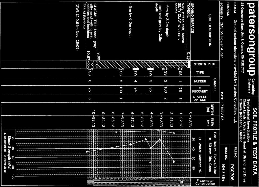
36 patersongroup 28 Concourse Gate, Unit 1, Ottawa, ON K2E 7T7 DATUM REMARKS BORINGS BY Consulting Engineers Clarke Lands Stage 1 Development Ottawa, Ontario TBM - Cut cross in concrete slab, east side of Kennedy Burnett Drain at Strandherd Drive. Geodetic elevation = m. CME 55 Power Auger DATE SOIL PROFILE AND TEST DATA 16 December 2009 FILE NO. HOLE NO. PG1984 BH 1 SOIL DESCRIPTION GROUND SURFACE TOPSOIL 0.25 STRATA PLOT TYPE AU SAMPLE NUMBER % RECOVERY 1 N VALUE or RQD DEPTH (m) 0 ELEV. (m) Pen. Resist. Blows/0.3m 50 mm Dia. Cone Water Content % Piezometer Construction SS 2 Very stiff, brown to grey SILTY CLAY SS TW Firm, grey SILTY CLAY TW TW Dynamic Cone Penetration Test 8.23m depth. Cone pushed to 10.4m depth TW End of Borehole Practical DCPT 13.31m depth (Piezometer blocked - Jan. 12/10) Shear Strength (kpa) Undisturbed Remoulded
37 patersongroup 28 Concourse Gate, Unit 1, Ottawa, ON K2E 7T7 DATUM REMARKS Consulting Engineers Clarke Lands Stage 1 Development Ottawa, Ontario TBM - Cut cross in concrete slab, east side of Kennedy Burnett Drain at Strandherd Drive. Geodetic elevation = m. BORINGS BY CME 55 Power Auger DATE 16 December 2009 SOIL PROFILE AND TEST DATA FILE NO. HOLE NO. PG1984 BH 2 SOIL DESCRIPTION GROUND SURFACE TOPSOIL 0.25 STRATA PLOT TYPE AU SAMPLE NUMBER % RECOVERY 1 N VALUE or RQD DEPTH (m) 0 ELEV. (m) Pen. Resist. Blows/0.3m 50 mm Dia. Cone Water Content % Piezometer Construction Very stiff to stiff, brown to grey SILTY CLAY SS SS TW TW Firm, grey SILTY CLAY TW TW Dynamic Cone Penetration Test 9.04m depth. Cone pushed to 11.3m depth End of Borehole Practical DCPT 14.88m depth 1.20m-Jan. 12/10) Shear Strength (kpa) Undisturbed Remoulded
38 patersongroup 28 Concourse Gate, Unit 1, Ottawa, ON K2E 7T7 DATUM REMARKS BORINGS BY Consulting Engineers Clarke Lands Stage 1 Development Ottawa, Ontario TBM - Cut cross in concrete slab, east side of Kennedy Burnett Drain at Strandherd Drive. Geodetic elevation = m. CME 55 Power Auger DATE SOIL PROFILE AND TEST DATA 16 December 2009 FILE NO. HOLE NO. PG1984 BH 3 SOIL DESCRIPTION GROUND SURFACE TOPSOIL 0.30 STRATA PLOT TYPE AU SAMPLE NUMBER % RECOVERY 1 N VALUE or RQD DEPTH (m) 0 ELEV. (m) Pen. Resist. Blows/0.3m 50 mm Dia. Cone Water Content % Piezometer Construction Very stiff to stiff, brown to grey SILTY CLAY SS SS TW TW Firm, grey SILTY CLAY TW TW Dynamic Cone Penetration Test 9.04m depth. Cone pushed to 11.9m depth End of Borehole Practical DCPT 13.31m depth 1.20m-Jan. 12/10) Shear Strength (kpa) Undisturbed Remoulded
39 patersongroup 28 Concourse Gate, Unit 1, Ottawa, ON K2E 7T7 DATUM REMARKS BORINGS BY Consulting Engineers Clarke Lands Stage 1 Development Ottawa, Ontario TBM - Cut cross in concrete slab, east side of Kennedy Burnett Drain at Strandherd Drive. Geodetic elevation = m. CME 55 Power Auger DATE SOIL PROFILE AND TEST DATA 17 December 2009 FILE NO. HOLE NO. PG1984 BH 4 SOIL DESCRIPTION GROUND SURFACE TOPSOIL 0.30 STRATA PLOT TYPE AU SAMPLE NUMBER % RECOVERY 1 N VALUE or RQD DEPTH (m) 0 ELEV. (m) Pen. Resist. Blows/0.3m 50 mm Dia. Cone Water Content % Piezometer Construction SS Very stiff to stiff, brown to grey SILTY CLAY SS TW TW Firm, grey SILTY CLAY TW TW Dynamic Cone Penetration Test 9.04m depth. Cone pushed to 11.0m depth End of Borehole Practical DCPT 13.34m depth 3.30m-Jan. 12/10) Shear Strength (kpa) Undisturbed Remoulded
40 patersongroup 28 Concourse Gate, Unit 1, Ottawa, ON K2E 7T7 DATUM REMARKS BORINGS BY Consulting Engineers Clarke Lands Stage 1 Development Ottawa, Ontario TBM - Cut cross in concrete slab, east side of Kennedy Burnett Drain at Strandherd Drive. Geodetic elevation = m. CME 55 Power Auger DATE SOIL PROFILE AND TEST DATA 17 December 2009 FILE NO. HOLE NO. PG1984 BH 5 SOIL DESCRIPTION GROUND SURFACE TOPSOIL 0.30 STRATA PLOT TYPE AU SAMPLE NUMBER % RECOVERY 1 N VALUE or RQD DEPTH (m) 0 ELEV. (m) Pen. Resist. Blows/0.3m 50 mm Dia. Cone Water Content % Piezometer Construction SS Very stiff to stiff, brown to grey SILTY CLAY SS TW TW Firm, grey SILTY CLAY TW TW Dynamic Cone Penetration Test 9.04m depth. Cone pushed to 11.3m depth End of Borehole Practical DCPT 12.01m depth 1.10m-Jan. 12/10) Shear Strength (kpa) Undisturbed Remoulded
41 patersongroup 28 Concourse Gate, Unit 1, Ottawa, ON K2E 7T7 DATUM REMARKS BORINGS BY Consulting Engineers Clarke Lands Stage 1 Development Ottawa, Ontario TBM - Cut cross in concrete slab, east side of Kennedy Burnett Drain at Strandherd Drive. Geodetic elevation = m. CME 55 Power Auger DATE SOIL PROFILE AND TEST DATA 17 December 2009 FILE NO. HOLE NO. PG1984 BH 6 SOIL DESCRIPTION GROUND SURFACE TOPSOIL 0.30 STRATA PLOT TYPE AU SAMPLE NUMBER % RECOVERY 1 N VALUE or RQD DEPTH (m) 0 ELEV. (m) Pen. Resist. Blows/0.3m 50 mm Dia. Cone Water Content % Piezometer Construction SS Very stiff to stiff, brown to grey SILTY CLAY SS TW TW Firm, grey SILTY CLAY TW TW Dynamic Cone Penetration Test 9.04m depth. Cone pushed to 11.0m depth End of Borehole Practical DCPT 14.43m depth (Piezometer destroyed - Jan. 12/10) Shear Strength (kpa) Undisturbed Remoulded
42

43

44


45


46
47


48


49
50 SYMBOLS AND TERMS SOIL DESCRIPTION Behavioural properties, such as structure and strength, take precedence over particle gradation in describing soils. Terminology describing soil structure are as follows: Desiccated - having visible signs of weathering by oxidation of clay minerals, shrinkage cracks, etc. Fissured - having cracks, and hence a blocky structure. Varved - composed of regular alternating layers of silt and clay. Stratified - composed of alternating layers of different soil types, e.g. silt and sand or silt and clay. Well-Graded - Having wide range in grain sizes and substantial amounts of all intermediate particle sizes (see Grain Size Distribution). Uniformly-Graded - Predominantly of one grain size (see Grain Size Distribution). The standard terminology to describe the strength of cohesionless soils is the relative density, usually inferred from the results of the Standard Penetration Test (SPT) N value. The SPT N value is the number of blows of a 63.5 kg hammer, falling 760 mm, required to drive a 51 mm O.D. split spoon sampler 300 mm into the soil after an initial penetration of 150 mm. Relative Density N Value Relative Density % Very Loose <4 <15 Loose Compact Dense Very Dense >50 >85 The standard terminology to describe the strength of cohesive soils is the consistency, which is based on the undisturbed undrained shear strength as measured by the in situ or laboratory vane tests, penetrometer tests, unconfined compression tests, or occasionally by Standard Penetration Tests. Consistency Undrained Shear Strength (kpa) N Value Very Soft <12 <2 Soft Firm Stiff Very Stiff Hard >200 >30
51 SYMBOLS AND TERMS (continued) SOIL DESCRIPTION (continued) Cohesive soils can also be classified according to their sensitivity. The sensitivity is the ratio between the undisturbed undrained shear strength and the remoulded undrained shear strength of the soil. Terminology used for describing soil strata based upon texture, or the proportion of individual particle sizes present is provided on the Textural Soil Classification Chart at the end of this information package. ROCK DESCRIPTION The structural description of the bedrock mass is based on the Rock Quality Designation (RQD). The RQD classification is based on a modified core recovery percentage in which all pieces of sound core over 100 mm long are counted as recovery. The smaller pieces are considered to be a result of closelyspaced discontinuities (resulting from shearing, jointing, faulting, or weathering) in the rock mass and are not counted. RQD is ideally determined from NXL size core. However, it can be used on smaller core sizes, such as BX, if the bulk of the fractures caused by drilling stresses (called mechanical breaks ) are easily distinguishable from the normal in situ fractures. RQD % ROCK QUALITY Excellent, intact, very sound Good, massive, moderately jointed or sound Fair, blocky and seamy, fractured Poor, shattered and very seamy or blocky, severely fractured 0-25 Very poor, crushed, very severely fractured SAMPLE TYPES SS - Split spoon sample (obtained in conjunction with the performing of the Standard Penetration Test (SPT)) TW - Thin wall tube or Shelby tube PS - Piston sample AU - Auger sample or bulk sample WS - Wash sample RC - Rock core sample (Core bit size AXT, BXL, etc.). Rock core samples are obtained with the use of standard diamond drilling bits.
52 SYMBOLS AND TERMS (continued) GRAIN SIZE DISTRIBUTION MC% - Natural moisture content or water content of sample, % LL - Liquid Limit, % (water content above which soil behaves as a liquid) PL - Plastic limit, % (water content above which soil behaves plastically) PI - Plasticity index, % (difference between LL and PL) Dxx - Grain size which xx% of the soil, by weight, is of finer grain sizes These grain size descriptions are not used below mm grain size D10 - Grain size at which 10% of the soil is finer (effective grain size) D60 - Grain size at which 60% of the soil is finer Cc - Concavity coefficient = (D30) 2 / (D10 x D60) Cu - Uniformity coefficient = D60 / D10 Cc and Cu are used to assess the grading of sands and gravels: Well-graded gravels have: 1 < Cc < 3 and Cu > 4 Well-graded sands have: 1 < Cc < 3 and Cu > 6 Sands and gravels not meeting the above requirements are poorly-graded or uniformly-graded. Cc and Cu are not applicable for the description of soils with more than 10% silt and clay (more than 10% finer than mm or the #200 sieve) CONSOLIDATION TEST p o - Present effective overburden pressure at sample depth p c - Preconsolidation pressure of (maximum past pressure on) sample Ccr - Recompression index (in effect at pressures below p c ) Cc - Compression index (in effect at pressures above p c ) OC Ratio Overconsolidaton ratio = p c / p o Void Ratio Initial sample void ratio = volume of voids / volume of solids Wo - Initial water content (at start of consolidation test) PERMEABILITY TEST k - Coefficient of permeability or hydraulic conductivity is a measure of the ability of water to flow through the sample. The value of k is measured at a specified unit weight for (remoulded) cohesionless soil samples, because its value will vary with the unit weight or density of the sample during the test.
53
54 APPENDIX 2 Table 1 - Summary of Subsurface Information Table 2 - Summary of Consolidation Test Results Consolidation Test Sheets Atterberg Limits Results Shear Strength Profile - Clarke Lands - Stage 1
55 Table 1 Summary of Subsurface Information for Clarke Lands Stage 1 Strandherd Road at Kennedy Burnett Drain - Ottawa Test Hole Number Ground Elevation (m) Underside of Stiff Clay Crust Underside of Clay Inferred Bedrock Surface Level Depth (m) Elevation (m) Depth (m) Elevation (m) Depth (m) Elevation (m) BH BH BH BH BH BH BH >10.67 BH >12.8 BH >10.52 BH BH >10.06 BH >11.28 BH >12.80 BH >11.28 Note: 1. Inferred bedrock surface is the depth of practical refusal of the dynamic cone penetration test (DCPT). All other boreholes terminated in an inferred glacial till stratum.
56 Table 2 Summary of Consolidation Test Results - Clarke Lands Stage 1 Strandherd Road at Kennedy Burnett Drain - Ottawa Sample No. Ground Elev. (m) Depth (m) Elevation (m) p' c (kpa) p' o (kpa) O.C. (kpa) Ccr Cc W.C. (%) Sample Quality Clarke Lands Stage Testing Program: BH1 - TW A BH2 - TW A BH3 - TW P BH4 - TW A BH5 - TW A BH6 - TW P Clarke Lands Preliminary Testing Program: BH TW F BH TW G BH TW G Barrhaven Mews & 2007 Testing Programs: BH TW P BH TW A BH TW G Notes: 1. Effective overburden pressure, p' o, is based on an average long-term low groundwater depth of 2.5m and average crust thickness of 3.0 m. 2. The last column presents the quality assessment of the test sample: G = Good A = Acceptable P = Poor (Likely Disturbed)
57 V O ID R A TI O STRESS, kpa Borehole No. Sample No. CONSOLIDATION TEST DATA SUMMARY BH 1 p' o 57 kpa Ccr TW 5 p' c 90 kpa Cc Sample Depth Sample Elev m m OC Ratio Void Ratio Wo Unit Wt % kn/m 3 CLIENT Minto Communities Inc. PROJECT - Clarke Lands Stage 1 Development patersongroup 28 Concouse Gate, Unit 1, Ottawa, Ontario K2E 7T7 Consulting Engineers FILE NO. PG1984 DATE 01/11/10 CONSOLIDATION TEST
58 V O ID 1.75 R A TI O STRESS, kpa Borehole No. Sample No. CONSOLIDATION TEST DATA SUMMARY BH 2 p' o 57 kpa Ccr TW 5 p' c 113 kpa Cc Sample Depth Sample Elev. 4.9 m OC Ratio 2.0 Wo m Void Ratio Unit Wt % kn/m 3 CLIENT Minto Communities Inc. PROJECT - Clarke Lands Stage 1 Development patersongroup 28 Concouse Gate, Unit 1, Ottawa, Ontario K2E 7T7 Consulting Engineers FILE NO. PG1984 DATE 01/12/10 CONSOLIDATION TEST
59 V O ID 1.85 R A TI O STRESS, kpa Borehole No. Sample No. CONSOLIDATION TEST DATA SUMMARY BH 3 p' o 57 kpa Ccr TW 5 p' c 105 kpa Cc Sample Depth Sample Elev m m OC Ratio Void Ratio Wo Unit Wt % 15.5 kn/m 3 CLIENT Minto Communities Inc. PROJECT - Clarke Lands Stage 1 Development patersongroup 28 Concouse Gate, Unit 1, Ottawa, Ontario K2E 7T7 Consulting Engineers FILE NO. PG1984 DATE 01/06/10 CONSOLIDATION TEST
60 V O ID 1.8 R A TI O STRESS, kpa Borehole No. Sample No. CONSOLIDATION TEST DATA SUMMARY BH 4 p' o 66 kpa Ccr TW 6 p' c 107 kpa Cc Sample Depth Sample Elev m m OC Ratio Void Ratio Wo Unit Wt % kn/m 3 CLIENT Minto Communities Inc. PROJECT - Clarke Lands Stage 1 Development patersongroup 28 Concouse Gate, Unit 1, Ottawa, Ontario K2E 7T7 Consulting Engineers FILE NO. PG1984 DATE 01/12/10 CONSOLIDATION TEST
61 V O ID 1.74 R A TI O STRESS, kpa Borehole No. Sample No. CONSOLIDATION TEST DATA SUMMARY BH 5 TW 6 p' o p' c kpa kpa Ccr Cc Sample Depth Sample Elev m m OC Ratio Void Ratio Wo Unit Wt % kn/m 3 CLIENT Minto Communities Inc. PROJECT - Clarke Lands Stage 1 Development patersongroup 28 Concouse Gate, Unit 1, Ottawa, Ontario K2E 7T7 Consulting Engineers FILE NO. DATE PG /08/10 CONSOLIDATION TEST
62 V O ID R A TI O STRESS, kpa Borehole No. Sample No. CONSOLIDATION TEST DATA SUMMARY BH 6 p' o 57 kpa Ccr TW 5 p' c 101 kpa Cc Sample Depth Sample Elev. 4.9 m OC Ratio 1.8 Wo m Void Ratio 1.92 Unit Wt % kn/m 3 CLIENT Minto Communities Inc. PROJECT - Clarke Lands Stage 1 Development patersongroup 28 Concouse Gate, Unit 1, Ottawa, Ontario K2E 7T7 Consulting Engineers FILE NO. PG1984 DATE 01/12/10 CONSOLIDATION TEST


63


64


65
66 60 CL CH P L A S T I C I T Y I N D E X CL-ML ML MH LIQUID LIMIT (LL) Specimen Identification LL PL PI Fines Classification BH 2 BH 5 TW 5 TW CH-Inorganic clays of high plasticity CH-Inorganic clays of high plasticity CLIENT Minto Communities Inc. PROJECT - Clarke Lands Stage 1 Development patersongroup Consulting Engineers 28 Concouse Gate, Unit 1, Ottawa, Ontario K2E 7T7 FILE NO. DATE PG Dec 09 ATTERBERG LIMITS' RESULTS
67 Shear Strength Profile - Clarke Lands - Stage BH 1 BH 2 Geodetic Elevation (m) BH 3 BH 4 BH 5 BH 6 BH 7-05 BH 8-05 BH 9-05 BH 1-06 BH 2-06 BH 7-07 BH BH Undrained Shear Strength - Cu (kpa) Report No. PG September 23, 2010 patersongroup
68 APPENDIX 3 Figure 1 - Key Plan Drawing PG Test Hole Location Plan

69 FIGURE 1 KEY PLAN SITE