LIGHT-GAUGE PANELIZED WALL SYSTEMS. Michael Waggoner Mark Schroeder
|
|
|
- Bennett Burke
- 5 years ago
- Views:
Transcription
1 LIGHT-GAUGE PANELIZED WALL SYSTEMS Michael Waggoner Mark Schroeder
2 INTRODUCTION Development of Light-Gauge Panelized Wall Systems Selecting the Right Framing Systems Building Code Design Considerations Panel Design and Construction Example Project The Palms Las Vegas, Nevada
3 DEVELOPMENT OF LIGHT-GAUGE PANELIZED WALL SYSTEMS Design-Build Evolution - Competitive design and construction environment reduces overall cost - Façade design can occur later in the design process Construction Considerations - High-rise scaffolding costs - Schedule driven projects - Immediate exterior cladding to allow for interior build-out - Shared crane time between G.C. and light-gauge subcontractors
4 SELECTING THE RIGHT FRAMING SYSTEM Building System vs. Finish System Vertical Deformation Compatibility with Base Structure Lateral Serviceability Deformation Compatibility with Base Structure
5 Selecting the Right Framing System BUILDING SYSTEMS VS. FINISH SYSTEMS BUILDING SYSTEMS Steel Moment Frames Concrete Moment Frames Eccentric Braced Frames Concentric Braced Frames Concrete Shear Walls FLEXIBLE SYSTEMS FINISH SYSTEMS EIFS Systems Cement Plaster Systems Adhered Veneer Systems Anchored Veneer and Stone Systems RIGID SYSTEMS
6 Selecting the Right Framing System VERTICAL DEFORMATION COMPATABILITY Horizontal Expansion Joint Locations - Floor lines - Window heads - Window sills - Reveals Vertical Expansion Components - Slip Clips; Slotted Slip Track; Quick Clips; Pin Connections Panel Considerations - Single level panels - Double level panels - Spandrel panels - Balcony panels
7 Selecting the Right Framing System LATERAL SERVICEABILITY DEFORMATION COMPATABILITY Thermal Expansion and Contraction Finish Material Shrinkage: Control Joints Concrete Building Shrinkage The Role of Vertical Expansion Joints Flexible Connections Seismic Drift
8 In-plane Design - Seismic Loads - Seismic Drift BUILDING CODE DESIGN CONSIDERATIONS Out-of-plane Design - Wind Loads - Panel Lift - Deflection Criteria
9 Building Code Design Considerations IN-PLANE DESIGN LOADS 1997 Uniform Building Code Seismic Design Loads ( ) F p = a pc a I p R p a p = 1.0 h x h r R p = 3.0 (Members and bodies of connections) R p = 1.0 (Fasteners in the connecting system) Loads Increase with Building Height
10 Building Code Design Considerations IN-PLANE DESIGN DRIFT 1997 Uniform Building Code Drift Provisions /R x H = Anticipated Drift (Approximately H to H) Code Introduces D M - Limits in Ultimate Plastic Drift Placed at H
11 Building Code Design Considerations IN-PLANE DESIGN DRIFT 1997 Uniform Building Code Comparison to Previous Codes - Comparison: H versus H x 3R/ H versus H - An Increase in Anticipated Maximum Drift of 70% Anticipate More Damage
12 Building Code Design Considerations SEAOC BLUE BOOK COMMENTARY Structures designed in conformance with these recommendations should, in general, be able to: 1. Resist a minor level of earthquake motion without damage; 2. Resist a moderate level of earthquake ground motion without structural damage, but possibly experience some nonstructural damage. 3. Resist a major level of earthquake ground motion having intensity equal to the strongest either experienced or forecast for the building site, without collapse, but possibly with some structural as well as nonstructural damage.
13 Building Code Design Considerations SEAOC BLUE BOOK COMMENTARY The primary function of these recommendations is to provide minimum standards for use in building design regulation to maintain public safety in the extreme earthquakes likely to occur at the building s site. These recommendations primarily are intended to safeguard against major failures and loss of life, not to limit damage, maintain functions, or provide for easy repair. It is emphasized that the purpose of these recommended design procedures is to provide buildings that are expected to meet this life safety objective.
14 Building Code Design Considerations SEAOC BLUE BOOK COMMENTARY Exterior Elements. Exterior nonbearing, nonshear wall panels or elements that are attached to enclose the exterior shall be designed to resist the forces per Formula (32-1) or (32-2) and shall accommodate the movements of the structure based upon D M and temperature changes. Such elements shall be supported by means of cast-in-place concrete or by mechanical connections and fasteners in accordance with the following provisions: 1. Connections and panel joints shall allow for relative movement between stories 2. Connections to permit movement in the plane of the panel for story drift shall be sliding connections using slotted or oversize holes, connections that permit movement by bending of steel or other connections providing equivalent sliding and ductility capacity.
15 Building Code Design Considerations OUT-OF-PLANE DESIGN LOADS 1997 Uniform Building Code Wind Loads P = C e C q q s I w C q = 1.2 (Elements not in areas of discontinuity) C q = 1.0 (Elements in areas of continuity) Loads Remain Constant with Building Height
16 Building Code Design Considerations OUT-OF-PLANE DESIGN LOADS Impact for Lift Load - Impact factor = Very short term load - Consider additional stiffness due to finishes when possible - Windows not installed - Load duration factor = 1.33
17 Maximum Stud Length (ft) L/240 Consideration " x 16 ga 6" x 16 ga 8" x 16 ga Note: 16" o.c Wind Pressure (psf)
18 Maximum Stud Length (ft) L/360 Consideration " x 16 ga 6" x 16 ga 8" x 16 ga Note: 16" o.c Wind Pressure (psf)
19 Maximum Stud Length (ft) L/600 Consideration " x 16 ga 6" x 16 ga 8" x 16 ga Note: 16" o.c Wind pressure (psf)
20 Maximum Stud Length (ft) L/720 Consideration " x 16 ga 6" x 16 ga 8" x 16 ga Note: 16" o.c Wind Pressure (psf)
21 PANEL DESIGN AND CONSTRUCTION Example Project The Palms Las Vegas, Nevada ft tower - Concrete shear wall building - EIFS exterior insulating finish system - Fast schedule - 2 levels high and 2 room units wide


22 PANEL DESIGN AND CONSTRUCTION The Palms Las Vegas, Nevada
23 PANEL DESIGN AND CONSTRUCTION Panel Yard Panel Layout Embed Layout Panel Top Connection Panel Bottom Connection Panel Mid-Level Connection Panel Erection Sequence Other Panel Configurations
24 PANEL YARD Panel Yard Requirements - Proximity to site - Panel yard size - Weather Panel Yard Activities - Panel framing - Panel Sheathing - EIFS wrap - Painting and/or finishing - Storage

25 PANEL YARD The Palms Panel Yard

26 PANEL YARD The Palms Panel Yard
27 PANEL LAYOUT Panel Layout on Building - Panels types identified - Intelligent panel numbering system used Individual Panel Layout - Computer generated dimensioning - Shop drawing production - Small dimensional errors can create significant field issues
28 PANEL LAYOUT
29 PANEL LAYOUT
30 PANEL LAYOUT
31 EMBED LAYOUT Embeds Installed by General Contractor - Part of concrete pour - Early submittal - Dimensions must be verified Embeds Must Accommodate Base Structure - Post-tensioning anchor locations - Different layout for odd and even floors» Intermittent plates» Continuous angles
32 Bottom Panel Gravity Connection EMBED LAYOUT
33 Bottom Panel Gravity Connection EMBED LAYOUT
34 EMBED LAYOUT
35 EMBED LAYOUT
36 PANEL BOTTOM CONNECTION Panel Bottom Connection - Panels bear on shelf angle - Shelf angle welded to embed plates - Bottom connection takes 2 levels of gravity load - Bottom connection takes 1 level of wind load
37 PANEL BOTTOM CONNECTION
38 PANEL TOP CONNECTION Drift Calculations for Slotted Top Connection - Determine shear wall capacity - Assume cracked section properties - Back calculate drift - Determine D M Pin Connection - Allows in-plane movement - Restrains out-of-plane movement - Oversize hole in light-gauge track - Slotted hole in structural plate
39 PANEL TOP CONNECTION
40 PANEL MID-LEVEL CONNECTION Slip-Clip Connection - Allows for vertical movement - Provides flexible and ductile behavior - helps resist lateral in-plane load - Resists 1 level of out-of-plane load - Must be installed after panel is in place - Every other clip preferred Other Conditions - Accessibility
41 PANEL MID-LEVEL CONNECTION

42 PANEL MID-LEVEL CONNECTION Mid-Level Connection

43 PANEL MID-LEVEL CONNECTION Mid Level Connection at Shear Wall

44 PANEL MID-LEVEL CONNECTION Mid Level Connection at Shear Wall
45 PANEL MID-LEVEL CONNECTION
46 PANEL ERECTION SEQUENCE Typical Erection Sequence (2 story panel) - Field verify all building and panel dimensions - Install shelf angle at bottom connection - Place panel on shelf angles with pin alignments - Set in-out and in-plane alignment - Install temporary top connector - Install pin-connection washers at lower panels - Remove temporary top connector from panel below - Install mid-level connectors
47 PANEL ERECTION SEQUENCE Install temporary Field verify building top connector and panel Install Place panel above dimensions shelf angle for at bottom Set on in-out shelf and angles inplane with alignment pin panel above connection alignments Field verify all building and panel Remove Place temporary Install mid-level panel dimensions top connector connectors shelf angles from with panel below pin alignments Install pin-connection washers at lower panels Install shelf angle at bottom connection

48 PANEL ERECTION SEQUENCE Panel Placement and In-Out Alignment

49 PANEL ERECTION SEQUENCE In-Plane Alignment
50 PANEL LIFT CONSIDERATIONS Panel Lift considerations - Reusable lift lugs - 2 to 4 connection points per panel - Spreader frame used for evenly distributed panel lift
51 PANEL LIFT CONSIDERATIONS
52 PANEL LIFT CONSIDERATIONS
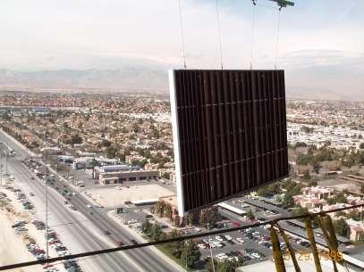
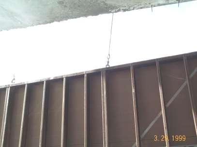
53 PANEL LIFT CONSIDERATIONS The Palms Las Vegas, Nevada
54 OTHER PANEL CONFIGURATIONS Curved Panels Balcony Panels Spandrel Panels Sign Supports

55 OTHER PANEL CONFIGURATIONS Polo Towers Las Vegas, Nevada