Detailed Deck Building
|
|
|
- Brice Wells
- 5 years ago
- Views:
Transcription


1 Detailed Deck Building PERMITS REQUIREMENTS. Building permits are required for all decks attached to a structure. Building permits can be obtained from the Building Department by filling out an application and submitting with your building plans. Permit value is based on project value. Building permits are typically processed within 2-3 business days of receiving the application and a complete, accurate set of plans. A Zoning permit is required for freestanding decks that are not part of a required egress route, if they are more than 30 inches above adjacent grade. See Zoning Regulations below. Freestanding decks do not require footings that extend below the 42 frost depth. Patios made of concrete or pavers on grade also require a Zoning permit. PLAN REQUIREMENTS. The Building Department has a handout illustrating what needs to be included on deck plans. It is very important that your plans depict exactly how your deck will be built. Plans must be neat and be to a scale of at least ¼ = 1. Computer generated plans from home stores are not acceptable as is. Plans are reviewed for code compliance and a copy is returned to the applicant with notes to identify required corrections. CAREFULLY REVIEW THE PLANS WHEN THEY ARE RETURNED TO YOU SO THAT YOU WILL BE AWARE OF ANY NOTES MADE OR CORRECTIONS NEEDED. PERMIT EXPIRATION. If you suspend work on your deck for more than 180 days since permit issuance or your last inspection, your permit will expire. If circumstances delay construction, contact the Building Department before your permit expires. INSPECTIONS PROCESS 1. Call at least 24 hours in advance. 2. Have address, permit number, and type of inspection (ex. footing) ready. 3. Let scheduler know if you wish an exact time. The minimum 2 required inspections are: A.) Footing Inspection - Holes dug, loose material/water removed, bottom tamped. Plans and record card on-site. B.) Final Inspection - All work complete and all stairs, handrails, and guards in place. Plans and record card on-site. Installation instructions for composite decking must be on site. 6. If work is approved, the inspector will sign the record card and you may proceed with the next step. 7. If corrections are noted, a correction notice will be left on the site. If a re-inspection is required it will be noted. THINK YOU MIGHT ENCLOSE YOUR DECK IN THE FUTURE? Deck plans are reviewed on the assumption that the deck will be used only as a deck for the life of the structure, unless otherwise noted. It is important to indicate on the plans if you desire to convert the deck at a future date. Many components are different for enclosed porches including: roof and wall load considerations, setback requirements, footing sizes, structural load supports, etc. ZONING REGULATIONS. Attached decks shall be considered part of the principle structure and shall be subject to the setbacks of the principle structure. Easements, wetland buffers, and other lot restrictions may require greater setbacks than permitted by the zoning ordinance. The most restrictive setback applies. Questions regarding zoning regulations should be directed to the Community Development Dept. at It s FREE and required by law- Contact Before Digging! / / This handout is intended only as a guide and is based in part on the 2015 Minnesota Residential Codes, Mounds View City ordinances, and good building practice. While every attempt has been made to insure the correctness of this handout, no guarantees are made to its accuracy or completeness. Responsibility for compliance with applicable codes and ordinances falls on the owner or contractor. For specific questions refer to the applicable codes or contact the Community Development Department Mounds View Blvd * Mounds View, MN Phone: Website: Permits@moundsviewmn.org


2 Page 2 Locate property pins to ensure accurate lot lines and set back requirements are met.
")
3 Minimum Footing Sizes & Beam Sizing Chart *Mounds View soils typically fall in the sand soil type (center column) Page 3


4 FOOTINGS Consult the Chart on page 3 for required footing sizes- the middle gray column specifies sizes for Mounds View Soils. Footings/pier supporting a 4x4 column must be not less than 6 diameter. Post footings supporting columns larger than 4x4 must be 8-inch diameter or larger. The bottom of post footings may be belled to achieve the desired minimum bearing area. The base of the footing must be at least 42 below finished grade. Rebar is recommended but not usually required. Center the column on the footing secured by a pin or connector. Posts imbedded in the ground must be 60% C.C.A. or equal. Using a fiberboard tube will allow elevation of the top of the footing above finished grade to provide protection of the wood post with ground separation and from lawn mowers, trimmers, etc. THE REQUIRED AREA OF THE COLLUMN SHOULD FULLY BEAR ON THE FOOTING/PIER The minimum compressive strength of concrete used for deck footings is 5000 psi. Post base is required to be anchored to post by approved method to prevent post movement Belling the footing bottom is required if column is not min. width of footing Crowning is a recommended method, but not required Page 4
 Size Square feet of deck supported 36 48 60 72 84 96 108 120 132 144 156 165 180 192 4x4 10 10 10 9 9 8 8 7 7 6 6 6 6 6 4x6 14 14 13")
5 POSTS & COLUMNS Posts are sized based on the deck height, the number of posts and distances apart, and the square footage area of the deck (amount of weight) that each post carries. Species Southern Pine Redwood, Cedar Maximum Post Height (in feet) Size Square feet of deck supported x x x x N/A N/A N/A N/A 4x x N/A N/A N/A N/A N/A N/A 1.) MATERIALS DECK FRAMING Fasteners: Nails and other hardware must be hot-dipped zinc-coated (galvanized), stainless steel or equal. Screws should be either hot-dipped galvanized or electroplated with a polymer coating. 12d nails are recommended on nominal 2- inch decking. 10d nails are recommended for 5/4" decking. With lag screws, use a flat washer under the head. Use washers under the nut and head of machine bolts and just under the nut of carriage bolts. Framing Lumber: All wood used in deck construction must be pressure treated lumber or wood that is naturally resistant to decay, such as redwood or cedar. Wood used in contact with the ground or below ground requires different degrees of treatment. Check the labels of the material you are buying to determine where it can be used. Because some preservative treatments are very corrosive, make sure that any fasteners or metal connectors used in the construction of your deck are approved by the manufacturer for use with treated wood Page 5
 has been specifically developed for outdoor decks.")
6 Decking: Materials commonly used for decking include standard dimension lumber (either 2X4 or 2X6), radius-edged decking, or a manufactured decking product. Radius-edged Patio Decking (5/4 decking) has been specifically developed for outdoor decks. Redwood and cedar patio decking is intended to be used flat-wise in load-bearing applications where spans do not exceed 16" o.c. (12 o.c. when installed diagonally to joists). Southern pine decking may span 24 o.c. or 16 o.c. when installed diagonally to joists Rev. 1/27/2015 Manufactured (composite) decking products may be used only when meeting ASTM D 7032 or when approved by the Building Department. Approval is based on the material carrying an ICC Evaluation Services Report or similar. Decking without a report cannot not be approved. Ask the decking supplier to provide you with a copy of the research report. The Building Department maintains a list of composite decking materials that meet US building codes that is available upon request. Caution some manufactured deck products are approved for decking, but not for stair treads. In some cases where manufactured decking is approved for stairs, the spacing of supports may be significantly reduced compared to use on the deck itself. Read the research report for further information. 2.) LEDGER BOARD (Make sure the ledger is securely attached to the dwelling. Install metal flashing at top and caulk all sides, seams, bottom) TABLE R507.2 FASTENER SPACING FOR A SOUTHERN PINE OR HEM-FIR DECK LEDGER AND A 2-INCH-NOMINAL SOLID-SAWN SPRUCE-PINE-FIR BAND JOIST (c, f, and g) (Deck live load = 40 psf, deck dead load = 10 psf) JOIST SPAN Under to to to to to to 18 Connection details On-center spacing of fasteners (d and e) ½ inch diameter lag screw with 15/32 inch max. sheathing (a) ½ inch diameter bolt with 15/32 inch maximum sheathing ½ inch diameter bolt with 15/32 inch maximum sheathing and ½ inch stacked washers (b, h) a. The tip of the lag screw shall fully extend beyond the inside face of the band joist. b. The maximum gap between the face of the ledger board and face of the wall sheathing shall be ½ inch. c. Ledgers shall be flashed to prevent water from contacting the house band joist. d. Lag screws and bolts shall be staggered in accordance with Section R e. Deck ledger shall be minimum 2 8 pressure-preservative-treated No. 2 grade lumber, or other approved materials as established by standard engineering practice. f. When solid-sawn pressure-preservative-treated deck ledgers are attached to a minimum 1-inch-thick engineered wood product (structural composite lumber, laminated veneer lumber or wood structural panel band joist), the ledger attachment shall be designed in accordance with accepted engineering practice. g. A minimum 1 9½ Douglas Fir laminated veneer lumber rimboard shall be permitted in lieu of the 2-inch nominal band joist. h. Wood structural panel sheathing, gypsum board sheathing or foam sheathing not exceeding 1 inch in thickness shall be permitted. The maximum distance between the face of the ledger board and the face of the band joist shall be 1 inch. Capacity of lag or carriage bolts shall not exceed 400 lb s per bolt unless design provided. Page 6


 4.")
 SOUTHERN PINE WESTERN CEDAR/PONDEROSA PINE 12 oc 16\" oc 24\" oc 12\" oc 16\" oc 24\" oc 2x6 10'4\" 9'5\" 7'10\" 8'10\" 8' 7' 2x8 13'8\"")
7 Flashing Install flashing at the top of the ledger Sealing Seal all sides of the ledger board with an approved caulk AN ALTERNATIVE TO HAVING A DECK SUPPORTED ON THE DECK LEDGER ATTACHED TO HOUSE- THE DECK MAY BE DESIGNED TO BE SELF SUPPORTING, OR A DESIGN MAY BE PROVIDED BY A LICENSED DESIGN PROFESSIONAL 3.) BEAMS Beam sizes and spans must conform with the chart on page 3. Construct beams using two or more 2 nominal pieces of lumber. Nail beams together using 10d nails at 32 inches o.c. along each edge of the beam and staggered. Treated 2X spacers may be used to fir the beam to a wider width. Beams should be installed with any arch or crown facing up. Attachments to columns should be with post caps designed for such use. Splices must occur over posts. BEAM Beam Span (between posts) 4.) JOISTS JOIST SIZE JOIST SPANS (Wet Service) (Source AF&PA; rev ) SOUTHERN PINE WESTERN CEDAR/PONDEROSA PINE 12 oc 16" oc 24" oc 12" oc 16" oc 24" oc 2x6 10'4" 9'5" 7'10" 8'10" 8' 7' 2x8 13'8" 12'5" 10'2" 11'8" 10'7" 8'8" 2x10 17'5" 15'10" 13'5" 14'11" 13' 10'7" 2x12 21'2" 18'10" 15'5" 17'5" 15'1" 12'4" Page 7


8 Overlap Joists on top of beam and fasten with a minimum of 3 10d fasteners, or with a tie strap Overlap splices a minimum of 3 Joists must bear on a beam, ledger strip, or joist hangers. Joist hangers must be installed in accordance with the manufacturer s recommendations. Use all nail holes in joist hangers. MAXIMUM DECK BOARD SPANS BETWEEN JOISTS 2x6 OR 5/4 SOUTHERN PINE PERPENDICULAR TO JOIST 24 O.C. 2X4 OR 5/4 CEDAR OR REDWOOD PERPENDICULAR TO JOIST 16 O.C. 2X6 OR 5/4 SOUTHERN PINE AT 45 DEGREES TO JOIST 16 O.C. 2X4 OR 5/4 AT 45 DEGRESS TO JOIST 12 O.C. *Composite Materials- Check manufacturer requirements for spacing and spans* Joist spacing is determined in part by the type of decking used, and the installation angle or direction. Page 8


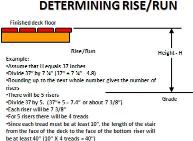
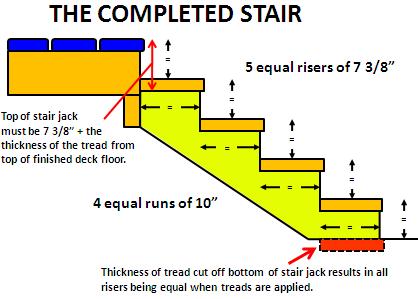
9 5.) STAIRS Stairs must have a maximum rise of 73/4 inches and a minimum run of 10 inches measured as shown. The greatest riser height within any flight of stairs shall not exceed the smallest by more than ⅜ inch. The greatest tread depth within any flight of stairs shall not exceed the smallest by more than ⅜ inch. Open risers are permitted provided that a 4 diameter sphere will not pass between the treads. Stairs must be a minimum of 36 inches wide above the handrail and 31½ inches below the handrail. Double up header or joists where stairs connect to deck for support (see page 11 for stair attachment) Page 9
10 Page 10


11 (Example for a 2 X 12) Min. 4 Stair Attachments HANGERS STRAPS Page 11
 is 36 minimum. Stair guard heights shall be 34 minimum. Handrails incorporated in or attached to guards shall be placed between 34 38.")
12 6.) GUARDS AND HANDRAILS Guards and handrails must be provided as shown on the following illustrations. Guards must continue down stairs where the stair is more than 30 inches above grade. The height of guards for decks (above 30 high) is 36 minimum. Stair guard heights shall be 34 minimum. Handrails incorporated in or attached to guards shall be placed between Spacing of balusters is 4 maximum on deck guards; or 4 3/8 maximum on stair guards. Handrails must be provided on at least one side of stairs when there are four or more risers. Handrails must be continuous for the entire length of the stairs and must have returns on each end or terminate in a newel post. Other handrail shapes having an equivalent gripping shape may be used with prior approval of the Building Department. Handrails and guards must be designed to support a 200 lb load applied in any direction at any point along the top of the guard or rail. It is strongly recommended to use a continuous top rail as in the circled example above, where the top rail runs over the top of the railing posts, rather than having the post interrupt the top railing. This can help add considerable strength to a rail to help it meet the 200 lbs concentrated load requirement. Page 12
, or terminate in a newel post. *Return Graspable Hand Rail options (and code requirements) Page 13")
13 Handrails are required on at least 1 side, must be high, continuous for the entire length of the stairs, and may not be interrupted by newel posts except at landings. Must have *returns on each end (top and bottom), or terminate in a newel post. *Return Graspable Hand Rail options (and code requirements) Page 13


14 ! It is suggested to avoid notching guard posts Page 14
15 Misc. Information MAXIMUM CANTILEVER SPANS FOR JOISTS WITH BACKSPAN AT LEAST 2:1 *The amount of cantilever is limited by the size and spacing of the joist, and the length of the backspan. JOIST SIZE SPACING O.C. MAX. CANTILEVER 2X X X X X X X COMPOSITES AND OTHER DECK/RAILING PRODUCTS Wood/plastic composites used for exterior deck boards, stair treads, handrails and guardrail systems must bear labels indicating compliance with ASTM D 7031 or a current ICC Evaluation Services Report or similar report must be made available. Wood/plastic composites complying with ASTM D 7031 must be installed in accordance with the manufacturer s written installation instructions. Wood/plastic composites having an ICC ES Report must be installed in accordance with the manufacturer s installation instructions and the report. READ THE INSTRUCTIONS AND THE REPORTS CAREFULLY. ALL PRODUCTS HAVE SPECIFIC REQUIREMENTS FOR STAIR TREADS. SOME PRODUCTS REQUIRE INSTALLATION THAT IS PERPENDICULAR TO JOISTS ONLY. PRODUCTS MADE OF ALUMINUM, STEEL, GLASS, OR ANY OTHER MAN MADE PRODUCT MAY BE USED IF THE MANUFACTURER HAS A RESEARCH REPORT FROM THE INTERNATIONAL CODE COUNCIL AND THE PRODUCT IS INSTALLED IN STRICT ACCORDANCE WITH THAT REPORT OR SITE SPECIFIC ENGINEERING IS PROVIDED. Page 15


16 LATERAL LOAD DEVICE CONNECTIONS (NOT REQUIRED) TWO MINIMUM PER DECK (IF USED) HOLD-DOWN TENSION DEVICES MUST BE INSTALLED IN NOT LESS THAN TWO LOCATIONS PER DECK EACH DEVICE MUST HAVE AN ALLOWABLE STRESS DESIGN CAPACITY OF NOT LESS THAN 1500 POUNDS FLOOR SHEATHING IN THE DWELLING MUST BE NAILED TO THE JOISTS TO WHICH HOLD DOWNS ARE CONNECTED AT 6 MAXIMUM O.C. FLOOR JOISTS PERPENDICULAR TO DECK LEDGER ACCESS DOOR TO SPACE ABOVE FINISHED BASEMENT CEILING Page 16