TECHNICAL MANUAL. PEC Column Shoe. Heavy-duty Bolted Column Connections
|
|
|
- Gladys Johns
- 5 years ago
- Views:
Transcription


1 TECHNICAL MANUAL PEC Column Shoe Heavy-duty Bolted Column Connections Version: PEIKKO GROUP 09/2018


2 PEC Column Shoe For bolted column connections Advanced casting process with the help of standard accessories Safe, simple and quick assembly with no bracing and welding Cost-effi cient column erection with reduced man- and crane-hours Increased design effi ciency using Peikko Designer software PEC Column Shoes are connecting items to form fast and safe connections between precast concrete columns and foundations, or between precast concrete columns. PEC Column Shoes are used with PPM High-Strength Anchor Bolts to create moment-resisting column connections under heavy loading conditions. The typical bolted column connection is made by the column shoes and anchor bolts. The column shoes are cast into precast concrete column while anchor bolts are cast into foundation or another column. On construction site the columns are erected on the anchor bolts, adjusted to the correct level and vertical position. Fixing is achieved by tightening the nuts on the anchor bolts. The joint between column and structure below should be grouted before loading the column. After the grout has reached the designed strength the connection acts as reinforced concrete structure. The main advantage in using bolted connections is that an immediate connection is made. Column is installed without temporary bracing only by leveling and tightening the nuts. With a help of standard accessories casting process is quick and easy both at precast factory and construction site. Solution is cost-efficient by final savings coming from reduced excavation depth of the foundation, simplified supplementary reinforcement frame and less man- and crane-hours.
3 Contents About PEC Column Shoe 4 1. Product properties Structural behavior Temporary conditions Final conditions Application conditions Loading and environmental conditions Interaction with column Positioning of the column shoe Other properties Resistances Axial resistance Shear resistance Fire resistance Selecting PEC Column Shoe 12 Annex A Transverse reinforcement in the lap zone and supplementary reinforcement 14 Annex B Alternative use of PEC Column Shoe 16 Installation of PEC Column Shoe 18 Precast factory - Casting of PEC Column Shoe Construction site - Assembling the connection Revision: 001*


 or in the top part of lower column (column to column connection).")


4 About PEC Column Shoe 1. Product properties PEC Column Shoes are available in several standard models to solve the most of precast concrete column connections. The original Peikko Column Connection system consists of: Column shoes Anchor bolts Accessories: recess formers and installation templates PEC Column Shoes are used with PPM High-Strength Anchor Bolts to achieve moment resisting precast concrete column connections. Column Shoes are cast into the bottom part of the column together with main and supplementary reinforcement, detailed in Annex A of this manual. PPM High-Strength Anchor Bolts are either cast into foundation (column to foundation connection) or in the top part of lower column (column to column connection). Column shoe has a round hole that fits with the corresponding anchor bolt. The column connection is achieved by fastening the anchor bolts to column shoes by using nuts and washers. The bolted connection offers sufficient assembly tolerances to adjust the column at the correct level and vertical position. To finalize the connection, the joint underneath the column and recesses are grouted with non-shrink grout material. Column Shoe Figure 1. PEC Column Shoes and PPM High-Strength Anchor Bolts in column connection. Anchor Bolt 4 PEC Column Shoe
5 About PEC Column Shoe Resistances of single PEC Column Shoes are equal to the resistances of corresponding PPM High-Strength Anchor Bolts. For more information about anchor bolts, see the Technical Manual of PPM High-Strength Anchor Bolts. Peikko column connection can be designed to resist axial forces, bending moments, shear forces and their combinations and fire exposure. The appropriate type of column shoe and anchor bolt to be used in connection may be selected and the resistance of the connection verified by using Peikko Designer software (download from It is possible to use four or more column shoes in one column cross-section depending on the dimensions of the column and the magnitude of forces to be transmitted. Figure 2. Arrangement of PEC Colum Shoes in different column cross sections. Version: Peikko Group 09/2018 5
6 About PEC Column Shoe 1.1 Structural behavior PEC Column Shoes are pre-designed so that they have sufficient resistance against maximal design values of tensile, compressive and shear forces from the corresponding PPM High-Strength Anchor Bolts Temporary conditions At erection stage the forces loading column shoes are caused principally by self-weight of the column and bending moment and shear force due to wind load. Since the joint between the column and the base structure is not grouted, all the forces from the column shoes are carried solely by anchor bolts. The bolts must be designed for buckling and bending. If the size of the bolt is not sufficient for the load, size or number of bolts and column shoes should be increased. The open joint underneath the column and recesses has to be grouted by non-shrink grout and grout has to be hardened before the column is loaded by other structures Final conditions In the final stage, after the grout has reached the designed strength, the connection acts as a reinforced-concrete structure. Column shoes in interaction with anchor bolts and grout are able to resist actions designed for final conditions. Figure 3. Structural behavior of the column connection under temporary and final conditions. Loads are caused by self-weight of column and wind load. Forces are carried by anchor bolts. Maximum design loads. Connection acts as a reinforced concrete structure. N Ed,0 N Ed V Ed,0 V Ed M Ed,0 M Ed TEMPORARY FINAL 6 PEC Column Shoe
7 About PEC Column Shoe 1.2 Application conditions The standard models of PEC Column Shoes are pre-designed to be used under conditions mentioned hereafter in this chapter. In the case when these conditions may not be satisfied, please contact Peikko Customer Engineering Service for individual design of PEC Column Shoes Loading and environmental conditions PEC Column Shoes are designed to bear static loads. In the case of dynamic, fatigue or seismic loads, individual design has to be made. Column Shoes are designed to be used in indoors and dry conditions. When using PEC Column Shoes in other conditions, the surface treatment, concrete cover or raw materials must be adequate according to environmental exposure class and intended operating life Interaction with column PEC Column Shoes are pre-designed to be used in reinforced concrete columns with minimum dimensions summarized in Table 1. If column shoes must be placed in the column with smaller dimensions, please contact Peikko Customer Engineering Service. Table 1. The minimum sizes [mm] of column cross sections for standard PEC Column Shoes. PEC 30 PEC 36 PEC 39 PEC 45 PEC 52 b A1 A A1 b b min c/c PEC 30 PEC 36 PEC 39 PEC 45 PEC 52 A A2 d d min c d 2E, where E is taken from dimensions table Table 3 c 2 The standard properties of PEC Column Shoes are guaranteed in reinforced concrete columns made of concrete grade C30/37 or higher. The strength of grout in the joint must be at least equivalent or higher than the designed concrete grade of the column. For minimum concrete grade for anchor bolts, see Technical Manual of PPM High- Strength Anchor Bolts. The structural properties of PEC Column Shoes are guaranteed only if supplementary reinforcement is provided in the column in accordance with rules of Annex A of this Technical Manual. It is notable that the supplementary reinforcement is used in addition to the main reinforcement designed to resist internal forces in the column. Version: Peikko Group 09/2018 7
8 About PEC Column Shoe Positioning of the column shoe The concrete cover of main anchor bars of column shoe is 47 mm when PEC Column Shoe is located at the corner of column. If the PEC Column Shoe is in the middle position, the concrete cover thickness is more than in corner position (see Figure 4 and Table 2). Figure 4. Concrete cover of main anchor bars corner and middle position of column shoe. Top view of column cross-section DETAIL A Corner position of column shoe DETAIL B Middle position of column shoe C c DETAIL A Anchor Bolt Anchor Bolt C c C m DETAIL B Table 2. Concrete cover of main anchor bars in corner or middle position of column shoe. PEC 30 PEC 36 PEC 39 PEC 45 PEC 52 Corner concrete cover c c [mm] Middle concrete cover c m [mm] If higher values of concrete cover are required (c req >c c or c req >c m ), PEC Column Shoes need to be placed towards center of the column (see Figure 5). To prevent concrete to fill up the pocket during casting, the recess boxes may be used. When column shoes are located away from column surface, there are special request to prevent the concrete to fill up the the gap of Δ c size. For detailed information see the installation chapter of PEC Column Shoes. NOTE! When column shoes are moved towards center of the column, the anchor bolts should be moved accordingly in the bolt assembly drawings. Figure 5. Concrete cover of main anchor bars determination of required concrete cover thickness c req. DETAIL A Corner position of column shoe C c + Δ c =(C req ) Δ c Direction to move corner column shoe and anchor bolt inside the column DETAIL B Middle position of column shoe Direction to move middle column shoe and anchor bolt inside the column DETAIL A DETAIL B Δ c C c + Δ c =(C req ) Δc C m + Δ c =(C req ) 8 PEC Column Shoe
9 About PEC Column Shoe 1.3 Other properties PEC Column Shoes are fabricated of steel plates and reinforcement steel with the following material properties: Steel plates S355J2+N EN Ribbed bars B500B EN B500B DIN Peikko Group s production units are externally controlled and periodically audited on the basis of production certifications and product approvals by various organizations, including Inspecta Certification, VTT Expert Services, Nordcert, SLV, TSUS and SPSC among others. Products are marked with the emblem of Peikko Group, the type of product and date of manufacturing. Table 3. Dimensions [mm], weights [kg] and color codes of PEC Column Shoes. PEC 30 PEC 36 PEC 39 PEC 45 PEC 52 manuf. tolerances B , -0 C , -0 H D E ± 1 H ± 10 B t K t K X E X C D Ø Ø , -0 Weight Color code Black Red Brown Violet White Color code is marked on base surface of PEC bottom plate. Lap lengths of anchor bars are defined according to concrete grade C30/37 in poor bond conditions. Version: Peikko Group 09/2018 9
10 About PEC Column Shoe 2. Resistances The resistances of PEC Column Shoes are determined by a design concept that makes reference to the following standards and specification: EN :2004 EN :2005 EN :2005 ETAG 001, Annex C: Axial resistance PEC Column Shoes are designed to withstand tensile and compressive forces corresponding to the design values of resistances of PPM High-Strength Anchor Bolts. The maximum design values of resistances of individual PEC Column Shoes are given in Table 4. It is recommended to calculate the resistances of column connection by using Peikko Designer software. Peikko Designer software will make column connection design procedure fast and easy. In the software there is implemented a design code selection, which is required for each design case and which offers many options to the user. By selecting the valid design code it s possible to check the resistances of each column connection easily. Checking erection stage resistances of column connection when the joint is not grouted is also an implemented feature. Table 4. Design values of tensile or compressive resistances of individual PEC Column Shoes for concrete grade C30/37. Column Shoe Anchor Bolt N Rd [kn] PEC 30 PPM PEC 36 PPM PEC 39 PPM PEC 45 PPM PEC 52 PPM N Rd N Rd 10 PEC Column Shoe
11 About PEC Column Shoe 2.2 Shear resistance The action effects at the connection are first divided to the individual column shoes. Figure 6. Column shoes on the right hand side are considered active against shear. A - A N Ed V Ed V Ed V Rd μ NRd A A = n n = active shoe to resist shear (here n=2) The design value of the shear force for a single column shoe on the active side, see Figure 6, is calculated from V V N 1 Ed Ed Ed where: n V Ed = total shear force of column connection. N Ed = axial force of column connection. NOTE: If the column is loaded by a tensile axial force, μ N Ed = 0 μ = friction coefficient between base plate and grout = 0,20 (according to EN , Chapter 6.2.2) n = the number of the individual active column shoes resisting shear force, see Figure 6. The shear resistance of a column shoe is equal to the shear resistance of corresponding anchor bolt. Table 5. Design values of shear resistance V Rd of individual PEC Column Shoe. PEC 30 PEC 36 PEC 39 PEC 45 PEC 52 V Rd [kn] The shear resistance of a column shoe subjected to shear and compression shall meet the requirement: V 1 Ed V Rd It is recommended to calculate the shear resistances of column connections with Peikko Designer software. Peikko Designer software makes column connection shear design both final and erection stage fast and easy. 2.3 Fire resistance The concrete cover of the anchor bolt and the anchor bars of the column shoes should be at least equivalent to the concrete cover of the reinforcement of the precast element. If the fire resistance of the column shoe connection is judged to be insufficient, the concrete cover of the column shoe could be increased by moving column shoes towards center of the column and increasing the size of cross section when necessary. Version: Peikko Group 09/

12 Selecting PEC Column Shoe Selecting PEC Column Shoe The following aspects have to be considered when selecting the appropriate type of PEC Column Shoe to be used in a column connection: Resistance Properties of the column Properties of the grout Position and arrangement of the column shoes in the column Design values of actions The resistance of column connection should be verified for the following design situations: Erection stage Final stage Fire situation Environmental exposure conditions Peikko Designer Column Connection software Peikko Designer is software to be used for designing column connections with Peikko s products. It can be downloaded free of charge from With Column Connection module the user can design connection to resist actual loadings and optimize the connections to meet the requirements of the whole project. The output reports of the software can be used further to verify the design and output drawings as details of the connection. The summary of the products in the project helps to plan material flow during construction. Figure 7. User interface of Peikko Designer Column Connection. 12 PEC Column Shoe
13 Selecting PEC Column Shoe The typical selection procedure is done in the following steps: USER INPUT Materials for column, structure under column and grouting Geometries of the column and structure under column Design values of the actions erection and final stage Type of column shoes and anchor bolts Column shoe arrangement Column reinforcement (optional) PEIKKO DESIGNER OUTPUT N-M diagram (axial force-bending moment diagram) of joint in final stage N-M diagram of reinforced column Calculation results for column connection in final stage Calculation results for column connection in erection stage Supplementary reinforcement details Summary of products in the project Version: Peikko Group 09/


14 Annex A Transverse reinforcement in the lap zone and supplementary reinforcement Annex A Transverse reinforcement in the lap zone and supplementary reinforcement Details of transverse reinforcement in the lap zone and supplementary reinforcement for PEC Column Shoes are shown in following figures. Required quantities and lengths of stirrups are given in the Table 6. Table 6. Transverse reinforcement in the lap zone and supplementary reinforcement (B500B). PEC 30 PEC 36 PEC 39 PEC 45 PEC 52 U-stirrup 4 Ø 6 4 Ø 8 4 Ø 10 4 Ø 12 4 Ø 10 U-stirrup 2 Ø 6 2 Ø 8 2 Ø 10 2 Ø 12 2 Ø 10 Stirrup 2+2 Ø 8 3 Ø Ø Ø Ø 12 Stirrup 2+2 Ø 8 3 Ø Ø Ø Ø 12 Stirrup Ø 10 Ø 10 Ø 12 Ø 12 Ø 12 a b l b Good bond conditions: recommended spacing 150 mm of transverse reinforcement in the lap zone l 0. Poor bond conditions: recommended spacing 100 mm of transverse reinforcement in the lap zone l 0. b a 3 Figure 8. Transverse and supplementary reinforcement needed for PEC Column Shoes (PEC 36 shown in the pictures). 150 (100) 150 (100) 5 5 l 0 l 0 l b l b Main bars (according to structural engineer) 3 1 Main bars (according to structural engineer) 14 PEC Column Shoe
 Version: Peikko Group 09/2018")
15 Annex A Transverse reinforcement in the lap zone and supplementary reinforcement 150 (100) 5 l 0 4 l b Main bars (according to structural engineer) Version: Peikko Group 09/
16 Annex B Alternative use of PEC Column Shoe Annex B Alternative use of PEC Column Shoe Column shoes on an integrated steel plate In the case when column shoes are colliding in the column (column cross section is too small for the column shoes designed for the column) an integrated steel plate may be used to connect shoes together. By welding column shoes on the plate, the rear anchor bars may be removed to reduce required space. The steel plate may be used as an end plate of the mould as well. The minimum clear distance between anchor bars and side plates of column shoes should be not less than distance requirements according to EN , chapter 8.2. Supplementary reinforcement for anchor bolt s group must be checked. Shoes on integrated steel plates are manufactured according to customer s specifications. Please ask more instructions from Peikko Customer Engineering Service. Figure 9. Column shoes on an integrated steel plate. 16 PEC Column Shoe
17 Annex B Alternative use of PEC Column Shoe Self-made recess formers Recess formers can be alternatively made by customers themselves, according to required dimensions shown in Table 7 and Table 8. They can be made of wood, polystyrene or similar material. Column shoes should be fixed into the formwork properly either by bolting them to end plate of the mould or welding all shoes together. Table 7. Dimensions of corner recess boxes to use with PEC Column Shoe. Corner recess box dimension [mm] a b h1 h2 TOP View SIDE View PEC a 90 Chamfer * PEC 45 and PEC 52 PEC b a h2 Chamfer * PEC 45 and PEC 52 b h1 PEC PEC PEC * Chamfer 20x20 mm required on bottom part of recess for PEC 45 * Chamfer 25x25 mm required on bottom part of recess for PEC 52 Table 8. Dimensions of middle recess boxes to use with PEC Column Shoe. Middle recess box dimension [mm, ] c d e h 3 h 4 α β TOP View e β Chamfer * PEC 45 and PEC 52 SIDE View PEC PEC c α d 90 h4 Chamfer * PEC 45 and PEC 52 d h3 PEC PEC PEC * Chamfer 20x20 mm required on bottom part of recess for PEC 45 * Chamfer 25x25 mm required on bottom part of recess for PEC 52 Version: Peikko Group 09/
18 Installation of PEC Column Shoe Precast factory - Casting of PEC Column Shoe Identification of the product PEC Column Shoes are available in standard models (30, 36, 39, 45 and 52) analogous to M-thread sizes of the PPM High-Strength Anchor Bolts. The model of column shoe can be identified by the name in the label on the product and also according to the color of the product. Color codes are shown in the table hereafter. Color codes of recess boxes are corresponding to the color codes of PEC Column Shoes. PEC Column Shoe with corresponding recess box. Column Shoe Anchor Bolt Corner recess Middle recess Color Code PEC 30 PPM 30 PEC 30 CBOX PEC 30 MBOX Black PEC 36 PPM 36 PEC 36 CBOX PEC 36 MBOX Red PEC 39 PPM 39 PEC 39 CBOX PEC 39 MBOX Brown PEC 45 PPM 45 PEC 45 CBOX PEC 45 MBOX Violet PEC 52 PPM 52 PEC 52 CBOX PEC 52 MBOX White Installation of the column shoes The PEC Column Shoes are placed into the reinforcement of the column and fixed through their base plates to the end plate of the mould with recess boxes. Installation tolerance of column shoe in crosswise direction of the column is ± 2 mm. Supplementary reinforcement must be placed at the area of column base, according to drawings (Technical Manual Annex A). After casting the column, boxes are removed from shoes and voids are checked that they are clean from concrete. Recess boxes are fixing accessories used to form pockets in concrete column for anchor bolts. There are separate recess boxes available for all types of column shoes and depending on the column shoe position in column s cross section: CBOX is used with column shoes fixed in corner of the column MBOX is used with column shoes fixed in middle of the column Recess boxes enable the shoes to be fastened and positioned to the end plate of the mould. The wing screw M16, which comes with a spacer equal to the size of the column shoe s bolt hole, is used for fixing. With the help of the spacer, the shoe can be fixed to the correct place in the end plate. Environmental friendly formers are very durable and re-usable. It is recommended to maintain them to achieve long operating life. Recess boxes for corner and middle position of PEC Column Shoe. PEC Column Shoe and corner recess box (CBOX) PEC Column Shoe and middle recess box (MBOX) Recess CBOX Recess MBOX Wing screw M16 Spacer 18 PEC Column Shoe


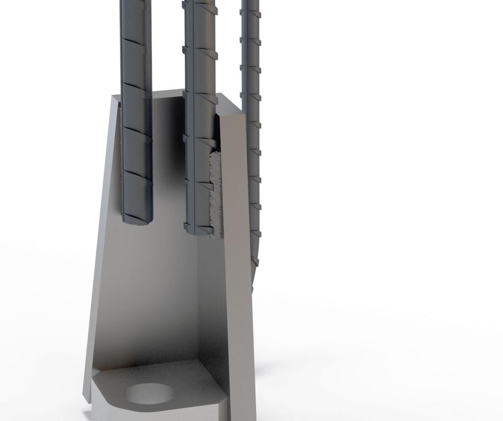
19 Installation of PEC Column Shoe To ensure higher values of concrete cover thicknesses of main anchor bars, in accordance with chapter of the technical manual, follow these instructions for increased values Δ c of concrete cover: Δ c < 5mm, there is no special request for recess boxes; instructions are same as for standard concrete cover of column shoes. The gap is too small to be filled up with concrete. However if the gap is filled or partially filled, the concrete shell can be easily crushed after removing mould. 5 mm Δ c 10mm, self-adhesive foam tape or equivalent can be used to prevent the fill up of the gap. Foam tape of corresponding thickness Δ c is fixed on two sides of the recess box. Δ c > 10mm, to prevent the concrete to fill up the gap, it is recommended to use some kind of solid plate e.g. plywood or hardened polystyrene of corresponding thickness Δ c. These plates can be fixed to the surface of the mould. Use of self-adhesive foam tape to prevent the fill up the gap with concrete. Use of solid plates to prevent the fill up the gap with concrete. Adhesive side of tape Solid plates Ensure of thicker concrete cover by self-adhesive foam tape or solid plates. PEC Column Shoes before and after casting. Version: Peikko Group 09/


20 Installation of PEC Column Shoe Construction site - Assembling the connection Identification of the product PEC Column Shoes are available in standard models (30, 36, 39, 45 and 52) analogous to PPM High-Strength Anchor Bolts M-thread sizes. The model of column shoe can be identified by the name in the label on the product and also according to the color of the product. Color codes are shown in the table hereafter. PEC Column Shoe color identification. Column Shoe Color Code Anchor Bolt Installation Template PEC 30 Black PPM 30 PPL 30 PEC 36 Red PPM 36 PPL 36 PEC 39 Brown PPM 39 PPL 39 PEC 45 Violet PPM 45 PPL 45 PEC 52 White PPM 52 PPL 52 Erection of precast column 1. To level precast concrete column Before erecting the column, upper nuts and washers are removed from anchor bolts. Lower leveling nuts and washers are adjusted at the correct level. The column is erected directly on the pre-leveled washers and nuts. In alternative method shims are placed between anchor bolts and adjusted at the proper level. Lower leveling nuts must be leveled at least 5 mm under the top level of shims to secure that column will rest first on the shims. This method is recommended for heavier columns for easier and faster alignment of the column. 2. To align precast concrete column Upper nuts and washers are screwed on the bolts and column is aligned in the vertical position by leveling nuts. It is practical to use long builder s spirit level, optical or laser level or two theodolites from different directions to ensure verticality. Adequate torque can be achieved typically by impacts of a slog ring spanner (DIN 7444) or open ended slogging spanner (DIN 133) and 1.5 kg sledgehammer. 3. To grout joint and recesses Before loading the column by any other structures e.g. beams or columns, the joint underneath the column and bolt recesses must be grouted by following instructions of the grout supplier. The grout must be non-shrink grade and strength according to plans. To avoid air being trapped in the joint, it is recommended to pour grout from one side of the column only. Grouting formwork is made so that adequate concrete cover for column shoes and anchor bolts is achieved. After grout has reached sufficient strength, the connection is finalized and joining structures may be erected on the column. 20 PEC Column Shoe


21 Installation of PEC Column Shoe Erection of precast concrete column step by step. Column is installed directly on the pre-leveled washers and nuts. Upper nuts and washers are screwed on the bolts. After the nuts are tightened, the crane hook and lifting slings can be released. NOTE! Joint has to be grouted and grout has to reach the designed strength before the column is loaded by other structures. Formwork for grouting joint and recesses. Finalized connection after grouting has hardened. Alternative where grouting is aligned with column face. Filling pipe for grouting Version: Peikko Group 09/
22 Installation of PEC Column Shoe In column to foundation connections wider grouting can be provided to ensure higher concrete cover if it is required. It is recommended to increase the cover in aggressive environment. Installation tolerances and the anchor bolt s protrusion from the surface of concrete when PEC Column Shoes are used. Installation tolerance Top level of foundation Increase of grouting of the column face h b Installation tolerance Grout t g Column Shoe PEC 30 PEC 36 PEC 39 PEC 45 PEC 52 Anchor Bolt PPM 30 PPM 36 PPM 39 PPM 45 PPM 52 Thickness of grouting t g [mm] Protrusion of the bolt h b [mm] Installation tolerance for the bolt [mm] ±3 ±4 ±4 ±4 ±5 22 PEC Column Shoe
23 Technical Manual Revisions Version: PEIKKO GROUP 09/2018. Revision:001* New cover design for 2018 added. Version: Peikko Group 09/
24 Resources DESIGN TOOLS Use our powerful software every day to make your work faster, easier and more reliable. Peikko design tools include design software, 3D components for modeling programs, installation instructions, technical manuals and product approvals of Peikko s products. peikko.com/design-tools TECHNICAL SUPPORT Our technical support teams around the world are available to assist you with all of your questions regarding design, installation etc. peikko.com/technical-support APPROVALS Approvals, certificates and documents related to CE-marking (DoP, DoC) can be found on our websites under each products product page. peikko.com/products EPDS AND MANAGEMENT SYSTEM CERTIFICATES Environmental Product Declarations and management system certificates can be found at the quality section of our websites. peikko.com/qehs