Best Practices for Design and Construction of MSE Walls
|
|
|
- Carmella Bradley
- 5 years ago
- Views:
Transcription
1 Best Practices for Design and Construction Robert A. Gladstone, P.E. Executive Director Association for Mechanically Stabilized Earth Geotechnical Consultant Workshop Ohio Department of Transportation June 7, 2017

2 NOT a Best Geotechnical Practice


3 Common MSE Wall Systems Precast Facing Panels, Steel or Geosynthetic Reinforcements Welded Wire Facings, Steel or Geosynthetic Reinforcements Segmental Blocks, Steel or Geosynthetic Reinforcements
4 Design Roles and Responsibilities Owner Geotech Service Life Requirements Aesthetic Requirements Acceptable Wall Types Global Stability Bearing Capacity Settlement Acceptable Wall Types Civil / Structural Site Grading Wall Location DRAINAGE DESIGN Acceptable Wall Types Loading Internal Stability Detailed facing and reinforcement design Construction drawings MSE Designer
5 Design Responsibility Internal Stability MSE wall system supplier Simple check of sliding and overturning Determine eccentricity and applied bearing pressure Check reinforcement pullout and rupture Design of wall system components External Stability Owner or Consultant Owner proposing to build the structure in the specified location Therefore, owner is responsible for investigating feasibility Includes: global stability, bearing capacity, settlement analysis

6 Global Stability
7 Options for Bearing Capacity and Settlement
8 Specify Requirements in Contract Drawings

9 Contract Specifications
10 Contract Drawings
11 Design Parameters Design usually based on assumed parameters Soil Type Unit Weight Friction Angle Select Granular fill 125 pcf 34 Retained Fill 125 pcf 30 Foundation Soil * * These parameters are actually a good choice: 34 o is maximum value permitted by AASHTO without test data 34 o is approximately the mobilized shear that will develop 34 o has been assumed in design for 4 decades * Foundation soil design parameters should be clearly defined in the contract documents
12 Coherent Gravity Design Reinforced Soil Facing W E Sliding Resistance Vertical Pressure

13 Meyerhof Bearing Pressure Distribution V V = L - 2e e= M C V V V L e = BEARING PRESSURE = SUM OF VERTICAL LOADS = REINFORCING STRIP LENGTH = ECCENTRICITY OF STRUCTURE DUE TO APPLIED LOADS M C = SUM OF MOMENTS ABOUT CENTER LINE DUE TO APPLIED LOADS Best Practices for Design and Construction
14 Characteristics of the Coherent Gravity Method
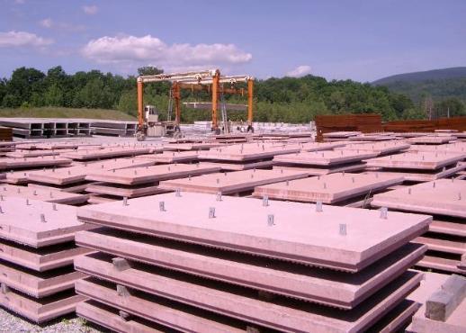
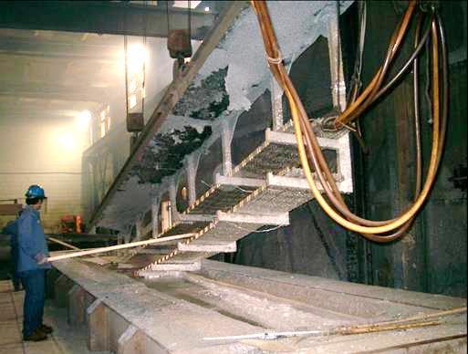
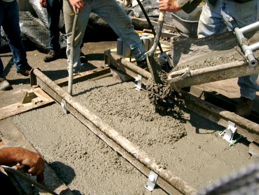
15 Fabrication / QC and QA
16 Attendance Pre-Construction Meeting MSE wall Rep, Resident Engineer, Inspector, Wall Foreman and Crew Presentation by MSE wall Rep Detailed MSE wall construction procedures Compaction of backfill and installation of soil reinforcements Project specific details drainage structures, obstructions, etc Inspection What to look for, what will be required General discussion Discuss what's important to: Resident, Inspector, Contractor
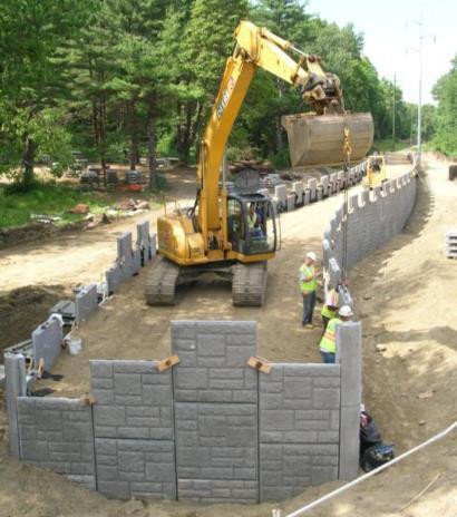
17 MSE Wall Construction
18 Duties of MSE Wall Rep On site for start up of wall construction 2 to 3 Days Instruct on installation of MSE wall components Instruct on backfilling within the MSE wall volume Answer questions of contractor and inspector MSE wall rep is NOT the Inspector The MSE wall Rep is employed by the Contractor


19 Construction Inspection Minimum 95% Standard Proctor Density Required CONSIDER: NHI training course # : Inspection of Mechanically Stabilized Earth Walls and Reinforced Soil Slopes


20 Backfill Selection is Critical Clay backfill = poor friction and drainage Good friction and drainage come from granular backfill


21 Backfill Materials Granular Fill Crushed Stone Expanded Shale LWFC Fill
22 Granular Backfill for MSE Walls Gradation limits per AASHTO U.S. Sieve Size Percent Passing # Some states use different gradation limits and/or reduce fines FHWA allowed up to 25% fines in the early 1980s Backfills often exceeded this limit, up to 35% fines Facing panel alignment was difficult to achieve FHWA and AASHTO returned to 15% limit on fines


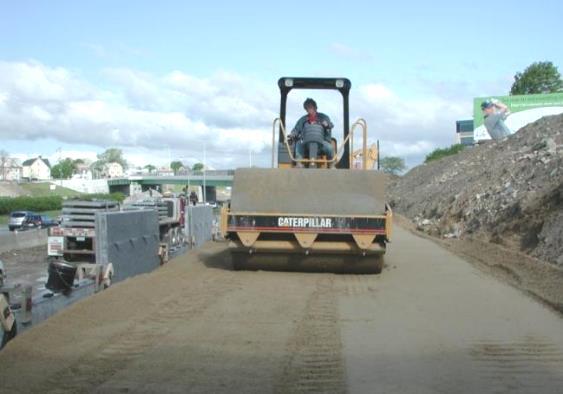
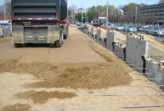
23 Compaction is Important Flat Plate Tamper within 3 ft. of Wall Face Large Roller Stay 3 ft. Away Minimum 95% Standard Proctor Density Required
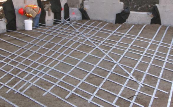
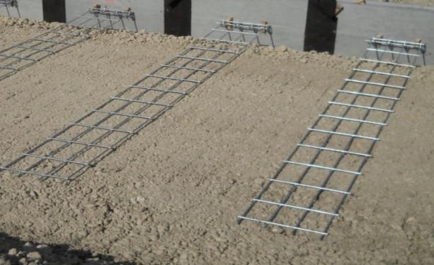
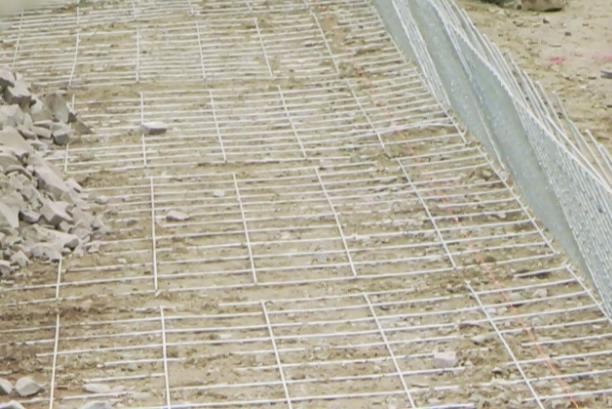
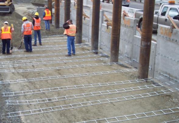
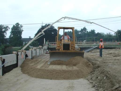
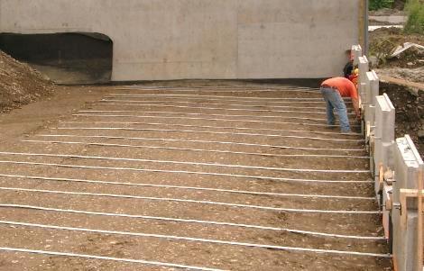
24 Installation of Soil Reinforcements
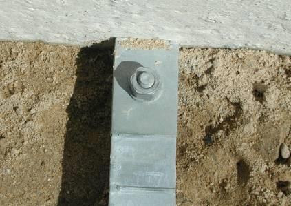
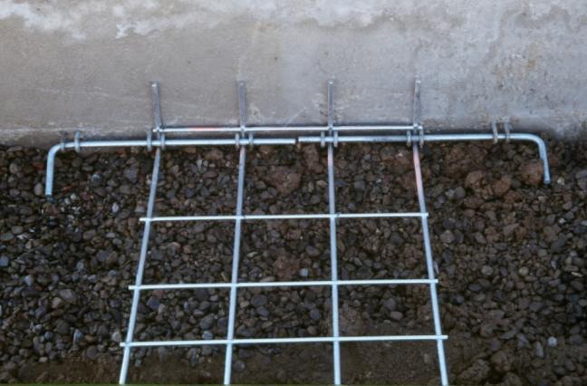
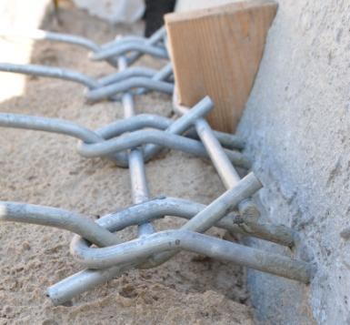
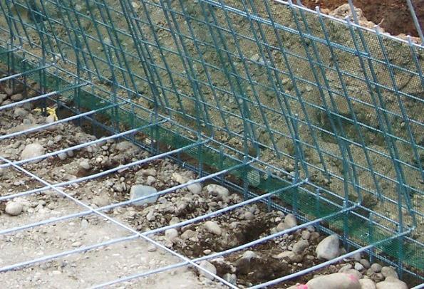
25 Reinforcement Connections are Critical

26 Accommodating Differential Settlement Perpendicular to the Face of Wall 2" Typical for Normal Construction 4" to 6" if expect large settlement Best Practices for Design and Construction

27 Critical Bottom of Wall Details Adequate Foundation Soils Embedment Underdrain

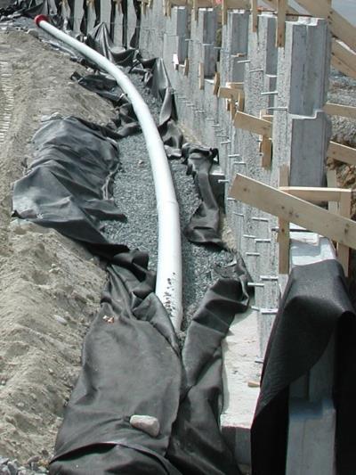
28 Drainage Within MSE Walls
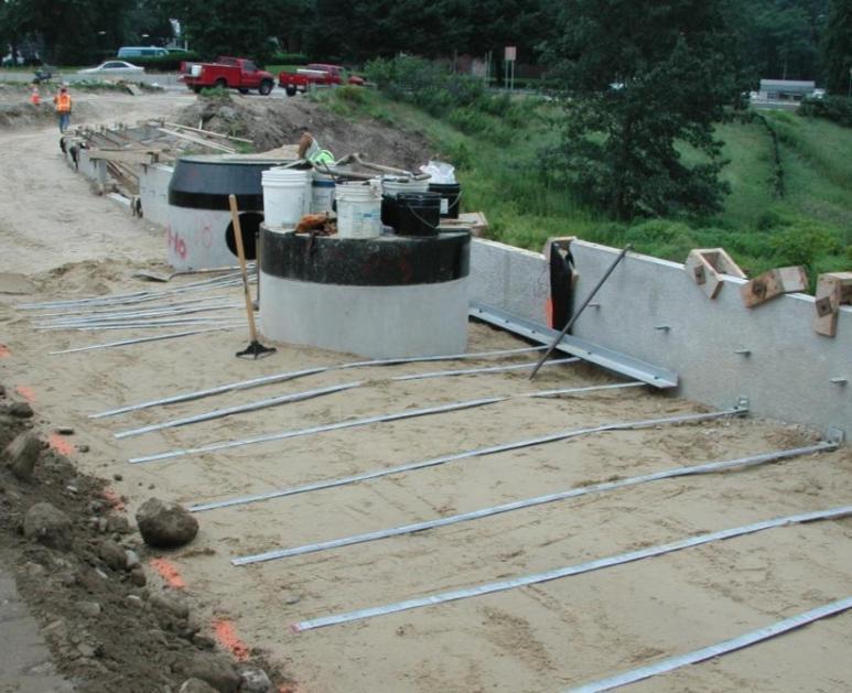
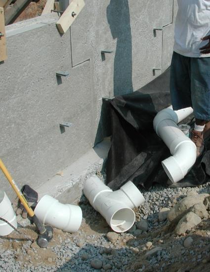
29 Angles Shift Reinforcements at Inlets and Manholes
30 Pipes Behind Walls

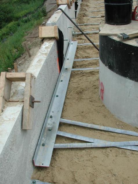
31 Precast Traffic Barrier Design 4-6 Important: Coping Lip Required
32 Membrane with Traffic Barrier


33 Locate Guiderail Posts - Skew Reinforcements
34 Membrane with Guiderail Posts
35 Precast Coping Detail
36 There was a Reason for This! Owner Geotech Service Life Requirements Aesthetic Requirements Acceptable Wall Types Global Stability Bearing Capacity Settlement Acceptable Wall Types Civil / Structural Site Grading Wall Location DRAINAGE DESIGN Acceptable Wall Types Loading Internal Stability Detailed facing and reinforcement design Construction drawings MSE Designer

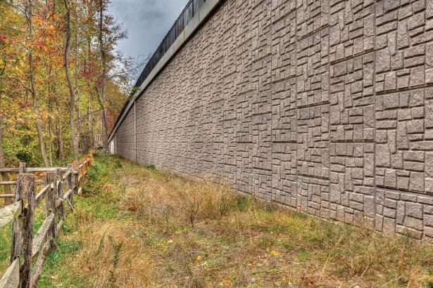
37 That Reason Is Implementing Best Practices Produces Beautiful Long-Performing Structures


")
38 Some of Ohio's Best I-90 Cleveland (2015) In Great Condition! ( yrs) I-75 Dayton (Wright Brothers)


39 Thanks for Listening Front Street City of Berea US 23 & US 30 Interchange Wyandot County Seneca-Jones Road over CSX RR, Seneca County