DYWI Seal Waterproofing System and Bentonite Mats
|
|
|
- Buddy Harrington
- 5 years ago
- Views:
Transcription

1 DYWI Seal Waterproofing System and Bentonite Mats
2 2


3 Contents Introduction... 3 DYWI Seal Waterproofing System... 4 Fields of Application... 4 Main Advantages... 4 System Description... 4 System Components... 5 Technical Features... 5 DYWI Inject SEAL Injection Hose System... 6 Order Information DYWI Inject Accessories... 6 DYWI Seal Bentonite Mats... 7 Fields of Application... 7 Main Advantages... 7 System Description... 7 System Components... 8 Technical Features... 8 Specifications... 9 Technical Data Sodium Bentonite... 9 Installation Procedure Further References Introduction The DYWI Seal Waterproofing System is a needle-punched non-woven impregnated membrane. The membrane structure comprises water absorbing and water swelling polymers. An optional one-side polyethylene film on top of the needle-punched non-woven membrane and the self-healing properties of the DYWI Seal Waterproofing System ensure optimum performance for various water sealing applications. Bentonite mats, also referred to as geosynthetic clay liners (GCL s), are geosynthetic barriers used for various sealing and waterproofing applications in underground mining and civil engineering. DYWI Seal Bentonite Mats are a composite consisting of two layers of geo-textiles filled with sodium bentonite. The application range of DYWI Seal Bentonite Mats comprises waterproofing, gas sealing, and usage as a vapor barrier. Bentonite mats are a proven and versatile sealing system that has been used in many construction projects around the world. 3


 feature")
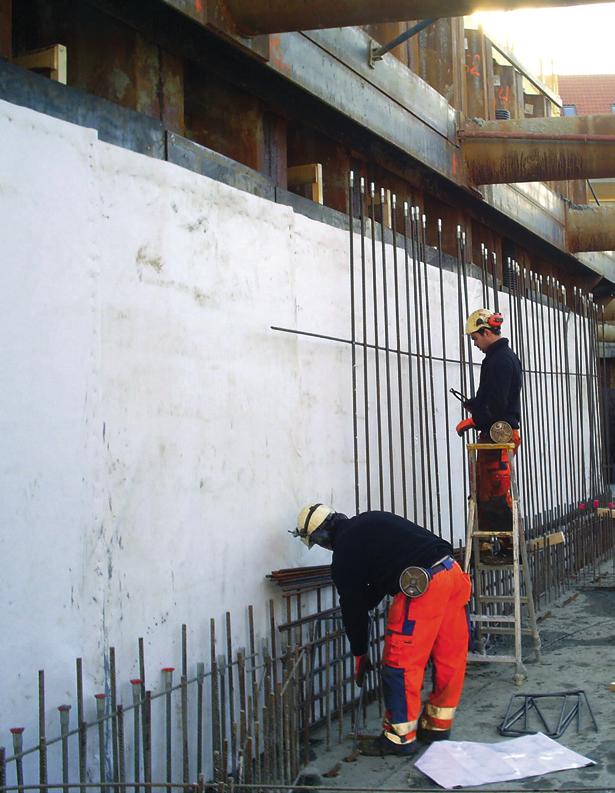
4 DYWI Seal Waterproofing System Fields of Application Protection of structures against ground water Permanent waterproofing of tunnels Water sealing for groundwork operations Waterproofing of excavation pits, dams, or for slope stabilization Application in structural engineering: waterproofing of basements, parking garages, or flat roofs Main Advantages Quick and easy to install Very easy handling on-site due to light-weight design Trouble-free installation even during operation Self-healing properties of the hydrophilic, water reactive polymers Waterproofing safety even when the system is damaged during installation Special welding equipment or specially trained personnel are not required Safe solution for sealing shrinkage cracks and voids in concrete Special formulations for salty water conditions available on request Economic alternative to synthetic liners, bituminous products, and coatings Environmentally sound waterproofing system Innovative sealing technology System Description Penetrating ground water causes an immediate reaction of the swelling polymers - the DYWI Seal Waterproofing System is absolutely watertight SAP (Super Absorbent Polymers) feature optimum swelling capacity Permanent protection against penetrating water Sealing effect up to 2.5 bar water pressure - higher pressure resistance available on request Installation independent of climate conditions and temperatures Overlapping areas are glued to achieve an absolutely watertight effect Tough and resistant High shear strength 4


 Characteristics Unit Value Notes Surface weight [g/m²] > 450 EN 1849-2 Thickness [mm] > 1.")
![5 EN 1849-2, at 20 kpa surcharge Ultimate load, longitudinal (MD) [N/5 cm] > 550 EN 12311-2 Ultimate load, transversal (CD) [N/5 cm] > 1000 EN 12311-2](/docs-images/89/99194213/images/5-3.jpg "Ultimate load strain, longitudinal (MD) [%] > 70 EN 12311-2 Ultimate load strain, transversal (CD) [%] > 55 EN 12311-2 Article No.")
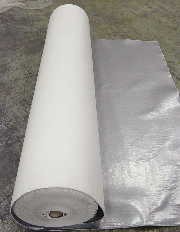
5 DYWI Seal Waterproofing System System Components Swelling, needle-punched non-woven synthetic membrane White polypropylene fibres are fully impregnated with swelling polymers Water absorbing swelling polymers Flexible roll dimensions up to 5 m width - standard version 2 x 50 m DYWI Seal Waterproofing System: synthetic swelling membrane DYWI Seal Waterproofing System with film (silver) - CE label according to EN (ÜZ-5/1195/12, MPA Braunschweig): DSI Waterproofing System Optional one-side UV resistant PE or any other polyolefin or PVC sheathing available Approved injection tubes and accessories are optionally available on request Patented technology Unproblematic waste disposal as standard plastic material Installation procedure: see separate DSI installation manual Technical Features 1) Characteristics Unit Value Notes Surface weight [g/m²] > 450 EN Thickness [mm] > 1.5 EN , at 20 kpa surcharge Ultimate load, longitudinal (MD) [N/5 cm] > 550 EN Ultimate load, transversal (CD) [N/5 cm] > 1000 EN Ultimate load strain, longitudinal (MD) [%] > 70 EN Ultimate load strain, transversal (CD) [%] > 55 EN Article No. [---] ) Specifications only apply to the DSI Waterproofing System 5
 National test certificates Safety data sheet EG No.")

![115 [mm], with high-pressure zerk 809210621113 DYWI Inject Mechanical Packer 17 x 150 [mm], with pan head nipple 809210621517 DYWI Inject Mechanical Packer 19 x 150 [mm], with pan head nipple](/docs-images/89/99194213/images/6-2.jpg "809210621519 DYWI Inject Single-Use Steel Packer 14 x 85 [mm], incl.")
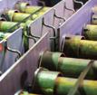
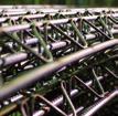
6 DYWI Seal Waterproofing System DYWI Inject SEAL Injection Hose System The DYWI Inject SEAL injection hose system is used for sealing construction joints in combination with the DYWI Seal Waterproofing System. Multiple injection hose system: cement injection Single-use injection hose system: resin injection (DYWI Inject PURE and GELE) National test certificates Safety data sheet EG No. 1907/2006 DSI leaflets on application instructions Order Information DYWI Inject Accessories Article Description Notes Article No. DYWI Inject Mechanical Packer 10 x 70 [mm], with high-pressure zerk DYWI Inject Mechanical Packer 13 x 70 [mm], with high-pressure zerk DYWI Inject Mechanical Packer 13 x 115 [mm], with high-pressure zerk DYWI Inject Mechanical Packer 17 x 150 [mm], with pan head nipple DYWI Inject Mechanical Packer 19 x 150 [mm], with pan head nipple DYWI Inject Single-Use Steel Packer 14 x 85 [mm], incl. Installation wrench DYWI Inject Single-Use Plastic Packer 10 [mm], with cone-head nipple DYWI Inject Single-Use Plastic Packer 18 [mm], with pan head nipple 1/4" DYWI Inject Single-Use Plastic Packer 14 [mm], with pan head nipple 1/4" DYWI Inject Aluminum Adhesive Packer 48 [mm], with cone-head nipple M DYWI Inject Plastic Adhesive Packer 44 [mm], with cone-head nipple M DYWI Inject Plastic Drive Packer 14/18 [mm], with 1/4" threaded connection DYWI Inject SEAL Multiple Injection Hose for cement injection, d. 19 [mm], L = 100 [m] DYWI Inject SEAL Multiple Injection Hose for cement injection, d. 19 [mm], L = [m] DYWI Inject SEAL Multiple Injection Hose for cement injection, d. 11 [mm], L = 100 [m] DYWI Inject SEAL Multiple Injection Hose for cement injection, d. 11 [mm], L = [m] DYWI Inject SEAL Injection Hose for resin injection, d. 11 [mm], L = 50 [m] DYWI Inject SEAL Injection Hose for resin injection, d. 11 [mm], L = 2,500 [m] DYWI Inject SEAL Ventilation Hose Type R, d. 11 [mm], 20 [bar], L = 50 [m] DYWI Inject SEAL Ventilation Hose Type W, d. 11 [mm], 20 [bar], L = 50 [m] DYWI Inject SEAL Shrinking Hose d. 11/19 [mm], L = 50 m L = 30 [m] DYWI Inject SEAL Plug for ventilation hose d. 11 [mm] DYWI Inject SEAL Plug for ventilation hose d. 19 [mm] DYWI Inject SEAL Hose Clamp for injection hose d. 11 [mm] DYWI Inject SEAL Hose Clamp for injection hose d. 19 [mm] DYWI Inject SEAL Shutter Packer for injection hose d. 11 [mm], two-part DYWI Inject SEAL Injection Nipple for two-part shutter packer DYWI Inject SEAL Rubber Plate Type G DYWI Inject SEAL Plastic Connector for hose d. 11 [mm]


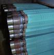
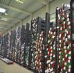
7 DYWI Seal Bentonite Mats Fields of Application Geotechnics and Special Foundations Sealing of storage tanks and reservoirs Base and surface sealing of waste dumps, composting plants, or landfill caps Waterproofing at dams and canals Waterproofing applications around tunnel portals and building sites Mining Temporary sealing of overburden pile foundations Sealing of heap leach pads and slurry ponds Sealing of backfill headings and stopes Permanent waterproofing in the lowest underground mining level Rehabilitation works in abandoned mines Main Advantages Easy handling and application Bentonite sodium granulate features extraordinary swelling potential High long-term shear strength Resistant to chemicals, except saltwater and hydrochloric acid Environmentally sound waterproofing system Long-term field-proven sealing system System Description Mechanically bonded composite, consisting of pulverized or granulated bentonite, embedded and fixed between two layers of geo-textile Flexible installation of DYWI Seal Bentonite Mats, which are simply rolled out Additional sealing of the overlapping area with sodium bentonite powder The sealing layer is covered once installation has been completed Permanent sealing mechanism by single reaction of the sodium bentonite upon water contact 7


8 DYWI Seal Bentonite Mats System Components Woven or non-woven PP carrier layer Granulated or pulverized sodium bentonite filling Non-woven PP cover layer Additional PE membrane cover optionally available Unproblematic waste disposal: standard plastic material Technical Features The main parameters of DYWI Seal Bentonite Mats are their weight, swelling capacity, and the coefficient of permeability Supply of an additional bag of bentonite powder with each roll for application in the overlapping areas Minimum durability of 25 years at a ph value range between 4 and 9 and a temperature of < 25 C Application in combination with DYWI Seal Waterproofing System on request 8
![DYWI Seal Bentonite Mats Specifications 1) Characteristics Unit DS-3500 DS-3700 DS-4000 DS-4500 DS-4700 DS-5000 Remarks Woven PP carrier layer [g/m²] 100 100 100 100 100 100 Sodium bentonite [g/m²]](/docs-images/89/99194213/images/9-0.jpg "3,500 3,700 4,000 4,500 4,700 5,000 Non-woven PP cover layer [g/m²] 200 200 200 200 200 200 Total weight 2) [g/m²] 3,750 4,100 4,250 4,750 5,000 5,300 ASTM D 5993 Dry thickness [mm] 6 6 6,2 6,5 7 7")
![EN ISO 9863-1,2 Index flux [m³/m²/s] 3.2 x 10⁻⁹ 3.2 x 10⁻⁹ 3.0 x 10⁻⁹ 3.0 x 10⁻⁹ 3.0 x 10⁻⁹ 3.0 x 10⁻⁹ ASTM D 5887 Permeability [m/s] 5.0 x 10⁻¹¹ 5.0 x 10⁻¹¹ 5.0 x 10⁻¹¹ 4.0 x 10⁻¹¹ 3.0 x 10⁻¹¹ 1.](/docs-images/89/99194213/images/9-1.jpg "8 x 10-11 ASTM D 5887 Tensile strength, MD 2) [kn/m] 10.4 10.4 10.4 10.4 10.4 10.4 Dry; EN ISO 10319 Tensile strength, CD 2) [kn/m] 8.4 8.")
9 DYWI Seal Bentonite Mats Specifications 1) Characteristics Unit DS-3500 DS-3700 DS-4000 DS-4500 DS-4700 DS-5000 Remarks Woven PP carrier layer [g/m²] Sodium bentonite [g/m²] 3,500 3,700 4,000 4,500 4,700 5,000 Non-woven PP cover layer [g/m²] Total weight 2) [g/m²] 3,750 4,100 4,250 4,750 5,000 5,300 ASTM D 5993 Dry thickness [mm] 6 6 6,2 6,5 7 7 EN ISO ,2 Index flux [m³/m²/s] 3.2 x x x x x x 10-9 ASTM D 5887 Permeability [m/s] 5.0 x x x x x x ASTM D 5887 Tensile strength, MD 2) [kn/m] Dry; EN ISO Tensile strength, CD 2) [kn/m] Dry; EN ISO Ultimate tensile strain [%] EN ISO Grab strength [N] > 400 > 400 > 400 > 400 > 400 > 400 ASTM D 4632 CBR puncture strength 2) [kn] EN ISO Peel strength 2) [N/10 cm] EN ISO Standard roll dimensions [m] 45 x x x x x x 5.1 Length x width Alternative types and dimensions within the indicated range can be provided on request Characteristics Unit Range Woven PP carrier layer [g/m²] Sodium bentonite [g/m²] 100-6,000 Non-woven PP cover layer [g/m²] Optional additional PE membrane cover [g/m²] 180-2,500 Total weight 2) [g/m²] 1,200-6,300 Dry thickness [mm] ) The indicated values are laboratory values and may deviate on-site 2) Characteristic 10% fractile value Technical Data Sodium Bentonite 1) Characteristics Unit Value Remarks Montmorillonite content [%] 80 CUR 33 Moisture Content [%] 12 DIN ,2 Water absorption capacity [%] 650 DIN Swelling Capacity [ml/2 g] 24 ASTM D 5890 Fluid loss [ml] 18 ASTM D ) The indicated values are laboratory values and may deviate on-site 9


10 DYWI Seal Bentonite Mats Installation Procedure 1. Preparation of the foundation basis Removal of sharp rock blocks, organic material, and obstacles that are larger than 50 mm Moisture-free compaction of the ground to a factor of 0.9 of the Proctor density (Proctor compaction test) 2. Installation DYWI Seal Bentonite Mats must be protected from all weather conditions Installation may only be performed in dry surface conditions DYWI Seal Bentonite Mats are rolled out without folds on level ground, which has been previously prepared The woven part faces the ground; in case of one-sided coated mats, the coating faces up Panel must be laid out parallel to slopes and secured accordingly in anchor trenches 3. Overlapping Overlapping of single panels between the two boundary lines printed in the edge area The overlapping area must be increased if major settlements are expected Filling of the overlapping zone with additionally supplied bentonite powder Coverage of DYWI Seal Bentonite Mats immediately after the installation is complete, layer thickness > 25 cm 4. Connection with concrete structures and tube notches See DSI leaflet on the installation of DYWI Seal Bentonite Mats Further References Leaflet on storage and installation of DYWI Seal Bentonite Mats DYWI Inject Systems 10


11 11


12 EMEA DYWIDAG-Systems International GmbH Alfred-Wagner-Strasse Pasching/Linz, Austria Phone Fax alwag@dywidag-systems.at North America DSI Underground Systems Inc S Prosperity Road West Jordan, UT 84081, USA Phone Fax dsiunderground@dsiunderground.com South America DSI Chile Industrial Ltda. Las Encinas #1387, Valle Grande Lampa, Santiago de Chile, Chile Phone Fax informaciones@dywidag-systems.cl APAC/ASEAN DYWIDAG-Systems International Pty. Ltd. 25 Pacific Highway Bennetts Green, NSW 2290, Australia Phone Fax dsi@dywidag.com.au Please note: This brochure serves basic information purposes only. Technical data and information provided herein shall be considered non-binding and may be subject to change without notice. We do not assume any liability for losses or damages attributed to the use of this technical data and any improper use of our products. Should you require further information on particular products, please do not hesitate to contact us. "ALWAG" (AM 952/79), "AT" (AM 6138/2003), "AT-SYSTEM (AM 6139/2003), "DYWI " ( ), "LSC" (AM 4326/2008), "OMEGA-BOLT " ( ), "POWER SET" (AM 6163/2002), and "TUBESPILE" (AM 4328/2008) are registered trademarks of DYWIDAG-Systems International GmbH. "Combi Coat " and "CT-Bolt" are trademarks of Vik Ørsta AS. DYWIDAG-Systems International GmbH is a partner of Vik Ørsta AS. Austria Argentina Australia belgium Bosnia and herzegovina Brazil Canada Chile Colombia Costa Rica Croatia Czech republic Denmark Egypt estonia Finland France Germany Greece GUATEMALA HONDURAS Hong Kong Indonesia Italy Japan Korea Lebanon Luxembourg Malaysia Mexico Netherlands Norway Oman Panama Paraguay Peru POLAND Portugal Qatar Saudi Arabia singapore South Africa Spain Sweden Switzerland Taiwan Thailand Turkey United Arab Emirates United kingdom Uruguay USA Venezuela /12.12-web-he