TOWN OF MIDLAND ENGINEERING DEVELOPMENT DESIGN STANDARDS
|
|
|
- Lindsay Allison
- 5 years ago
- Views:
Transcription

1 Revised December
2 TABLE OF CONTENTS 1.0 DESIGN SUBMISSIONS General Definitions Submissions to Government Agencies Pre-Servicing for Subdivision Development Subdivision Agreement Schedules Administration Fees, Securities, Development Charges First Submission to the Engineering Department Interim Submissions Second and Subsequent Submissions Final Submissions to the Engineering Department Attachments Engineering Drawings Approval of Originals Other Approvals DRAWINGS Specifications for Engineering Drawings:...16 a) Format b) Materials for Final Submission and as-constructed drawings c) Materials for Preliminary Submissions Quality Drawing Sheet Sizes Scales Basic Information Sewer Details Watermain Details Road Details Miscellaneous Details Lot Grading Plan Sanitary and Storm Drainage Plans Engineering Surveys Signs Water GENERAL PLANS General Servicing Plans Storm Drainage Plans Grading Plans Plan-Profile Drawings Erosion and Sediment Control Plans Park Development Trails and Walkways Landscaping As-Constructed Drawings...24 a) Road System b) Storm System c) Sanitary System d) Water System
3 e) Lot Grading ROADWAYS Provincial Standards General Clearing and Grubbing Grading Base Construction Sub-Drains Curb and Gutter Ditches and Culverts Asphalt Special Road Designs Builders Road Driveways Street Name Signs Traffic Signs Pavement Markings Geotechnical Engineering Requirements Inspection - Consultants STORM DRAINAGE SYSTEM General Required System Service Area Minor System Major System Sewers General Stormwater Management...36 a) Stormwater Lot Level Controls b) Stormwater Conveyance Controls c) End-of-pipe Stormwater Controls Stormwater Management Requirements On-Site Stormwater Management Reports Quality Control Hydrologic and Hydraulic Studies Meteorology Sewer Design Hydraulic Design Run-off Calculations Intensity of Rainfall Time of Concentration Pre-Development Post-Development Drainage Area Sewer Material System Layout Storm Sewer Requirements a) Trunk Sewer System b) Pipe Capacities c) Flow Velocities (Flowing full)
4 d) Minimum Sizes e) Depth of Storm Sewers f) Location g) Radius Pipes h) Limits of Construction i) Sewer Alignment j) Changes in Pipe Size k) Standard Easement Requirements l) Testing and Acceptance Maintenance Hole Requirements a) Location and Spacing b) Head Losses and Drops Catchbasin Requirements a) Location and Spacing b) Catchbasins Types c) Catchbasins Leads d) Frame and Grate Roof Leaders, Foundation Drains and Storm Connections Channel, Culvert and Overland Flow Open Channels Open Ditches Watercourse Erosion and Bank Stability Overland Flow Routes Inlet/Outlet Structures Maintenance SANITARY DRAINAGE SYSTEM General Required System Service Area Drains Design Flows Sanitary Sewers Sewer Design System Layout Materials Testing of Sewers and Manholes Service Connections Maintenance Maintenance Holes Limits of Construction SIDEWALKS AND WALKWAYS Sidewalks Walkways Pedestrian Ways Trailways Intersections Boulevards STREET LIGHTING Lighting Levels and Uniformity Ratio
5 8.2 Approval and Construction GRADING AND LANDSCAPING General Overall Grading Plan Tree Planting General Streetscape Standards Notes for Streetscape Submission Drawings List of Details and Specifications Minor Road Street Trees Corner Lot Treatments General Planting Considerations for Internal Streets Standard and Guidelines for Naturalization Areas Notes for Naturalization Submission Drawings Sodding & Seeding Lot Development Plans Fencing EROSION AND SEDIMENT CONTROL General Catchbasin Sediment Control Stone Pad Construction Entrance Construction Access Utilities Canada Post WATER SYSTEM Supply System Source Type of System Reservoir High Lift Pumps and Controls Building Process Piping and Plumbing Electrical Property and Access Water Quality and Treatment Standby Power Operating Manual Distribution System General Service Area Design Flows Selection of Main sizes and Pressures Oversizing Layout Details a) Watermains b) Hydrants c) Valves d) Service Connections e) Restraining Watermain f) Fittings g) Watermain Offsets
6 h) Service Saddles i) Tappings j) Watermain Bedding k) Pipe Deflection l) Protection of Existing Utilities m) Temporary Connection n) Initial Tie-In Swabbing/Charging the Watermain Pressure Testing Chlorinating Flushing Sampling Continuity Test Tie-Ins Maintenance Materials General Watermain Service Connections and Meters Hydrants Valves Specifications Residential Domestic Water Services Design Installation Residential Service Specifications Residential Service Inspections Procedure for Pressure Testing Residential Water Services Water Service Repair Procedure Assumed Subdivision Unassumed Subdivision Residential Water Meters Care of Water Meters Approval of Water Meters Location of Water Meters Remote Wire Installation/Inspection Failure to Register Properly Testing Dispute Test of Water Meters Discontinue the Supply Draining the Plumbing Not For Resale Specifications for General Services, Domestic, and Fire Services Watermain Installation Charges Water Meter Costs Water Service Inspection (Residential Only) Installation/Removal of Hydrant Valve for Testing/Filling Painting Hydrants Operation of Main Valve for Filling Watermain/Service
7 11.21 Fire Protection Charges Plans Approvals MOE Approvals Inspection Contractor s Supervision Liability Insurance Installation and Construction Watermain and Appurtenances Tracer Wire...97 PUBLIC WORKS DEPARTMENT - LOT GRADING GUIDELINES 1.0 LOT DEVELOPMENT PLAN REQUIRED DETAILS Lot Grading - Design Criteria Lot Site Grading Grading Submission Procedure Lot Grading Inspection and Certification Landscaping Implementation Procedures Streetscape Works Naturalization Works Maintenance Agreement for Naturalization Areas Retaining Walls Block Grading Block Grading Criteria Ground Cover PUBLIC WORKS DEPARTMENT - INTERIM GUIDELINES FOR DEVELOPMENTS WITHIN THE LITTLE LAKE WATERSHED 1.0 GENERAL LAND USE PLANNING STORM DRAINAGE SYSTEM Drainage Ditches Infiltration Systems Filter Strips Roof Drain Dry Well STORMWATER MANAGEMENT FACILITY CONSTRUCTION PRACTICES 110 PUBLIC WORKS DEPARTMENT - POLICY MANUAL 1.0 WINTER MAINTENANCE SNOW PLOWING OF STREETS (a) Initial Call-out (b) Priority of Streets: SNOW PLOWING OF SIDEWALKS (a) PLOWING: (b) PRIORITY OF SIDWALKS (c) SIDEWALK SANDING: (d) PLOWED LEVEL ON SIDEWALKS:
8 (e) SNOW REMOVAL ON KING STREET SIDEWALKS: SNOW REMOVAL: SEWER LATERALS INSTALLATION OF NEW SEWER LATERALS: MAINTENANCE OF EXISTING SEWER LATERALS PRIVATE DRIVEWAYS NEW DRIVEWAYS: DRIVEWAY MAINTENANCE: DRIVEWAY RECONSTRUCTION PAYMENT DRIVEWAY CONSTRUCTION BY OWNER: PLANTING, CARE AND REMOVAL OF TREES DEFINITIONS: GOVERNING BODY: PLANTING TREES: CARE OF TREES REMOVAL OF TREES PENALTIES INSTALLATION AND REPAIR OF SERVICES OBJECTIVE: DEFINITIONS: EXCAVATIONS FOR NEW SERVICES: EXCAVATIONS TO REPAIR EXISTING SERVICES: WORK PROCEEDING WITHOUT PERMIT: CUT REPORT SHEETS REQUIRED:
9 1.0 DESIGN SUBMISSIONS 1.1 General 1.2 Definitions Development servicing designs prepared by the Developer s Consulting Engineer are reviewed by the Public Works Department and the Midland Power Utility Corporation with the assistance of the Town Engineering Consultants. The review procedure is set out below. Incomplete submissions which do not attempt to address all aspects of the draft conditions or design standards may be returned with a request to complete the documentation. Standards are to be read in conjunction with the Ontario Provincial Standard. In this specification, the following definitions shall apply: Town shall mean the Town of Midland. Contractor shall mean the firm of Contractors, the company or individual acting as the Contractor and having entered into a contract with the Developer/Owner to install the services. Developer(s)/Owner(s) shall mean the person(s) appearing on the subdivision agreement with the Corporation of the Town of Midland. Town Representative shall mean any person assigned to a project by the Town to carry out work on their behalf. The name of the Representative shall be specified prior to the start of construction on any project. Consultant shall mean professional engineers licensed to practice in Ontario and shall be responsible for the preparation of drawings and specifications to the satisfaction of the Town s Engineering Department. The Consultant shall act on behalf of the Developer/Owner. AWWA shall mean the American Water Works Association. MPUC shall mean the Midland Power Utility Corporation. CSA shall mean the Canadian Standards Association. DFO shall mean the Department of Fisheries, Canada. MNR shall mean the Ontario Ministry of Natural Resources. MOE shall mean the Ontario Ministry of Environment. MTO shall mean the Ontario Ministry of Transportation. 9
10 SSEA shall mean the Severn Sound Environmental Association. OHBDC shall mean the Ontario Highway Bridge Design Code. OPSD shall mean the Ontario Provincial Standards Drawings. OPSS shall mean the Ontario Provincial Standard Specification. 1.3 Submissions to Government Agencies The Consultant shall deal directly with the Ministry of the Environment (MOE), Ministry of Natural Resources (MNR), SSEA, Department of Fisheries and Oceans (DFO) and any other government agencies for works that fall within their jurisdiction. It is the responsibility of the Consultant to ensure that all correspondence, comments and approvals are provided to the Engineering Department. 1.4 Pre-Servicing for Subdivision Development Subsequent to Draft Plan Approval and prior to execution of a Subdivision Agreement, the Town may consider agreeing to pre-servicing of the subdivision at the owner s risk when the following conditions have been met: a) Written acceptance from the Town and the executive Director of MPUC for specific works for which pre-servicing can proceed. b) Engineering drawings have been accepted for construction for the works under consideration. c) Written approval of various agencies, e.g. MOE, NVCA, MNR, MTO, Ministry of Citizenship, Culture and Recreation, where they relate to installation of services permitted by pre-servicing. d) Written confirmation from utility companies including, but not limited to, MPUC, Rogers Cable and Enbridge Gas, that satisfactory agreement has been reached for provision of respective services. e) Upon approval of the pre-servicing application, the Developer must execute and deposit with the Engineering Department, a pre-servicing agreement. f) No permission will be given to construct external services prior to full registration unless a Letter of Credit has been deposited with the Town, for the total cost of the services and all restoration. Connections to existing services will not be permitted until the plan is registered. g) All other documents considered necessary for the works under the Pre-servicing Agreement including 300 mm reserves, easements, etc., must be approved as to form and description. 10
11 h) The engineering and legal fees for the Town must be paid to the Town prior to the commencement of any works. i) Required Insurance Certificate is to be submitted as per the Pre-servicing Agreement. A certified cheque to cover the insurance deductible is to be attached. j) A cash deposit as security for possible emergency maintenance work by the Town is to be submitted as required by the Engineering Department (5% of Schedule E, or a maximum of $10,000). The cash deposit is to be returned at the time of registration of the subdivision. k) Any required rezoning by-laws must be in effect. l) If the underground pre-servicing has been completed prior to the registration of the plan of the subdivision, the Town will not require the full value of the Letter of Credit provided an appropriate reduction request has been submitted and approved by the Engineering Department. m) Above ground works will not be permitted to commence until the execution of the Subdivision Agreement. 1.5 Subdivision Agreement Schedules The following schedules will be required under the Subdivision Agreement: Schedule A Description of Lands affected by this Agreement Schedule B Draft Plan of Subdivision Schedule B-1 List of Drawings Schedule C List of Easements to be granted Schedule D Itemized Estimate Costs of construction for each part of the Public Works to be installed (sample provided overleaf) Schedule E Lots Unsuitable for Building Purposes Schedule F Local Improvement Charges to be commuted Schedule G List of Services to be provided by the Developer and specifications regarding these services. Schedule H Agreement for Special Building Permits Schedule I Sample acceptable Letter of Credit 11
12 Schedule J Lands to be conveyed to the Town Schedule K Declaration of Progress and Completion Schedule L Draft Plan Approval conditions Schedule M Architectural Design Guidelines Schedule N - Copy of Record of Site Conditions as registered with the MOE 1.6 Administration Fees, Securities, Development Charges The administration fees, securities and development charges applicable to subdivision development are stipulated in the subdivision agreement. Reductions in securities will be considered in accordance with the provisions of the subdivision agreement. A sample letter is enclosed overleaf. 1.7 First Submission to the Engineering Department The following documents shall be submitted to the Town Engineer: a. Two sets of drawings and calculations requiring approval. One copy will be returned to the Developer s Consulting Engineer with comments marked in red. b. Two sets of attachments are detailed in Section c. A covering letter to address any previous discussion or submission comments where appropriate. The following submissions shall be compiled and submitted to the Town simultaneously: a. Engineering Submission 1) A Letter of Retainer from the Consulting Engineer stating that they have been engaged for the design and general construction inspection of all works, and coordination of subconsultants. 2) Two complete sets of the following drawings are required: a) Cover Sheet b) Proposed Final Plan for Registration (M-Plan). c) General Plan of Services d) Composite Utility Plan e) Sanitary Sewer Plan (including external drainage plan where applicable) 12
13 f) Storm Sewer Plan (including external drainage plan where applicable) g) Overall Grading Plan h) Tree Preservation Plan i) Plan and Profile drawings of all streets, easements and external works j) Detail sheets including standard and special details k) Other plans as required such as site plan, detention pond plan, etc. 3) A summary of lot area and frontage for each Lot/Block to be developed to confirm by-law compliance prior to registration and Building Department Administration. b. Parks and Landscaping Submission 1.8 Interim Submissions 1) A Letter of Retainer from the Consulting Landscape Architect stating that they have been engaged for the design and complete general construction inspection of all landscape works, plus an outline of the items contained within the submission. 2) A covering letter from the Consulting Engineer (or Consulting Landscape Architect) stating that the landscape work is in conformity with the proposed grading and municipal services for the development, plus an outline of the items contained within the submission. 3) Two copies of the following drawings (where applicable): Existing Natural Features Assessment Tree Survey/Vegetation Analysis and Tree Preservation Plan Streetscape and Buffer Planting Plans Detailed Park Development Plans Stormwater Management Pond Planting Plan 4) One complete set of landscaping cost breakdowns. 5) Two sets of revised landscape drawings as per Town comments. Submit two sets of only the material requiring revisions. 1.9 Second and Subsequent Submissions A covering letter shall be submitted to address any previous comments where appropriate. 13
14 The above procedure shall be repeated as necessary until approval of the engineering drawings and calculations have been received. a) Copies of all other applicable approval agencies comments. b) Two complete sets of all revised drawings, proposed M-Plans and R-Plans. One set will be returned to the Developer s Consulting Engineer. c) Original plus one copy of Ministry of Environment application forms, signed by the Developer and Consulting Engineer. d) Two copies of the Subdivision Agreement Schedules pertaining to Engineering Submission. e) Two copies of Composite Utility Plan f) In addition to storm sewers, sanitary sewers and watermains, MOE approval is required for proposed engineered channels, storm water retention ponds and storm water management features. The Town will not sign the MOE Application until satisfied with the engineering design. It is the Consultant s responsibility to forward the complete application to the MOE Final Submissions to the Engineering Department The following plans and documents shall be compiled and submitted in their entirety by the Consultant in one complete package. Any incomplete submissions, delivered to the Town, shall be returned immediately. 1) One copy of the Proposed M-Plan and R-Plan. 2) Two complete sets of all drawings listed in Schedule B-1 of the Subdivision Agreement 3) Drawing originals (stamped and signed by the Consulting Engineer). 4) A digital copy of the complete set of engineering drawings in accordance with the Town CAD requirements. 5) Two copies of the final storm drainage plan and the storm sewer design sheet labeled final design. 6) Copies of all required approvals, i.e. MOE, etc. 7) Detailed cost breakdown of all proposed works. 8) Two copies of the Owners insurance certificate as per the Subdivision Agreement. 14
15 9) The Developer shall submit evidence, in writing, that agreements are in place with the Bell Telephone Company, Cable TV and Hydro for the allowances within the plan of subdivision Attachments 10) The Developer shall submit evidence, in writing, that agreements are in place with MPUC or any approved Contractor for the installation of street lighting. 11) The Developer shall submit evidence, in writing, that satisfactory arrangements are in place with Canada Post for the location of mailboxes. One set of drawings accepted for construction will be returned to the Consultant. Only drawings accepted for construction shall be utilized during construction of the works. Any changes in drawing originals by the Consulting Engineer are subject to approval by the Town. Upon completion of the construction of the services, the Consultant shall obtain the asconstructed field information and revise the original drawings accordingly. Design submissions are to be accompanied by two copies of any supporting documentation required for the completeness of the design. Such documentation is to include, but may not be limited to, copies of the following reports: a) Soils Report by a Soil Consultant including recommendations for beddings, foundations, groundwater control, retaining walls, slope stabilization, as well as design criteria of the road base materials and surface. If the water table is determined to be excessively high, then the recommendations should include underside of footing elevations and/or provisions for storm sewer connections from weeper tiles. b) Stormwater Management Report addressing methods of accommodating quantity and quality of stormwater run-off and siltation control. c) Traffic Impact Analysis. d) Sanitary and storm sewer calculations on standard design sheets. e) Reference plans for easements being conveyed to the Town Engineering Drawings Engineering drawings shall consist of the following: b) Cover Sheet b) Proposed Final Plan for Registration (M-Plan). l) General Plan of Services m) Composite Utility Plan 15
16 n) Sanitary Sewer Plan (including external drainage plan where applicable) o) Storm Sewer Plan (including external drainage plan where applicable) p) Overall Grading Plan q) Tree Preservation Plan r) Plan and Profile drawings of all streets, easements and external works s) Detail sheets including standard and special details t) Other plans as required such as site plan, detention pond plan, etc Approval of Originals When all outstanding comments have been addressed, the original mylar drawings shall be submitted to the Town Engineer for endorsement by the Town Engineer. Upon return of the endorsed set of originals to the Developer s Engineer, a set of mylar copies shall be forwarded to the Director of Public Works Other Approvals 2.0 DRAWINGS A copy of all other approvals including all requisite draft plan condition approvals, which may be required for the development, shall be submitted to the Town Engineer. This may include, but not be limited to, the approvals received from the following authorities: Ministry of the Environment, Ministry of Transportation, Ministry of Natural Resources, etc. 2.1 Specifications for Engineering Drawings: a) Format Autodesk, AutoCAD, Dwg format Minimum version R14, unless otherwise approved. b) Materials for Final Submission and as-constructed drawings Bond for final submissions Translucent mylar for as-constructed drawings (.04 mm matte) Black ink (permanent) Digital copies on CD c) Materials for Preliminary Submissions Bond Black ink (permanent) 16
17 2.2 Quality All original drawings and prints shall be neat, legible, and in ink using Leroy lettering system or equivalent quality and shall be corrected for as-constructed in the same manner. All information shall be neat, legible and original sheets shall be typed or completed in ink and reproducible by a white-printing or photocopy machine. The purpose of this section is to outline the minimum design requirements for the construction of municipal services in the Town of Midland. These requirements are general in nature and do not relieve the Developer of the responsibility for submitting a completed product demonstrating competent engineering design in full compliance with all applicable legislation 2.3 Drawing Sheet Sizes 2.4 Scales Drawings shall be a consistent size of 594 mm by 841 mm (metric size A1). Standard metric scales to be used are 1:20, 1:25, 1:50, 1:100, and their factors of 10. Scales shall be as follows and shown on the drawings: 2.5 Basic Information the key plan shall be shown on the cover sheet at a scale of 1:5000; the General Service Plan and the Sanitary and Storm Sewer Plans shall be 1:1000. The following standards shall apply in preparation of the drawings: All plans shall include a north arrow in the upper right quadrant. All east-west streets shall generally be drawn with the north arrow pointing to the top, all northsouth streets with the north arrow generally pointing to the right, and all cul-de-sacs or other roads where this does not apply shall be drawn with the stations numbered from left to right. All elevated data shall be referred to geodetic datum and at least one bench mark shall be shown on each plan indicating a proposed elevation; The intersection of centrelines of streets shall be used as zero chainage. The centreline chainage is to be shown in ink from the outset, calculated from the final survey. When the plan must be broken because of curvature, etc., the profile shall be broken as well, so that insofar as possible, chainage points in plan and profile will coincide vertically; 17
18 In general, east-west streets shall have zero chainage at their westerly limits and north-south streets shall have zero chainage at their southerly limits. Chainages on a plan-profile shall increase from left to right. All existing utilities, structures and other features such as trees and hedges shall be shown and identified using a broken line. All services to be constructed are to be shown in solid lines; The beginnings and ends of curves must be shown on a plan and profile with the radius of curvature shown on the plan. Chainages of points of curvature shall be calculated from the final plan. The chainage elevations and names of intersecting streets shall be shown in plan and profile; The drawings shall be in ink at the outset, according to the final survey. Street names shall be kept clear of the road allowance; The drawings shall show any required off-street drainage and separate profiles should be prepared for drainage easements. The drawings shall show clearly the proposed profiles, road widths and crosssections, ditches, ditch gradients, curb and gutter gradients, culvert sizes, gauges and gradients, existing and proposed services, and limits of the proposed work. All detail for intersecting streets, including grades, must be shown for a minimum distance of 30 metres from the intersection of the intersecting street. All street lines shall be shown and all easements for drainage or services. Larger scale detail may be required for congested bends and/or cul-de-sacs. The drawings shall show the lot frontage distances and dimensions of the easements and land to be dedicated to the Town. The Town Engineering Consultants shall be consulted as to the manner of showing information not set out in these requirements. 2.6 Sewer Details The standard abbreviations, sewer diameter, length grade, manholes, inlets and connections to the sewer shall be shown on appropriate General Plans. This information plus sewer bedding, type and class of sewer pipe, manhole numbers and inverts, flow direction, grate elevations and drop structures shall be shown on Plan and Profile Drawings. Chainage of manhole locations shall be shown in profile. Service locations to be shown on plan drawing. 2.7 Watermain Details The standard abbreviations, watermain diameter, length, type and class of pipe, and the valves, services, hydrants and connections to the watermain shall be shown on appropriate General Plans and on Plan and Profile Drawings. 18
19 2.8 Road Details Horizontal control data (beginning and end of curve, radius, length, etc.) shall be shown on appropriate General Plans and on Plan and Profile Drawings. Vertical control data (proposed road grade, length of run and percent slope, beginning and end of vertical curves) shall be shown on Lot Grading Plans and on Plan and Profile Drawings. Existing and proposed centreline road grades shall be shown every 20 metres with stations shown measured in metres with kilometres separated by a + sign on long runs (e.g. STA , STA , STA STA ). Stations of interest (curve stations, intersections, end stations, etc.) shall be shown calculated to the nearest millimetre (e.g. BVC STA , EVA STA , END STA ). 2.9 Miscellaneous Details Other details shall be according to the Town s Standard Drawings where applicable or if a Town Standard Drawing is not available, in accordance with Ontario Provincial Standards. Town Standards take precedence when available. All necessary details shall be included on sheets similar to other drawing sheets, if not on relevant drawings. Town Standard Drawings may be printed on these sheets directly Lot Grading Plan see Town of Midland Lot Grading Policy Manual 2.11 Sanitary and Storm Drainage Plans scales 1:500 to 1:2000 or as approved by the Director of Engineering R.O.W. s easements roads, curb and gutter, ditches, sewers, maintenance holes, catch basins, watermains, connections, sidewalks, walkways, street lights, lots and blocks with numbers, street names, existing and proposed profile at center line of road top, sewer and watermain grades, class of pipe, size, bedding, existing utilities etc Engineering Surveys 2.13 Signs All engineering surveys must be tied into the Ontario Horizontal Control Survey Network (Cosine) in accordance with Ontario specifications and guidelines and regulations under The Surveys Act (OS 79). In that regard, plans shall be provided in an AutoCad compatible, digital form and referred to Horizontal Control Survey UTM (Zone 17) NAD 83. Project Identification Signs Unassumed Roads Signs 19
20 2.14 Water Design Criteria Submission of Plans and Approvals Inspection By-laws and Agreements Installation and Construction Residential Water Services Industrial/Commercial Townhouse Projects Developed under Site Plan Material Data Sheets * See Town of Midland Water Specifications Section 3.0 GENERAL PLANS 3.1 General Servicing Plans General plans showing above-ground services and appurtenances are to be drawn to a scale of 1 to 1000 and shall indicate, but not be limited to, the following: roadways and street names; watermains and appurtenances, with notes showing sizes; maintenance hole numbers; sewers with notes showing sizes and direction of flow; lot numbers per registered plan with provision to add street addresses when available; school signs; street signs; future land use signs; barricades; fencing; retaining walls; rear lot/block catchbasins; easements including dimensions and descriptions; driveway location for corner lots; bus stop platforms; community mail boxes; hydro vaults, street lights, sidewalks. 20
21 3.2 Storm Drainage Plans Storm drainage plans are to be drawn to a scale of 1 to 1000 (a scale not exceeding 1 to 5000 will be accepted for large external drainage areas) and are to indicate the total area to be drained by the proposed storm sewers. The storm drainage plan is to be compatible with the grading plan and the Town s latest contour mapping. The storm drainage plan shall indicate, but not be limited to, the following: existing contours; drainage patterns of adjacent lands; run-off coefficients and areas (ha) of tributary areas outside the development and for each section of the storm sewers within the development; direction of run-off; street names; maintenance hole numbers; sewer sizes, slope and directions of flow; any catchbasins or swales, on the lots or blocks, required to collect the run-off; temporary or permanent quantity and quality storm water management facilities; major and minor overland flow routes; culverts and other drainage appurtenances. 3.3 Grading Plans Grading plans are to be drawn to a scale of 1 to 500 or larger showing existing contours established from a topographic survey of pre-development conditions. The grading plans shall indicate, but not be limited to, the following: existing contours extended outside the subject lands far enough to determine the existing drainage pattern; driveway locations and building envelopes; centre line elevations of existing roads at 20m intervals; elevations of existing trees, structures, watercourses, etc.; proposed elevations of roads at 20m intervals; proposed elevations at front and rear of building envelope; proposed elevations at the corners of each lot and block; proposed elevations side yard highpoints, if applicable; proposed 0.5.m contours for grading within large blocks and parks; proposed grades for major and minor overland flow routes; lot fabric of subject lands including lot, block and easement description; physical structures such as fencing, retaining walls, etc.; proposed grades for storm system to intercept block and external drainage 21
22 3.4 Plan-Profile Drawings Plan-profile drawings are to be drawn to a horizontal scale of 1:500 and a vertical scale of 1:50 and are to conform to the following: where multiple drawings are required for one street, match lines must be used and there shall be no overlap or duplication of information; where intersecting streets or easements are shown on a plan-profile, only the diameter of the pipe and direction of flow of the intersecting sewers shall be shown; on profile portion of drawings the type of sewer, diameter, length, grade and class of pipe shall be shown; on profile portion of drawings the watermain diameter, length and class of pipe shall be shown; only the type and diameter of pipe shall be shown in the plan portion; where possibility of conflict with other services exist, connections are to be plotted on the profile or a crossings chart included; pavement/road base designs for the particular roadway are to be indicated on all plan-profile drawings; the detail information from all borehole logs is to be plotted on the profile drawings and located on the plan; gutter drainage details for turning radii, cul-de-sacs and intersections. 3.5 Erosion and Sediment Control Plans Erosion and sediment control plans are to be prepared in accordance with Provincial Standards. 3.6 Park Development Detailed Park Development Plans are to be submitted by the Consulting Landscape Architect. A complete set of detailed design plans and working drawings are required. Park plans are to be submitted at a scale of 1:500 and shall indicate, but not limited to, the following: existing contours; drainage structures and direction of overland drainage; species and size of existing plant material to remain and be protected; species and size of plant material to be removed; layout of all proposed recreation facilities; layout of parking lot and spaces (including handicapped parking); proposed site amenities including benches, bike racks, trash receptacles, signs; perimeter fencing; park lighting; all surface treatments; all proposed plant materials. 22
23 A Park Development Cost Estimate based on estimated quantities with corresponding unit prices is required. The Developer s responsibility for park development includes rough grading topsoiling (min 150mm), and hydro seeding and installation of perimeter fencing according to Town s standards. 3.7 Trails and Walkways 3.8 Landscaping The Developer may be required to design and construct a trail system, pathways and linkages to existing trail systems. Trail development will be implemented according to Town of Midland Trail Standards. Pathways will be required adjacent to parkland and walkway easements adjoining parallel roads or acting as service access shall be fenced, gated and planted according to Town standards. The provision of new trails shall be consistent and support the existing Town-wide trails network. Trails extending the existing Canada Trails network shall be 4.57 meters wide concrete trail per town details. Proposed trails should link together local points of interest, all open space amenities, civic institutions and connect to the Canada Trails network. To the extent possible, the route should be off-road, utilizing public open spaces, right-of-ways and easements. Trails connecting through urban areas located within the road right-of-way should be paved multi-purpose cycle ways. Trails through sensitive natural features should be designed as soft surface paths and located to avoid fragile areas. Entrance points to the trail system should be marked with signage co-ordinated with the Town. All landscape plans shall be drawn and stamped by a full member of the Ontario Association of Landscape Architects. All landscape plans shall be drawn at a minimum scale of 1:500. The landscape documents may include the following drawings: existing natural features assessment; tree survey/vegetation analysis; tree preservation plan and details; streetscape and buffer planting plans and details; detailed park development plans and details; trails master plans and details; landscape restoration plans and details; stormwater management pond planting plan. Detailed cost estimates will be required for all approved landscape plans. This estimate will be used for security purposes. All streetscape plans shall be consistent with the Town of 23
24 Midland Subdivision Design Guidelines and will require Town approval before implementation of the plans. The streetscape plan shall show the following: all existing trees and natural features to remain; all building envelopes, driveways and sidewalks; all walkways, trails and easements; all required fencing including privacy, acoustic and chain link; all proposed plantings; all entry features; location of street lighting; location of public utility boxes and easements and hydrants. Construction details will be required for all landscape elements to be implemented as part of the development. All required landscape Restoration Plans and Stormwater Management Facility Planting Plans will require the Town of Midland s approval prior to implementation of the plans. Developers are required to display approved landscape plans at the sales pavilions for the homebuilders in the new subdivision. 3.9 As-Constructed Drawings a) Road System Before the expiration of the maintenance period for both underground and above-ground services, two sets of as-constructed drawings are to be forwarded to the Town Engineer for review and comments. Revisions must have been made to the drawings to reflect any changes to the line and/or grade of the roadways and services, and to incorporate all the grading modifications resulting from final lot grading. All manholes, catchbasins, valves, hydrants, curb stops and service connections shall be properly tied into fixed reference points. If any revisions are required, one set of red-lined drawings will be returned to the Developer s Engineer. When all revisions and/or corrections have been made, a complete set of as-constructed mylars shall be submitted to the Director of Public Works. A copy of the drawings on the computer CD shall also be submitted. The drawings shall be sealed and signed by a Registered Professional Engineer and stamped as-constructed and dated. The Town performs a spot check of elevations and locations. The as-constructed drawings shall include the following information: 1. Elevation of centre line of roadway every 20 metres. 24
25 b) Storm System c) Sanitary System 2. Revised horizontal and vertical curve information. 3. Any additional information that has been required for construction after approval of engineering drawings. 4. Revised benchmarks located in a permanent location throughout the new development at sufficient intervals such as on fire hydrants and/or other permanent structures. In addition, the following shall be indicated on the as-constructed drawings: driveways, lay-byes, curb depressions; road signage; laneway marking and stop bar locations. 1. Invert elevations of all storm sewers. 2. Invert elevations of all storm manholes. 3. Revised percentage of all storm sewers along with as-constructed distances between manholes. 4. Any additional information that has been required for construction after approval of engineering drawings. In addition the following shall be indicated on the as-constructed drawings: pipe/culvert size, grade, type, class/gauge, bedding; chainage from MH along main to service tees. 1. Invert elevations of all sanitary sewers. 2. Invert elevations of all sanitary manholes. 3. Revised percentages of all sanitary sewers along with as-constructed distance between manholes. 4. Locations measurements to all sanitary service connections to each individual lot. These should have swing ties from property corners or other fixed structures such as fire hydrants and manholes. 5. Any additional information that has been required for construction after approval of the engineering drawing. 25
26 In addition, the following shall be indicated on the as-constructed drawings: pipe size, grade, type, class, bedding; chainage from MH along main to service tees; dimensions from lot corners and elevations for service laterals. d) Water System 1. Elevations of top of watermains every 20 metres. 2. Location measurements to all water service boxes for each individual lot. These should have swing ties from property corners, buildings or other fixed structures such as fire hydrants and manholes. 3. Location by measurement of tees, bends, valves, and dead ends. 4. Any additional information that has been required for construction after approval of the engineering drawings. 5. Obvert elevations at 30m intervals. 6. Chainage from appurtenances along main-to-main stops. 7. Dimensions from lot corners and elevations for service laterals. e) Lot Grading 4.0 ROADWAYS 4.1 Provincial Standards 1. Elevations of the final lot grades for all lot corners for the entire plan of subdivision. 2. Invert elevations of all culverts. 3. Invert elevations of all ditches at 20 metre intervals. MTO, Geometric Design Standards shall apply together with these Town Standards. Where there are any apparent conflicts or discrepancies the Town Design Standards and Standard Drawings shall take precedence. 26
27 4.2 General 8.0 m minimum pavement width plus curb and gutter each side (except industrial Roads on 26.0 m wide right-of way which may be 8.0 m minimum pavement Width on 12.0 m wide granular base including 2.0 m granular shoulders and sodded ditches) center line radius horizontal curves per MTO Geometric Design Standards m minimum radius to property line from center line for residential cul-de-sacs 21.0 m minimum radius to property line from center line for industrial/commercial Cul-de-sacs minimum grade = 0.5%, maximum grade change = 1% in 6 m, with a minimum Road cross fall of 3%, maximum grade to be no greater than 7%, 3% maximum cross fall in cul-de-sacs The following are general requirements for the design of right-of-ways and roads: All roads to be constructed in the Town of Midland shall be designed to urban standards unless specific approval from the Town is received prior to the development plan receiving draft plan approval. Roads designed to rural standards will only be considered for estate residential or industrial developments or for developments within the Little Lake Watershed. Where the development adjoins or incorporates an existing Highway, County Road or Town arterial road as shown on the Town s Official Plan, the Developer shall deed to the Ministry of Transportation of Ontario, County or Town the required widenings and/or daylighting. Minimum horizontal curve centerline radius shall be 14.5 for all cul-de-sacs and crescents. Minimum horizontal curve centerline radius for all other roadways shall be in accordance with MTO Geometric Standards. Minimum K-Valves for all roadways shall be in accordance with MTO Geometric Standards. In all cases, the K-Valves for crests and sags shall be no less than 8 and 4 respectively. Vertical curves are required for a change in grade greater than 1%. The minimum grade for all roadways shall be 0.5%. The maximum grade shall be 8% for local residential roadways and 6% for all other roadways. Minimum right-of-way width shall be as follows: Residential -Local Urban -Local Rural 20.0 m 26.0 m 27
28 -Major Collector 26.0 m Industrial -Local -Collector Arterial 20.0 m 26.0 m 30.0 m Minimum pavement width shall be as follows: Residential -Local -Local Rural -Major Collector 8.0 m 6.6 m 11.0 m Industrial -Local & Collector 7.5 m Arterial 14.0 m The edge of the roadway paved surface shall have a minimum radius at intersections of 8 m for residential roads and 18 m for industrial roads. Finished roadways shall have a crossfall of 3 percent from the centerline to each outside curb line. On all streets, horizontal and vertical sight distances conforming to MTO geometric design standards shall be provided. Cul-de-sac turning circles shall have a minimum radius of 21.0 m to property and 15.0 m for asphalt. The road design for industrial and/or commercial developments shall take into account the type of traffic anticipated on the development. Granular base thicknesses, asphalt type and thickness, shoulder width, cul-de-sac radii shall be designed specifically for the development utilizing these standards as minimum requirements. Where new roads are to connect to existing roads the design shall extend along the existing road for a sufficient length to verify a satisfactory transition. All roads are to be extended to the limit of the subdivision boundary and shall terminate at a cul-de-sac when not connecting to an existing road unless otherwise approved by the Town Engineer. Roads shall be classified as arterial, collector or local in accordance with the Town Official Plan. Provisions shall be included in the road design for communal (super) mailboxes. The developer will be responsible for providing parking areas, structural concrete 28
29 foundations, electrical supply etc. all as required by the Town, in locations designated by the Town. Private internal roadways shall conform to OPSD Clearing and Grubbing 4.4 Grading It is the Town s policy to preserve trees wherever possible. Therefore, trees shall be removed from the Road Allowance only to obtain proper sight distances, grading, ditching etc. All stumps, logs, brush, boulders, debris etc. shall be removed from the development site and deposited in a disposal area approved by the Town and all other affected authorities. The boulevard area from the curb to the property line shall be graded to provide positive drainage toward the roadway if possible, minimum 2% grade. For roads having an approved rural design section (i.e. estate residential or industrial) the area between the edge of the road shoulder and the street line shall be graded and the ditches cut with maximum slopes of 3 m horizontal to 1 m vertical from the edge of the shoulder to the bottom of the ditch and from the bottom of the ditch to the original ground. In fills over 1.5 m measured vertically from the edge of shoulder to the toe of slope shall not be steeper than 3:1. The ditch shall be located at the toe of the fill slope. All shoulders, side slopes, ditches and boulevards to the streetline shall be protected with a minimum 150 mm of topsoil and nursery sod. Rip-rap (150 mm size minimum) over filter fabric shall be provided in areas requiring erosion control and as required by the Director of Public Works. 4.5 Base Construction 4.6 Sub-Drains The sub-grade shall be shaped to conform to the required grade and shall have a cross fall of 3% from the centerline of roadway to each side. The native sub-grade shall be compacted to a minimum of 98% SPD and shall be proof rolled. No granular base shall be placed until the grade on which it is to be laid has been inspected and approved by the Director of Public Works. For roadways with curb and gutter, sub drains shall be provided on both sides of the road base for the purpose of draining the granular road to a suitable outlet. The sub-drains shall be installed for the complete length of roadway unless the recommendations of the soils report specify a shorter length. However, in no case shall the length of the sub-drains be less than 15 m on each side of all catchbasins. The sub-drains shall consist of 150 mm diameter CSP piping with a filter fabric rap. 29
30 4.7 Curb and Gutter Single stage curb and gutter shall conform to OPSD Two stage curb and gutter shall conform to OPSD Materials shall be in accordance in OPSS. Single stage curb and gutter may be installed after the placement of base asphalt and granulars, provided that prior to the placement of curb and gutter, the limit of the base asphalt extends a minimum of 1.0 m beyond the proposed face of curb and that a machine laid asphalt gutter is provided. 4.8 Ditches and Culverts all ditches are to be protected from erosion and restored with 100 mm top soil and staked sod or other erosion protection method as directed entrance culverts to be a minimum 450 mm in diameter (1.6 mm CSP gauge) road crossing culverts to be minimum 600 mm in diameter (2.0 mm CSP gauge) all culverts to be supplied with headwall end protection constructed of flag stone, interlocking wall systems and/or concrete or other materials as approved by the Town of Midland, to a maximum elevation that is flush with the top surface of the driveway 4.9 Asphalt As soon as the granular base has been completed, it shall be thoroughly compacted and shaped and the base course asphalt placed. The base course shall consist of 50 mm minimum thickness of HL8 Base Course Asphalt, or as recommended by Geotechnical Engineer. The surface course Asphalt shall not be placed for at least two years from the date of placement of the base course asphalt and until 70 percent of the houses have been constructed, which ever is greater. The surface course shall consist of 40 mm minimum thickness of HL3 Surface Course Asphalt. All asphalt materials and work shall conform in all respects to OPSS. Testing will be carried out as required by the Director of Public Works. The above depths of asphalt are minimums and the actual depth may increase to reflect the requirements of the Pavement Design Soil Report and/or local conditions if deemed necessary by the Director of Public Works. Base course asphalt shall be O.P.S.S. HL8. with a minimum insitu A.C. content of 4.5%; Industrial subdivisions will require specific pavement design included in the soils report. Tests of subgrade materials must be conducted by a recognized soils laboratory and be acceptable to the Town. Copies of tests, along with proposed road designs, shall be submitted 30
31 to the Town. Minimum thickness of asphalt and granular material shall be as indicated on Town Standard Drawings in all cases Special Road Designs Special road designs, which are not covered by Town of Midland Standards, shall be in accordance with the most recent provisions of the geometric design standards manual and urban street geometrics, as adopted by the Municipal Engineers Association. (i.e. Special Design will be required in high density residential, commercial and industrial areas) Builders Road 4.12 Driveways A road will be classified as a builders road when the granular bases and sub-drains, first stage curb and gutter, base course asphalt and rough grading of the boulevards has been certified complete by the Developer s Engineer and accepted by the Director of Public Works. O.P.S.S. Granular A and Granular B materials are most commonly used for road construction in the Town of Midland. The Town will consider crushed products with the following provisions: - where roadways which contain four or more paved lanes, the curb lane roadway pavement specification shall be increased as follows: - the binder course (base) asphalt under the bus route or curb lane must be increased by 50 mm; - on four lane roadways and bus routes, the base course asphalt shall be HDBC (OPSS 1149). Driveways to be a minimum of 50 mm HL3A on a minimum of 200 mm of Granular A for Residential and 75 mm HL3A on a minimum of 250 mm of Granular A for Commercial/Industrial or alternative equivalent surface material as approved by the Director of Public Works (paving stone, concrete) Minimum concrete strength: 30 MPa at 28 day test All driveways shall be paved from road edge to minimum property line Minimum grade: 0.5% Minimum radius to edge of pavement at cul-de-sacs: 15.0 m residential, 17.0 m industrial/commercial Curb sections may be no closer than 1.5m from the edge of the street pavement Height of the curb shall be no more than 150mm above the finished pavement Curb to be depressed at intersection for sidewalks (i.e. Wheel Chair Ramps, per OPSD) 31
32 Concrete curb and gutter to be continuous through all entrances Driveway section to be 4.0 m at single driveways and 6.0 at double driveways, width of triple driveways to satisfy zoning by-law requirements (not more than 50% of lot frontage) Rural driveways shall include an entrance culvert unless the driveway is at a ditch highpoint. Unless warranted by specific conditions the pipe size for a new culvert installation shall be a minimum 400mm diameter dimension, in either aluminized corrugated steel or double walled smooth interior high density polyethylene (HDPE) pipe The maximum length of culvert is 18.0 metres All rural driveways require an entrance approval permit. The maximum grade for access driveways shall be 7% unless otherwise approved by the Town Engineer. This maximum grade is not recommended and should be employed only in exceptional cases where conditions prohibit the use of lesser grades. The minimum grades permissible are 2% on boulevards and 1% on lots. Maximum grade change shall be in accordance or OPS All access driveways shall be located a minimum of 1.5 m from light poles, hydro transformers, catchbasins, hydrants, watermain valves, Bell manholes, Bell and Cable T.V. junction boxes, water service valve boxes, side lot lines and other driveways. All access driveways shall also be located a minimum of 10 m from the street lines for corner lots. Where frontage limitations interfere with standard locations site specific solutions shall be detailed with the Plan and Profile and Lot Grading Plans Headwalls shall be constructed to protect the driveways from erosion and underpinning at the culvert edge. Head walls may be constructed of formed concrete or masonry laid and secured in place 4.13 Street Name Signs Street name signs shall be supplied and erected by the Developer. Street name signs shall be double sided 160mm extruded aluminum with length to suit lettering. Lettering shall be black on a white retro-reflective background. Signs shall be mounted on 73mm diameter galvanized steel post imbedded at least 1.2 metres into the ground. Mounting hardware shall be extruded aluminum post caps, crossmounting bracket or end bracket, installed in accordance with manufacturer s recommendation. Street name signs shall be installed at all intersections within the development Traffic Signs 32
33 Traffic control signs shall be supplied and erected by the Developer as directed by the Director of Public Works. Signs shall be in compliance with the Ontario Traffic Manual (OTM) Regulatory Signs and shall be placed in accordance with the OTM and the Highway Traffic Act. All traffic control signs are to be made with high intensity type reflective sheeting (a minimum sheeting level of Type III or IV must be used for Stop signs and appurtenances and Yield signs and appurtenances). Where warranted, the Director of Public Works may require Warning Signs. Unless other directed, posts shall be galvanized steel U-Flange type imbedded at least 1.2 metres into the ground with length to suit the application Pavement Markings Upon completion of the final asphalt paving and upon notification by the Town, the surface of the roadway shall be painted in conformity with the standards of the Ministry of Transportation Ontario at all intersections, school crossings, walkways and railway crossings to clearly indicate the proper traffic zones and stop lines Geotechnical Engineering Requirements At the preconstruction meeting, the General and Geotechnical Consultant are required to provide the Town with a Schedule of the works, together with the names of all inspectors to be on site during the construction of the various phases of the works. The General Consultant must have their own site representative on site during any grading and/or construction works. The Geotechnical Consultant must ensure that OPSS regarding backfilling and compaction within road allowances and lots where fill exceeds 1.0 m in thickness is strictly adhered to. The Geotechnical Consultant s certification must make reference to this specification Inspection - Consultants In new developments, the owner shall engage a Geotechnical Engineering Consultant to prepare a report on the existing soil conditions which is to include: 1) The identification, description and limits of the existing soil regimes, including the extent of topsoil and its suitability for reuse. 2) The suitability of native materials for trench backfill. 3) The conditions under which the native material may be used as trench backfill. 4) The procedures to be used for high moisture contents and water table levels which may affect the proposed servicing or structural works of the concerned area and surrounding lands. 33
34 5) The extent of native material which is unsuitable for trench backfill and the procedure for dealing with is such that it will not affect the structural stability of the proposed municipal services. 6) Areas and procedures to be followed where blasting may be required with due consideration to surrounding structures and services. 7) The road material depths for pavement design. 8) Any special recommendation for bedding materials. 9) Potential corrosive or chemical problems that may affect services or structures (e.g. high sulphates) and the method of resolving such problems. 10) Recommendations in dealing with filling conditions within the road allowances, on building lands, in the construction of berms etc. 11) Identify problem areas and recommend mitigating procedures regarding the stability of existing slopes and the extent of unstable soils or conditions. 12) Any special recommendations to be followed in the design and construction of building foundations. 13) The engineering properties of the native material including frost susceptibility, natural moisture content, compaction characteristics, relative density and structural integrity. 14) Recommendations in achieving proper compaction. 15) Recommendations in dealing with deep excavation of trenches. 16) Recommendations in dealing with septic or well systems that may be affected by the proposed building and servicing works. 17) The report is to confirm that sufficient boreholes have been taken to establish definite requirements and recommendations for the servicing and building works. General Soils Report must identify minimum bearing capacity of the native soil (i.e. 75 kpa) preferably on a hole by hole basis. Boreholes located in the area of proposed underground municipal services are to be taken to a depth of at least one (1) meter below the deepest trench. 18) Requirements and recommendations contained within this report along with borehole logs and grain size analysis of the native soils are to be incorporated by the engineering consultant into his first submission to the Town Engineer. Any such requirements and recommendations that are not so incorporated are to be drawn to the Town s attention with specific reasons. 19) During construction, the owner is to retain a geotechnical consultant to supervise the installation of bedding and the backfilling of all trenches within road allowances and easements. A trench backfill certification is required to indicate that sufficient tests have 34
35 been carried out to obtain a representative report as to the compaction of the backfill and they find the backfill to be in compliance with Town Specifications and requirements. 20) A final subgrade certification is to confirm that the final subgrade conditions are equal to or better than those anticipated in the preparation of the pavement design. If these conditions are less than what was anticipated, the owner and the Town are to be immediately advised with a new pavement design recommendation. This certification has been made to the best of the Geotechnical Consultant s knowledge and information. This certification however, does not relieve the Contractor, the Owner or any other parties of their respective responsibilities pertaining to maintenance or otherwise. * Where grading operations require the placement of engineered fill the Geotechnical Engineer must certify that the fill located at 1.0 m below finished grade and deeper has been sufficiently compacted to assure a minimum bearing capacity of 75 kpa and 98% Standard Proctor Density. NOTE: The material testing of any major structure, as determined by the Town, is to be carried out by an independent testing firm. Such testing is to be carried out in accordance with the latest revision of the O.P.S.S. and C.S.A. requirements. All test results are to be forwarded to the owner, the engineering consultant, and the Town, with the appropriate comments and recommendations. Upon completion of the material testing, the testing firm is to certify to the owner and the Town that the material requirements for the concerned structure have been achieved. 5.0 STORM DRAINAGE SYSTEM 5.1 General Required System Service Area Generally storm drainage shall be accommodated by a system of curb, gutter and storm sewers in all subdivisions except industrial or rural subdivisions of subdivisions within Little Lake Watershed for which open ditch drainage may be permitted if minimum design criteria can be realized. The storm drainage system is to be designed to limit flood damage and hazards under long term storm conditions, to provide a reasonable level of convenience and safety for pedestrian and traffic use by removal of lot and street surface runoff under short term storm conditions and to prevent the impairment of water quality and disturbance to natural streams. The system shall be designed to service all areas within the subdivision to their maximum future development in accordance with the Official Plan. Allowance shall be made for inflows from the appropriate adjacent storm sewers, subdivisions or areas. Discharge of the system is to be to the appropriate adjacent sewer or watercourse. The exact location for connecting sewers or channels to adjacent sewers or areas shall be approved by the Town Engineer. 35
36 5.1.3 Minor System Storm Sewers shall be designed for at least a 5 year return frequency storm without surcharge and are to be sized using the Rational Method. Relevant figures are to be entered on Storm Sewer Design Sheets Major System The combination of overland flow system and minor system shall be designed for the 100 year return frequency storm Sewers General minimum drop across maintenance holes = 30 mm for straight runs, 75 mm for >0 degrees to 45 degrees deflections and 150 mm for 45 degrees to 90 degrees deflection minimum cover = 1.5 m frost protection from obvert of pipe minimum vertical and horizontal pipe separation between sewer and watermain to conform to Ministry of the Environment criteria structural design checks shall be carried out to ensure that the combined live and dead loading does not exceed the three edge crack bearing strength of reinforced concrete pipe or exceed 5% maximum vertical deflection in the case of PVC pipe the minimum grade for the furthest upstream storm manhole run must be not less than 1.0% 5.2 STORMWATER MANAGEMENT A hierarchy of preferred stormwater management practices is outlined in the M.O.E Stormwater Management Practices Planning and Design Manual. It consists of (i) Stormwater Lot Level Controls, (ii) Stormwater Conveyance Controls and (iii) End-of-pipe Stormwater Controls. a) Stormwater Lot Level Controls Stormwater lot level controls involve treating stormwater before it reaches the development conveyance systems. The following are different types of lot level controls available: - Reduced Lot Grading - Rear Lot Ponding - Soakaway Pits 36
37 b) Stormwater Conveyance Controls Stormwater conveyance controls are implemented as par of the conveyance system. Stormwater conveyance controls can be categorized into four types of systems: - Pervious Pipe Systems - Pervious catchbasins - Grassed Swales - Open Ditches c) End-of-pipe Stormwater Controls End-of-pipe stormwater controls receive stormwater from a conveyance system and discharge the treated water to receiving waters. The various types of end-of-pipe systems are as follows: - Wet Ponds - Dry Ponds - Constructed/Artificial Wetlands - Infiltration Trench - Infiltration basin - Filter Strip - Sand Filter - Oil/Grit Separator Stormwater Management Requirements The stormwater management requirements generally must reflect district solutions and vary depending upon the watershed, and in some cases the storm sewer shed, that the site is located. Site specific requirements can be obtained from the Town. A stormwater management report will be required for all development applications On-Site Stormwater Management Reports A Stormwater Management Report setting out the existing and proposed drainage System shall be submitted for approval to the Director of Public Works. The report must also be submitted for approval to the Ministries of the Environment and Natural Resources and address the following points: the modified rational method, or equivalent, is to be used for the analysis; a control device (orifice) must have a diameter of no less than 75 mm in order Prevent clogging of the opening; control devices shall be installed on the upstream side of the maintenance hole; storm connections from the building roof and foundation drains must be made downstream of the maintenance hole and/or catchbasin inlet controls; ponding limits and available storage are to be depicted on the site servicing drawings, and the maximum ponding depth in parking areas is not to exceed 250 mm; an overland flow route shall be clearly marked on drawings. The grading of parking lots and landscaped areas must provide a safe path for the overland flow route to the surrounding municipal right of way during storms exceeding the design storm event; 37
38 roof drains should be selected to give a minimum discharge of cms/ha of roof area; details and concepts are to conform to the Urban Drainage Design Guidelines, set out by the MOE; all on-site storm water management requires a Certificate of Approval from the MOE under the Transfer Review program. Two completed MOE Application forms are to be submitted to the Town; where applicable, approval will be required from NVCA; a Professional Engineer must approve and stamp the on-site storm water management report and site servicing drawings; on-site storm water management applications are to be accompanied with four folded site servicing drawings and four on-site storm water management reports Quality Control Potential increases in runoff rates resulting from new development shall be controlled as required by the Town. Typical methods of quality control are temporary storage of water on parking lots, discharging rainwater leaders onto grassed areas and downstream stormwater retention ponds. Where downstream constraints exist such as those established by the Town or the Ministry of Natural Resources, the drainage report shall demonstrate how runoff rates will be controlled to satisfy those constraints. In the absence of such constraints, the post-development flows from the 5 year return frequency storm generally shall not exceed the flows for pre-development conditions for the same storm at the outlet for the minor system unless it is demonstrated to the satisfaction of the Town Engineer that uncontrolled flows will have no adverse effects. Similarly for the major system, post-development runoff from 25 year and 100 year return frequency storm generally shall not exceed the pre-development runoff for the same storm. Quality control facilities shall be provided to the satisfaction of the Town Engineer, the Ministry of the Environment and the Ministry of Natural Resources. Stormwater quality controls are to be implemented on all applications in accordance with the applicable master drainage or subwatershed plan or site specific stormwater management plan. The Town of Midland requires MOE Level 1 quality control on all sites Hydrologic and Hydraulic Studies When required, hydrologic studies shall employ an appropriate modeling technique with defensible parameter values. The study shall describe the modeling parameters and the criteria for their selection as well as input and output data. The consultant is to assume full responsibility for the proper application of the hydrologic models. The Town recommends that the Consultant follow the MTO Drainage Management Technical Guidelines. To facilitate municipal review, the following documentation must be submitted. 1) Map showing the modeling subcatchments. 2) Summary tables that provide the following data on each modeling subcatchment: 38
39 * total drainage area; * pre and post-development impervious area; * pre and post-development runoff coefficient to each ground cover element (rooftop, street, grass, etc.); * total drainage area devoted to each hydrologic soil group; * storage volumes associated with pre and post-developed runoff control measures Meteorology 3) Map showing the drainage areas with modeling parameters, proposed facilities and pre and post-development flows at all crossings. The intensity-duration frequency (IDF) curves used for the Town of Midland were originally derived from rainfall data taken from the Orillia Atmospheric Environment services weather station. The equations for these curves are as follows: 2 Year Storm 1= (T.C ) Year Storm 1= (T.C ) Year Storm 1= 1387 (T.C ) Year Storm 1= (T.C. +8.3) Year Storm 1= (T.C ) Year Storm 1= (T.C ) Based on these IDF curves, the Consultant is to develop the proper design storms for use in hydrologic studies. In general, the SCS design storms should be used for determining the hydrographs for undeveloped watersheds and for checking detention storages required for quantity control. The Chicago design storms should be used for determining hydrographs in urban areas and also for checking detention storage. In many cases, the consultant will be required to run both sets of design storms to make sure that the more stringent is used for each individual element of the drainage system (pipe flow, street flow, channel flow, detention storage). 39
40 The time step for discretization of the designed storm can vary according to the size of the sub-watershed, but must not exceed the estimated time of concentration. The maximum rainfall intensity should be compatible with that of real storms on record. 5.3 SEWER DESIGN Hydraulic Design Sewers shall be a minimum of 300 millimetres in diameter. Mannings Formula shall be used to calculate required pipe sizes. The roughness coefficient for smooth bore pipes shall be The minimum velocity shall be obtained by selecting a slope to ensure that cleansing velocities occur once in two years on the average. Generally 0.75 metres per second for the 5 year return storm design flows may be used. The first leg shall have a minimum of 1.00%. All other legs shall have a minimum grade of 0.50%. The normal maximum velocity shall be 5.00 metres per second at full flow for sewers and 1.50 metres per second for channels. Energy dissipaters at outlets will be designed to reduce velocities to 1.00 metre per second or less. A sufficient drop shall be provided across each manhole to offset any hydraulic losses, the obverts of inlet pipes shall not be lower than obverts of outlet pipes, and drop structures shall be used only when drops of more than 0.9 metres are necessary. Calculations for hydraulic losses shall be included with storm design information. The minimum drop across manholes shall be 30 mm for straight runs, 75 mm for 0 degrees to 45 degree deflections and 150 mm for 45 degree and 90 degree deflections. Except for special cases, the downstream pipe diameter shall always be greater than or equal to the upstream pipe diameter Run-off Calculations Flow Calculation Rainfall equations or curves and design storm hydrographs must be approved by the Director of Public Works. When the Rational Method is used, an initial inlet time of 15 minutes shall be used except where the zoning requires the use of a coefficient of 0.6 m or higher in which case a 10 minute inlet time shall be used. 40
41 Run-off coefficients are to be determined from the most recent MOE Guidelines. A minimum run-off coefficient of 0.55 is to be used for undeveloped upstream area where future residential development is expected and 0.75, where future industrial, high-density residential or commercial development is expected. Run-off coefficients for the Rational Method shall be as follows: Lawns: Sandy soil, flat, 2% Sandy soil, average, 2-7% Sandy soil, steep, 7% Heavy soil, flat, 2% Heavy soil, average, 2-7% Heavy soil, steep, 7% Business: Downtown Areas Neighborhood Areas Residential: Single-Family Areas Multi Units, Detached Multi Units, Attached Suburban Apartment Dwelling Areas Industrial: Light Areas Heavy Areas Parks, Cemeteries Playgrounds Railroad Yard Areas Unimproved Areas Streets: Asphalt Concrete Brick Drives and Walks Roofs
42 Storm sewers shall be designed to drain all lands based on the Rational Method. The Rational Method calculations must be checked using a model approved by the Town Engineer where the drainage area is greater than10 hectares. The larger of the flows is to be used in the design of the sewer system unless approved otherwise. Q= C I A where: Q = Flow in cubic metres per second A = Area in Hectares C = Run-off coefficient I = Intensity in mm/hr Intensity of Rainfall The intensity of rainfall is to be determined from the Intensity-Duration-Frequency values from the Atmospheric Environment Services Orillia Station Time of Concentration The minimum initial time of concentration is to be 15 minutes Pre-Development To calculate the initial time of concentration (tic) for upstream, undeveloped lands, the following formula may be used: Bransby Williams, HYMO/OTTHYMO, SCS Upland Method, etc. The most appropriate method will be determined at the discretion of the Town Post-Development To calculate the initial external time of concentration (tc) for external lands that are scheduled for future development, a straight line is to be drawn from the furthest point within the watershed to the proposed inlet. The top 50 metres shall have an initial tc of 10 minutes and the remainder shall have tc assuming the velocity in the sewer is 2m/s. The summation of the two tc s will give the future external time of concentration. If the upstream area has adequate storm sewers, channels, or culverts, the velocity of the flow through these sewers, channels, or culverts shall supersede the 2m/s calculation Drainage Area Drainage systems must be designed to accommodate all upstream drainage areas considering interim and ultimate conditions Sewer Material Pipes for main sewers shall be concrete or PVC DR35 with a minimum diameter of 300 mm and shall conform to CSA Standard A257.1 with a minimum strength of 65D Class III or as required by depth. 42
43 Pipe for catchbasin leads shall be concrete with a minimum strength of E.S. or PVC DR28 rubber gasket type joints with a diameter of 250 mm for singles and 300 mm for doubles. Sewers shall be constructed with bedding as per OPSD , Class B-1, Granular A unless otherwise directed by the Town Engineer. Catchbasin frames and grates shall be as per OPSD and shall be as manufactured by McCoy (or approved equivalent). 5.4 SYSTEM LAYOUT Roof leaders are to be discharged to the ground surface to splash blocks and flows are to be directed away from the building in such a way as to prevent ponding or seepage into weeping tile. Where flat roofs are used, as in commercial or industrial sites, detention roof hoppers requiring smaller or fewer roof leaders cannot be used as part of the stormwater management design. Weeper tiles are not to be directly connected to the storm sewer system unless permission is received from the Director of Public Works. All other connections to the storm sewers shall be made as approved by the Director of Public Works. Storm sewers shall generally be located as per the standard detail drawing for storm sewer. At bends in the road allowance the storm sewer shall follow along the same side. When storm sewers or open drainage channels are located on easements the easement width shall be 4.0 minimum. This minimum must be increased where the depth or diameter of service dictates greater working room. A minimum depth of 1.5 metres to the spring line from the finished road or ground surface elevation, or a sufficient depth for any foundation drains or other connections shall be provided. Fill beneath sewers is to be compacted to 98% SPD. Minimum clearances between services shall be provided in accordance with MOE guidelines. Manholes shall be placed at the end of each sewer, at changes in size and material and at changes in grade and alignment. Curved or properly deflected sewer lines may be allowed with the approval of the Director of Public Works. Manhole tops are to be set to base course asphalt grade and then adjusted to final grade, when top lift of asphalt is placed. The maximum spacing between manholes shall generally be according to the following: Metres to 750 mm dia
44 - 825 to 1200 mm Over 1200 dia. 155 Deflection of storm sewers at a manhole shall not be more than 90 degrees. Drop manholes shall be provided for all sewer junctions having an elevation difference in excess of 0.9 metres that cannot be eliminated by changing sewer grades. Where manholes are located in areas to be flooded by the major storm design and surcharged sewer design is not used, manhole covers shall be of the sealed variety. Where manholes are located where the surcharged sewer design hydraulic grade line is higher than the rim elevation, manhole covers shall be of the bolted variety. In all other areas standard manhole covers shall be used. Catchbasins are to be located at all low points, upstream of pedestrian crossings and not within 1.0 m of curb depressions. Preferable, catchbasins where required will be adjacent to lot lines. The maximum allowable spacing shall be 80 m where catchbasins are not used as inlet controls. Where catchbasins are designed for inlet controls, spacing shall be determined by design. Catchbasin leads shall be minimum 250 mm at a minimum grade of 0.7% for single catchbasins and 300 mm at a minimum grade of 0.7% for double catchbasins. Leads shall connect to manholes where possible. Where catchbasins are designed for inlet controls, lead sizes down to 150 mm for singles or doubles can be used where such sizes will limit flows to the gravity capacity of the sewer system. Rear lot catchbasins shall be located 1.5 m from the back lot line and 1.0 m from the side lot line and the catchbasin and lead shall be located in a minimum 4.0 m wide easement centered on the lot line Storm Sewer Requirements a. Trunk Sewer System b. Pipe Capacities A trunk sewer system shall be defined as part of a drainage system that drains an area of 100 ha of land or greater. Trunk storm sewer systems shall be designed to accommodate a 25 year storm. Manning s formula shall be used in determining the capacity of all storm sewers. The capacity of the sewer shall be determined on the basis of the pipe flowing full. The value of the roughness coefficient n used in the Manning s formula shall be as follows: - concrete Pipe concrete box culverts corrugated Metal 68 x 13 mm corrugations
45 - corrugated Metal 25% paved invert PVC Pipe c. Flow Velocities (Flowing full) d. Minimum Sizes For circular pipes the minimum acceptable velocity is 0.75 m/s and the maximum acceptable velocity is 4.0 m/s The minimum size for an on street storm sewer shall be 300 mm. e. Depth of Storm Sewers f. Location g. Radius Pipes Storm sewers shall have a minimum frost cover of 1.5 m. Where the minimum cover is not possible the Engineer shall provide a design solution with consideration for additional loading due to frost. The storm sewers shall be located as shown on the standard Town of Midland road cross section drawings. A minimum clearance of 500 mm shall be provided between the obvert of the sanitary sewer and the invert of the storm sewer. The sanitary sewer connections are required to go under the storm sewer. Radius pipe shall be allowed for storm sewers 975 mm in diameter and larger provided that a maintenance hole is located at the beginning or at the end of the radial section. The minimum center line radius allowable shall be in accordance with the minimum radii table as provided by the manufacturers. h. Limits of Construction Sewers shall be terminated with a maintenance hole at the subdivision limits when external drainage areas are considered in the design. The design of the terminal maintenance holes must allow for the future extension of the sewer. i. Sewer Alignment Storm sewers shall be laid in a straight line between maintenance holes unless radius pipe has been designed. Joint burial (common trenching) with sanitary sewers will be considered when supported by the recommendations of a soils report prepared by a qualified Geotechnical Engineering Consultant. 45
46 j. Changes in Pipe Size No decrease of pipe size from a larger upstream to a smaller size downstream will be allowed regardless of the increase in grade. k. Standard Easement Requirements The minimum width of easements for storm sewers shall be in accordance with the following guidelines. Size of Pipe Depth of Invert Minimum Width of Easement 250 to 375mm 3.0 m maximum 4.0 m 450 to 675mm 3.0 m maximum 4.5 m 750 to 1500mm 3.0 m maximum 6.0 m 1650mm and up 4.0 m maximum 4.0 plus 3 times O.D. of Pipe For easements containing more than one pipe or underground service the minimum width will be based on the above chart for the maximum pipe size plus 3.0 m. Regardless of the preceding, all situations will be reviewed and judged on individual cases at the discretion of the Town. In areas where it is difficult to control the infiltration of ground water into the sewer trenches a clear stone may be used provided it is completely wrapped in a suitable geotextile, selected and installed in accordance with the manufacturer s requirement. The width of trench at the top of the pipe must be carefully controlled to ensure that the maximum trench width is not exceeded unless additional bedding or higher strength pipe is utilized. l. Testing and Acceptance All storm works shall be thoroughly flushed and/or cleaned of debris and all pipes shall have a CCTV inspection as per OPSS 409 as part of the final acceptance inspections Maintenance Hole Requirements Maintenance holes may be either precast or poured in place and shall be designed and constructed in accordance with the most recent OPSS and OPSD. Where the standard drawings are not applicable, the maintenance holes shall be individually designed and detailed. a. Location and Spacing Maintenance holes shall be located at each change in alignment, grade or pipe material, at all pipe junctions, at the beginning or end of radius pipe sections and at intervals along the pipe to permit entry from maintenance to the sewer. 46
47 Maximum spacing of maintenance holes shall be 300 to 750 mm in diameters. for 110 metres and 825 to 1200 mm in diameter for 125 metres and anything over 1200 diameters for 155 metres. The change in direction of flow in any maintenance hole shall not be more than 90 degrees. Maintenance holes shall be located, wherever possible, a minimum of 1.5 m away from the face of curb and/or any other service. b. Head Losses and Drops Suitable drops shall be provided across maintenance holes to compensate for the loss in energy due to the change in flow velocity and for the difference in the depth of flow in the sewers. In order to reduce the amount of drop required, the designer shall, wherever possible, restrict the change in velocity between the inlet and outlet pipes to 0.6 m/s. Hydraulic calculations shall be submitted for junction and transition maintenance holes on sewers where the outlet is 1050 mm diameter of greater. In addition, hydraulic calculations may be required for maintenance holes where the outlet pipe is less than 1050 mm diameter if, in the opinion of the Town, there is insufficient invert drop provided across any maintenance hole. Regardless of the invert drop across a maintenance hole as required by calculations, the obvert of the outlet pipe shall not be higher than the obvert of the inlet pipe at any maintenance hole location. The minimum drops across maintenance holes shall be as follows: Change of Direction Minimum Drop (mm) 0 degrees 30 1 degree to 45 degree degree to 90 degree Catchbasin Requirements Catchbasins must be precast and shall be designed and constructed in accordance with the most recent OPSD and OPSS requirements. a. Location and Spacing Catchbasins shall be selected, located and spaced in accordance with the conditions of design. The design of the catchbasin location and type shall take into consideration the lot areas, the lot grades, pavement widths, road grades and intersection locations. 47
48 Maximum spacing for catchbasins including cul-de-sac gutters shall be as follows: - Road grade 0.5% to 0.75% - 70 m - Road grade 0.76% to 3.0% - 95 m - Road grade 3.1% to 4.5% - 90 m - Road grade greater than 4.6% - 75 m Catchbasins shall be generally located upstream of pedestrian crossings. Catchbasins shall not be located in driveway curb depressions. b. Catchbasins Types Typical details for single, double, and rear lot type catchbasins are shown in the OPSD. Any special catchbasins and inlet structures must be fully designed and detailed by the Engineer for approval by the Town. Double catchbasins are to be installed at the low point of any road. c. Catchbasins Leads For single catchbasins the minimum size of connection shall be 250 mm and the minimum grade shall be 2.0%. For double catchbasins, including rear lot catchbasins, the minimum size of connection shall be 300 mm and the minimum grade shall be 2.0%. Doubles with back arches to be provided in sags. In general, catchbasins located in close proximity to a downstream maintenance hole shall have their leads connected to the maintenance hole. Long catchbasin connections (in excess of 20 m) shall be connected to a maintenance hole. d. Frame and Grate The frame and cover for catchbasins in roadway or walkway areas shall be as detailed in the OPSD , with type B open cover. Catchbasins located within the traveled portion of a roadway shall have the frame elevation set flush with the surface of the base course asphalt. The adjustment and setting of the frame and cover shall be completed in accordance with the details provided in the OPSD Catchbasins located in grassed areas shall have the Birdcage Grate per Roof Leaders, Foundation Drains and Storm Connections Roof leaders shall not be connected directly to the Town sewer systems. Leaders shall discharge to concrete splash pads in landscaped areas and directed to side yard swales. Foundation Drains 48
49 It is the Town policy that foundation drains shall not be connected directly to the Town sewer systems. A sump pump system shall discharge to a concrete splash pad in a landscaped area and with the water directed to side yard swales. The geotechnical report shall consider the ground water table elevation and recommend minimum basement elevations. Foundation drain discharge water that becomes a nuisance shall be corrected Channel, Culvert and Overland Flow For channel, culvert, bridge and/or erosion control projects the proponent is responsible for obtaining all necessary approvals from the governing agencies, such as the MNR, DFO and/or MOE. Culverts and Bridges Road Classification Arterial Collector Urban Local Rural Local Temporary Detour Driveway Design Flood Frequency 1:100 Year to Regional 1:50 Year 1:25 Year 1:25 Year 1:10 Year 1:5 Year Bridges and other major drainage structures shall require special designs as determined by the Town. Hydraulic calculations will be required. The frequency and magnitude of flooding or erosion shall not be increased on upstream or downstream properties. 5.5 OPEN CHANNELS The proposed criteria for an open channel design shall be submitted to the Town for approval prior to the actual design being undertaken. Open channels shall be defined as major system overland flow channels, minor system outfall channels or natural channels. Major system overland flow channel designs may be required to accommodate the Regional storm or the 100-year storm for new development. Natural channel design criteria will be determined on a site by site basis. The following guidelines must be considered: Open Channels Minimum Velocity Maximum Velocity Grass lined Natural 0.7 m/s 1.5 m/s Grass lined Maintained 0.7 m/s 1.5 m/s Gabion lined 0.7 m/s 2.5 m/s Concrete lined 0.7 m/s 4.0 m/s 5.6 OPEN DITCHES 49
50 In industrial developments, rural developments or developments within the Little Lake Watershed open ditches may be permitted by the Town. Ditches shall be constructed below the sub-grade of the roadway a maximum of 0.5 m and a minimum of 0.15 m. The minimum ditch grade shall be 0.5% and the maximum 6%. In exceptional cases and where ditches are on easements off the Road Allowance, ditches with grades greater than 6% may be allowed by the Director of Public Works but these shall be suitably protected against erosion to the satisfaction of the Engineers. The minimum ditch protection on all ditches shall be 150 m of topsoil and staked sod on the side slopes and bottom of the ditch regardless of the ditch gradient. Normal ditch to ditch road culverts shall be installed where required as follows: - Minimum Length; as required from centre of ditch to centre of ditch; - Minimum size; 500 mm diameter for road crossing, 400 mm driveway; - Material; standard galvanized corrugated pipe, spirally corrugated pipe will not be permitted; - Gauge; as recommended by manufacturer for H20 Highway loading, minimum 2.0 mm thickness; - Cover; 300 mm minimum for road crossings; - Bedding; culverts shall be bedded and backfilled with granular material in accordance with OPSS. Open channels are to be designed as follows: - For the Regional Storm where the upstream watershed area exceeds 1 square kilometer; - For a minimum 25 year return frequency storm with protection form erosion damage for larger storms if required by the Town Engineer; - To maintain the natural storage characteristics of the watercourse; - To maintain a natural appearance as far as possible; Outfall structures to existing channels or watercourses shall be designed to minimize potential erosion or damage in the vicinity of the outfall from maximum design flows. 5.7 Watercourse Erosion and Bank Stability Where erosion or bank instability is already evident in an area to be developed or redeveloped, the Town of Midland requires that the situation be stabilized by appropriate remedial measures. Where development will cause significantly increased downstream 50
51 erosion, the Town also requires the Developer to mitigate further damage by appropriate remedial measures. Where designing remedial erosion or bank stabilization works, preservation of the watercourse dynamics and natural valley aesthetics must be secondary only to achieving a sound technical solution. A normal bank flow channel has a capacity of about the 1:2 year flood. Protection to this level will be adequate provided care is taken to prevent any damage by higher floods and provide that the channel bank is not coincident with a higher valley bank. In this latter case, it may be necessary to protect the bank to a level as high as the 1:100 year flood or even the flood resulting from the Regional Storm. The proposed criteria for an erosion or bank stability design shall be submitted to the Town for approval prior to the actual design being undertaken. 5.8 Overland Flow Routes An overland flow route continuous to the nearest major channel must be established through all areas and shall be contained within either the road right-of-way or by easements. The depths of flooding permitted on streets and at intersections during the 1:100 year storm are as follows: * No building shall be inundated at the ground line, unless the building has been Flood proofed; * For all classes of roads, the depth of water at the gutter shall not exceed 0.3 m. Flow across road intersections shall not be permitted for minor storms (generally 1:10 year). To meet the criteria for major storm run-off, low points in roads must have adequate provision for the safe overland flow. 5.9 Inlet/Outlet Structures Inlet and outlet structures shall be fully detailed on the engineering drawings. The details provided shall include the existing topography, proposed grading and the works necessary to protect against erosion. Adequate means such as gabion basket, rip-rap or concrete shall be provided at all inlets to protect against erosion and to channel the flow to the inlet structure and at all outlets to prevent erosion. The extent of the erosion protection shall be indicated on the engineering drawings and shall be dependent upon the velocity of the flow in the storm sewer outlet, the soil conditions, the flow in the existing watercourse and site conditions. The inlets and outlets must be protected to prevent unauthorized access and debris accumulation. Outfall structures to existing channels or watercourses shall be designed to minimize potential erosion or damage in the vicinity of the outfall from maximum design flows. 51
52 The obvert of the outlet pipe is to be above the 25 year flood elevation of the receiving channel Maintenance The Developer shall maintain the complete storm sewer system, including routine cleaning for the duration of the maintenance period. The storm sewers shall be maintained until assumption of all municipal services in the subdivision. Channel works (including headwall structures) shall be maintained until assumption of the subdivision. 6.0 SANITARY DRAINAGE SYSTEM 6.1 GENERAL Required System Service Area Drains The sanitary sewer system is to be designed to carry domestic, commercial and industrial sewage for each area or development under consideration. Flow is to be by gravity and pumping will be considered only where other alternatives are not possible and only with the approval of the Director of Public Works. If a pumping station is approved by the Town it shall be designed in accordance with the MOE guidelines with standby power, separate dry well and Town of Midland Standard SCADA Controls all to the satisfaction of the Director of Public Works. The system shall be designed to service all areas within the subdivision to their maximum future development in accordance with the Town s Official Plan. Allowance shall be made for inflows from the appropriate adjacent subdivisions or areas and shall meet with the approval of the Director of Public Works. Discharges of the system are to be into appropriate sewers and are to be approved by the Town Engineer. The exact location for connecting to sewers in adjacent subdivisions or areas shall be as approved by the Director of Public Works. 52
53 All floor drains are to be connected to the sanitary sewer. Foundation drains, sump pumps and roof water leaders are not to be connected to the sanitary sewer Design Flows The sewers are to be sized for maximum design flows plus an allowance for infiltration. Minimum velocities and slopes are to be determined for maximum design flows without infiltration. The average daily domestic flow is to be taken as 450 L/day capita. Occupancy shall be taken as 3.0 persons per Single Family Dwelling, 2.5 persons per Townhouse Unit and 2.0 persons per Apartment Unit. Other flow rates shall be as follows: Commercial L/day/m2 of floor area School L/day/student Light Industrial m3/day/ha Maximum design flows are to be determined using average daily flows and the Harmon Peaking Factor. A wet weather infiltration rate of 20,000 litres/hectare/day = 0.23 litres per second per gross hectare is to be used. To satisfy self-cleaning requirements in sanitary sewers, assume dry weather infiltration reduces to zero for several days during dry months. 6.2 SANITARY SEWERS Sewer Design a. Hydraulic Design Mannings formula shall be used for determining the capacity of the sewer. A roughness coefficient of n=0.013 shall be used for all types of pipe. The minimum size of sewers shall be a diameter of 200 mm. The minimum velocity for sewers operating partially full shall result in self-cleaning equivalent to that produced by flow in sewer operating full at a velocity of 0.6 m/s. The maximum velocity shall be 3.0 m/s at full flow. A sufficient drop shall be provided across each manhole to offset any hydraulic losses, the obverts of inlet pipes shall not be lower than obverts of outlet pipes, and drop structures shall be used only when drops of more than 0.9 metres are necessary. 53
54 The minimum drop across manholes shall be 30 mm for straight runs, 75 mm for 0 degrees to 45 degrees deflections and 150 mm for 45 degrees and 90 degrees deflections. Except for special cases, the downstream pipe diameter shall always be greater than or equal to the upstream pipe diameter. The first leg shall have a minimum grade of 1.00%. All other legs shall have a minimum grade of 0.50% System Layout When sanitary sewers are located in easements the easement width shall be 4.0 m minimum. This minimum must in increased where the depth of diameter of service dictates greater working room. A minimum cover of 2.8 metres below the centre line road elevation and sufficient depth for basement floor drains and frost cover shall be provided. Where sewers are located within an easement a minimum frost cover of 1.9 m may be used provided such sewers cross below watermains. Fill beneath sewers is to be compacted to 98% SPD. Minimum clearances between services shall be provided in accordance with MOE guidelines. Manholes shall be placed at the end of each line, at changes in size and material, and at abrupt changes in grade and alignment. Curved or properly deflected sewer lines are allowed with approval of the Director of Public Works. Manhole types and sizes shall be in accordance with MOE guidelines. All manholes are to be benched to the satisfaction of the Director of Public Works. No sanitary sewer manhole may be constructed closer than 1.5 m to the curb. Manhole tops are to be set to base course asphalt grade and then adjusted to final grade, when top lift of asphalt is placed. The maximum spacing between manholes shall be 110 m. Drop manholes shall be provided for all sewer junctions having an elevation difference in excess of 0.9 metres that cannot be eliminated by changing sewer grades. Where manholes are located in areas to be flooded by the major design storm, manhole covers shall be of the sealed variety and the manhole is to be suitably vented. Single sanitary laterals for residential and industrial use, shall generally be located at the centre line of the lot with the water service located 2.5 m to the north or west of the sanitary lateral. Connections for commercial, institutional or multiple use will be considered on an individual basis if similar locations cannot be used. Non-standard locations must be detailed on plan and profile and lot grading plans. 54
55 Service connections shall be located at a minimum depth of 2.0 m at the property line, and sufficient depth for basement floor drains and frost cover. Service connections should cross under any watermains. Fill beneath services is to be compacted to 98% SPD Materials Sanitary connections to manholes will be allowed only if the invert is connected no higher than the obvert of the outlet pipe in the manhole and property benched. For sizes of 200 to 375 mm diameter pipe shall be PVC SDR 35, rubber gasket type joints and shall conform to CSA (B-182.2, 3, 4). Single residential sanitary connections shall be provided, minimum 125 mm diameter with 125 x 100 Crowle test fitting plugged and braced at the property line. The minimum slope shall be 2%. Connections for commercial, industrial and institutional will be considered separately and generally be 150 mm minimum diameter with a inspection maintenance hole of property line with only one lateral entering the structure. Pipe shall be PVC SDR 28, rubber gasket type joints and shall conform to CSA (B , 3, 4) Testing of Sewers and Manholes The complete sewer system including service connections to the property line and manholes shall be tested in accordance with OPS. Approximately one year prior to the expiration of the maintenance period the complete system shall be inspected by an approved video camera testing company and the Director of Public Works shall be provided with a copy of the appropriate data prior to final approval. Any sections of sewer or service connections which fail to meet the requirements shall be repaired or replaced at the direction of the Director of Public Works. Only chemical pressure grouting repair techniques will be considered acceptable Service Connections Maintenance - one connection per development lot - see OPSD and The Developer shall maintain the complete sanitary sewer system including routine flushing for the duration of the maintenance period. The sanitary sewer will not be released from the maintenance period until assumption of the subdivision Maintenance Holes 55
56 - to avoid undue impact loads, wherever possible maintenance holes and utility vaults or valves shall be located away from the normal wheel track - see OPSD Drawings , , , and drops as per OPSD Drawings , Limits of Construction Sewers shall be terminated with a maintenance hole at the subdivision limits when external drainage areas are considered in the design. The design of the terminal maintenance holes must allow for the future extension of the sewer. Sanitary Sewers - Ministry of the Environment and Energy Guideline for the Design and Sanitary Sewage Works - minimum pipe diameter to be no less than 200 mm 7.0 SIDEWALKS AND WALKWAYS 7.1 Sidewalks 7.2 Walkways A 1.5 m wide concrete sidewalk shall be placed in locations approved by the Town at minimum on one side of each roadway. All sidewalks shall be constructed on a properly constructed foundation of 150 mm minimum depth of Granular A and be paved with concrete full width. Thickness to be 130 mm in general, 150 mm across residential driveways and 200 mm across commercial and industrial entrances. All concrete materials and work shall conform to O.P.S. Specifications % minimum to 7% maximum grade with a minimum cross fall of 2% - no steps allowed - OPSD , Concrete strength min. 30 Mpa 28 day test - Sidewalk to be continuous through all driveways and entrances Walkways shall be minimum of 4.57m wide and placed in locations approved by the Town. 56
57 All walkways shall be constructed on a properly constructed foundation of 150 mm minimum depth of Granular Base Course Class A and paved with concrete full width. Thickness requirements same as sidewalks. All concrete materials and work shall conform to O.P.S.S. Removable metal bollards, placed at 1.0 m spacing, shall be placed at each end to restrict vehicular traffic. - see Town of Midland Standard # SD Pedestrian Ways Trailways Intersections Boulevards The Developer may be required to design and construct a trail system, walkways and linkages to existing trail systems. Trail developments will be implemented according to Town standards. All trail and walkway developments shall be shown on the landscape plans. The minimum standard for the multi-use urban trail shall be: * 3.0 m width, of 150 mm concrete; * 30 Mpa with 6-8% entrained air; * 6x6x6Ga welded wire mesh; * 200 mm granular A base compacted to 100% SPDD; * broom finish with tooled edges and control joints. - for design criteria see Ministry of Transportation Policies and Guidelines - sodded between road and property line 2% minimum to 7% maximum slope - concrete between intersecting sidewalks and curb at intersections 8.0 STREET LIGHTING Street lights on 9.1 m concrete poles shall be installed throughout the subdivision and may be required on arterial or Provincial roadways bordering the development if deemed necessary by the Town. The type and layout of the street lighting must be to the satisfaction of the Midland PUC and Director of Public Works. The maximum allowable spacing shall be 45 m unless specifically approved by the Director of Public Works. Poles must be installed on projections of lot lines. Street lighting units shall normally be Full Cut-off Dark Sky compliant LED Edge slim low profile fixtures, photocell controlled with no less than 6320 delivered lumens (Generation B - Four Light bar assembly), silver coloured, as manufactured by Ruud/Beta LED Lighting (Ruud/Beta Part No. X SL O H 08 D U S H R), or approved equivalent. In cases when the Developer wishes to install street lights having a particular style, approval for the use of 57
58 such street light units shall be obtained from the Town and from Midland PUC but in any case they must be LED light units. The wattage of lights shall be as follows: - Arterial & Collector W HPS with 250 W HPS Roads at Intersections - Local Roads W HPS with 150 W HPS at Intersections - Industrial/Commercial W HPS with 250 W HPS at Intersections 8.1 Lighting Levels and Uniformity Ratio Street lighting shall be supplied and installed on all streets and pedestrian walkways in the subdivision. Road Classification / Uniformity Ratio (ROW/Pavement) Illumination Level Residential 20m/8.5m 2 Lux/6:1 Urban Collector 26m/14.5m 6 Lux/3:1 Minor Arterial, Ind. Collector 30m/16.0m 9 Lux/3:1 Walkways 2 Lux/6:1 Estate Residential development lighting shall be based on an average pole spacing of 100 meters. - pole to be stress-crete poles or Powco Steel octagonal hot-dipped galvanized Series 1100 poles or equivalent - any use of decorative style luminaire fixtures and/or special poles to be pre-approved by the Engineering Department - see OPSD drawings , , , , , , , and
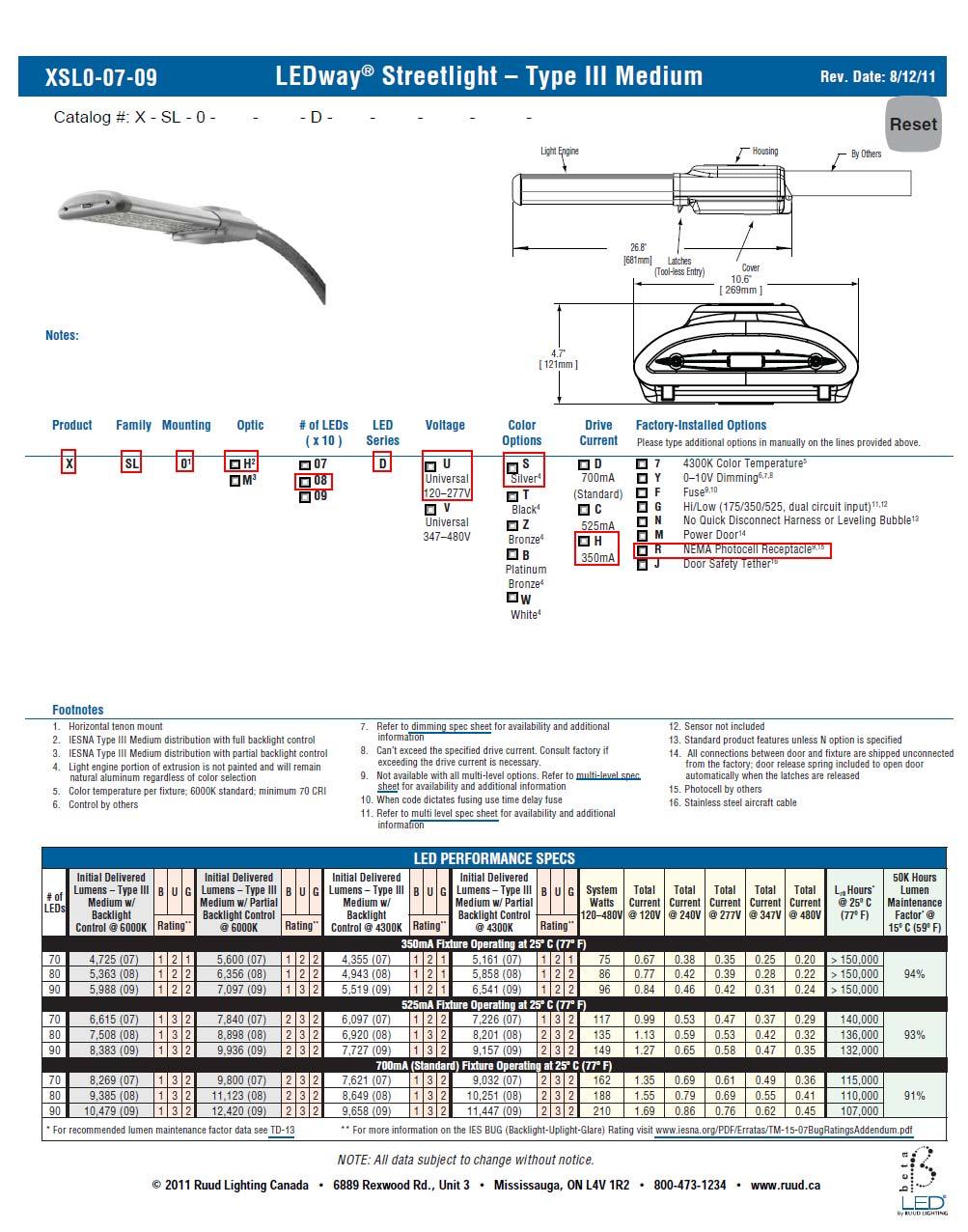
59 59
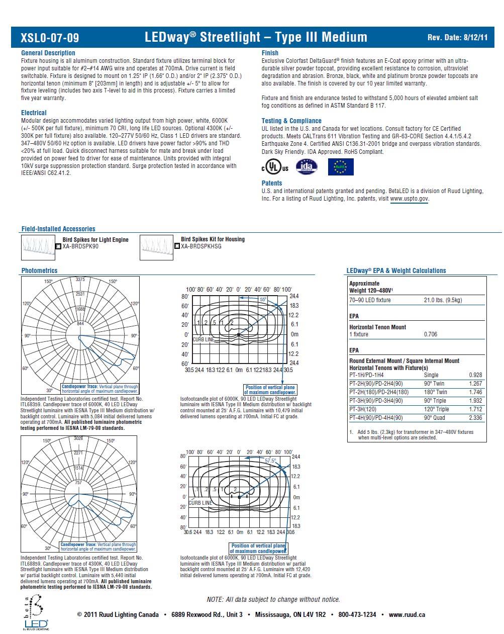
60 60