BIG ENGINEERING AND INSTALLATION GUIDE BLOCK. Retaining Wall FieldStone Face / Stained
|
|
|
- Kevin Darcy Sutton
- 5 years ago
- Views:
Transcription


1 BIG BLOCK ENGINEERING AND INSTALLATION GUIDE FieldStone Face / Stained Monticello New London Alexandria Hutchinson Wadena Morris 12164_LB Engineering Guide 2016_V3.2.indd 1


2 BIG BLOCK ENGINEERING AND INSTALLATION GUIDE FieldStone Face / Stained 12164_LB Engineering Guide 2016_V3.2.indd 2


3 For the last 15 year's LondonBoulder has been providing Engineers and Contractors with the right solution to their BIG retaining wall challenges. With 13 block shapes, three face textures and simple installation, LondonBoulder has proven to be the installer's choice. But don't take my word for it. Call me today and I'll connect you directly with a Contractor or Engineer who can share how the LondonBoulder System has helped their operation. Here's my cell: or visit online at LondonBoulder.com for additional information. Sincerely, Mike Frandsen V.P. Sales / Brown Stain _LB Engineering Guide 2016_V3.2.indd 3

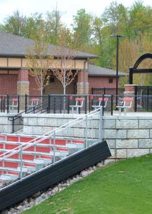
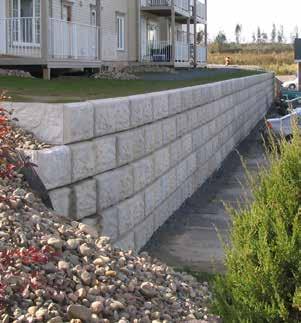
4 FieldStone Face _LB Engineering Guide 2016_V3.2.indd 1


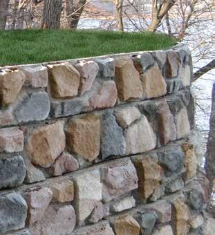
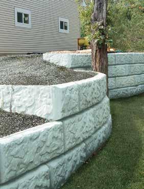
5 FieldStone Face Stained CobbleStone Face Stained _LB Engineering Guide 2016_V3.2.indd 2

6 Product Specifications Height Limits...6 Nearby Structures...7 Utilities...7 Soils...7 Terrain Geometry...7 Grading...7 Design Considerations...8 Water...8 Setback Unreinforced Wall...9 Reinforced Wall...9 Installation Overview Excavation / Base Preparation Anatomy of a LondonBoulder...10 Setting First Course...11 Backfill...12 Installing Successive Courses...12 Geogrid...13 Special Situations...14 Capping / Cap Corners Corners...14 Seawall...15 Free Standing / Partition Wall Wall Design Overview _LB Engineering Guide 2016_V3.2.indd 3


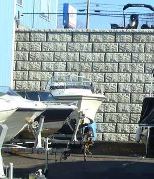
7 LondonBoulder BIG Blocks are available in four depths: 28", 42", 52" and 60". All blocks are designed to fit perfectly together to for efficiencies in your job specification. Compliment your design with any of our 3 available face textures: LimeStone, FieldStone or CobbleStone. Add a finishing touch of stain to turn a plain wall into a work of art. 42" deep blocks Multiple setbacks Multiple face textures Dual face walls Free standing wall LB42 - Left Cap Corner Dimensions: 24" x 18" x 34" Weight: 660 lbs. Sq. Ft. / Block: 3 sq. ft. LB42-42" Full Boulder Dimensions: 48" x 18" x 42" Weight: 2160 lbs. Sq. Ft. / Block: 6 sq. ft. LB42 - Right Cap Corner Dimensions: 24" x 18" x 34" Weight: 660 lbs. Sq. Ft. / Block: 3 sq. ft. When it comes to BIG block walls, we're proud to be the installer's choice. LB42-1/2 Block Dimensions: 24" x 18" x 38" Weight: 900 lbs. Sq. Ft. / Block: 3 sq. ft. LB42-90 Degree Return Dimensions: 48" x 18" x 24" Weight: 1250 lbs. Sq. Ft. / Block: 9 sq. ft. LondonBoulder 6 Cap Unit LondonBoulder Block Units 42 deep TIP - Reach taller heights without geogrid using LB60 and LB52 base blocks. LB42-6" Cap Dimensions: 6" x 40" x 34" Weight: 740 lbs. Sq. Ft. / Block: 1.7 sq. ft. LB42 - Cap Boulder Dimensions: 48" x 18" x 38" Weight: 1260 lbs. Sq. Ft. / Block: 6 sq. ft. 8" LondonBoulder Extended Block Unit 60 deep 52 deep _LB Engineering Guide 2016_V3.2.indd 4


8 52" & 60" deep blocks Build taller without geogrid Multiple setback Multiple face textures Save time and money with less excavation LB " Full Boulder Dimensions: 48" x 18" x 60" Weight: 3150 lbs. Sq. Ft. / Block: 6 sq. ft. LB " Full Boulder Dimensions: 48" x 18" x 52" Weight: 2720 lbs. Sq. Ft. / Block: 6 sq. ft. Multiple shapes Solid or cored Units Dual Sided Units 48" front and 48" back 48" front face tapered unit Geogrid foot option LB28-28" Full Boulder Dimensions: 48" x 18" x 28" Weight: 1396 lbs. Sq. Ft. / Block: 6 sq. ft. LB28-28" Dual Face Dimensions: 48" x 18" x 32" Weight: 1600 lbs. Sq. Ft. / Block: 6 sq. ft. LB28-28" Core Full Boulder Dimensions: 48" x 18" x 28" Weight: 1290 lbs. Sq. Ft. / Block: 6 sq. ft. CORE LB28-28" Core Dual Face Dimensions: 48" x 18" x 32" Weight: 1490 lbs. Sq. Ft. / Block: 6 sq. ft. CORE LondonBoulder BIG Block units are available in three face textures. FieldStone Face CobbleStone Face Stained Stained FieldStone Face Stained CobbleStone Face _LB Engineering Guide 2016_V3.2.indd 5

9 Design Considerations When bringing a project from idea to reality, careful planning at the early stages goes a long way toward minimizing costs, repairs and other project setbacks. Proper consideration of construction site features, obstacles and constraints is essential for a cost-effective design and will influence the final product. UNREINFORCED HEIGHT LIMITS FOR THE LONDONBOULDER 42" BLOCK Assumptions related to engineering: No surcharge or back slope present Soil unit weight of 120 pcf Minimum 1' embedment Backfill compacted to minimum 95% of the standard Proctor maximum dry density. Safety factors: 1.5 against sliding; 2.0 against overturning Heights apply only to soil type with indicated friction angles Construction follows adequate industry practice TIP - Save time and money by incorporating the LB60 and LB52 blocks into the base of a LB42 wall configuration. This allows for taller heights without extensive excavation and having to use of geogrid reinforcements. See photo below. The following chart represents height limits related to vertical or setback walls constructed in soil with varying degrees of friction angles. Chart does not include checks for global stability or presence of water. SOIL NO SETBACK 2" SETBACK 6" SETBACK φ = ' 10.5' 12' φ = ' 10.5' 12' φ = ' 12' 13.5' φ = ' 12' 13.5' φ = ' 13.5' 15' This chart is for estimating tasks and reference only. It is the user s responsibility to ensure that a final, project-specific design is reviewed, approved, and certified by a registered Professional Engineer, based on actual soil conditions. It is the project owner s responsibility to ensure the adequacy of the designed retaining wall incorporated into the overall project through a specification. The specification should include factors which affect the overall integrity of the retaining wall such as location, interaction with other project components, and engineering aspects including but not limited to site soil bearing capacity, global slope stability, presence of underground or surface water, etc. Specification of excavation, trenching or any other construction procedures and corresponding safety specifications are the responsibility of the installer, who shall adhere to sound industry practice and provide additional support during construction if needed. with LB60 and LB52 base _LB Engineering Guide 2016_V3.2.indd 6


10 NEARBY STRUCTURES If they are close to the wall, loads created by structures such as buildings, parking lots, storage areas, etc. can have an impact on final design. Depending on the circumstances and relative duration, these loads may be classified as either LIVE or DEAD. For example, slopes are generally considered DEAD loads, whereas loads coming from parking lots may be classified as LIVE, due to their shorter duration. DEAD loads, e.g., building loads, or loads from a tiered wall may contribute to the overall stability of the wall, depending on closeness to the wall edge. Surcharges increase the stress on block and reinforcing grids. Keep in mind that these facts will contribute to a balanced design. LIVE loads, such as those resulting from bulk storage, vehicular traffic, etc. may act both as stabilizing and destabilizing forces in your design. Typically, a conservative design approach is to neglect any live loads as part of the resisting set of forces in design. As a rule of thumb, surcharge loads that are at a distance of twice the height of a wall below can be neglected in a design. TERRAIN GEOMETRY The first consideration when planning a LondonBoulder wall is to look at the site topography. Careful examination of changes in terrain elevation will help reduce excavation costs. Plan for adequate drainage and other remedies to channel water away from your wall. Other important aspects to consider at this stage are whether adjacent construction, waterways or other terrain features could have an effect on the design and performance of the wall in the future. GRADING Careful examination of terrain grading both above and below the planned wall is essential. Slopes above the wall will create overloads, whereas a sloping grade at the wall footing typically decreases the available resistance to the design loads. Grading can also create problems if it channels or retains water on or near the wall. UTILITIES Utilities should be designed to withstand any loads from the wall system. All utilities that have a potential for leaking (water mains, sprinkler systems) should be moved out of the reinforced soil zone if possible. SOILS Soils are important not only because they will ultimately bear the weight of the designed wall structure, but also because their properties directly affect the design. Typically, well-graded coarse sands have better design properties than finer soils, like clay. Particles in sand fill voids and interlock better than uniform granular soils or clays, resulting in stronger structures. Soils that are expansive, or organic (peats, etc.) should be avoided as fill material when building walls. Granular soils that are too coarse or sharp can damage the reinforcing grid. Consult the grid company for their installation damage reduction factor for a particular soil, that info can be used in the design, and the soil can be used. If the site has unsuitable soils (disturbed soils, soft, expansive, chemically aggressive, etc.) they must be excavated and replaced with appropriate materials prior to any other work _LB Engineering Guide 2016_V3.2.indd 7
, or suspicion of a seasonally shifting water table can dramatically reduce the")


11 Design Considerations WATER One crucial site characteristic that must be checked before any design is carried out is the presence of groundwater. The presence of a water table too close to the bottom of the foundation pad (less than 2/3 the height of the wall), or suspicion of a seasonally shifting water table can dramatically reduce the integrity of the wall if left unchecked. Also, be sure to check for the presence of waterways or moving floodwaters that could cause scour of the foundation at the bottom of the wall. Make sure that terrain features do not bring surface water near the wall. If that is the case, the design should include details to ensure water gets diverted from the structure. These include swales over and around the top of the wall, slopes, curling the ends of the wall into the slope or bank, impervious soil tightly compacted at key locations, etc. These provisions should not be confused with internal drainage within the wall structure, typically comprised of granular aggregate drainage directly behind the wall face, drain tile pipes, and chimney drains behind the reinforced soil mass. Cobblestone Face Stained _LB Engineering Guide 2016_V3.2.indd 8


12 SETBACK One of the benefits of LondonBoulder is its ability to be built both vertically and with multiple setbacks. This level of versatility allows the LondonBoulder line to be useful in a variety of environments while meeting a number of landscaping needs. However, careful consideration must be taken when determining whether to build the wall with or without a setback. Although setback walls have the ability to retain larger amounts of earth than vertical walls, they add a level of difficulty when it comes to project planning and design. Each course in a setback wall has a setback of 2 or 6 inches. If this setback is not considered, the desired layout may be impossible to realize once the minimum radius of curvature of the LondonBoulder units has been reached. All segmental retaining walls designed with active earth pressure theory need to rotate slightly during or after construction. This rotation is caused by construction equipment, tensioning of the geosynthetic reinforcement, and because the soils have to move slightly to achieve stability. The rotation can be as little as 1/2 of a degree or up to several degrees, depending on soil types and the care taken by the contractor. Because of this, vertical walls may not be vertical after construction, but may be leaning out slightly. UNREINFORCED WALLS A retaining wall is a structure that resists the forces from a soil mass by virtue of its own weight. In many cases, a simple gravity wall (with no geogrid reinforcement required) will be all that is needed to retain a soil mass. The soil is kept in place by the sole weight of the stacked concrete blocks. When this weight alone is not enough, the use of reinforcement grid brings together a larger mass of soil to counteract the pressures of the retained soil. Unreinforced walls can be built to heights of 10'-15' depending on the set back of the wall, soil, surcharges and terrain conditions. If soil and terrain conditions are not ideal, it is strongly recommended that the project be reviewed by a qualified licensed professional (P.E.). See Unreinforced Height Limits for LondonBoulder for more detailed information. REINFORCED WALLS When your wall design calls for taller walls, or incorporates special conditions such as tiers, slopes, or surcharges behind the wall, reinforcing grid may be required to stabilize the wall. Grid layers work by bringing together a larger mass to aid the wall in resisting the forces exerted by the retained soil. See grid reinforcement details on page 13. TIP - Consider using the LB28 LondonBoulder when you encounter a retaining wall that will require reinforcement _LB Engineering Guide 2016_V3.2.indd 9

13 Installation Overview EXCAVATION/BASE PREPARATION 1. LondonBoulder recommends that wall elevations be set using a laser level and stakes prior to excavation. This will greatly enhance the efficiency and accuracy of the entire project. 2. Foundation soil shall be excavated to the lines and grades of the construction drawings and as required for base course installation. Use caution to ensure that the foundation is not disturbed beyond the indicated depths. As shown in Figure A, base trench shall be excavated to a minimum of 60" wide and 6" deep for the LB42 Units. Use compacted backfill material to fill over-excavated areas. It is permissible to use a layer of non-woven landscape fabric along the three sides of the trench to maintain a barrier between the surrounding foundation and the base material to be put down later. a. Using granular, inorganic material such as crushed road base material, crushed stone, or recycled concrete, place the base leveling pad in the excavated trench such that it maintains a width of 60" and a minimum depth of 6" after compaction. Compaction should meet or exceed 95% Standard Proctor and should be achieved through the use of a mechanical plate compactor. - or - b. Concrete may be substituted for the granular base material. Granular base material may also be top-dressed with a minimum 3" thick layer of lean and unreinforced concrete. Reinforced footings must be placed below the frost line. 4. Final base must be uniform, level, and well compacted to provide the best possibility for a smooth, hassle-free wall installation. Achieving this standard in the base will also help to limit the number of future repairs that may be necessary due to sections of sagging wall and other base-related failures. 5. Level compacted base material from side to side and front to back. 6. A drainage pipe should be installed in all walls. The drainage collection pipe should daylight into a storm sewer manhole or to a sloped area lower than the pipes behind the walls. The main collection drainpipe just behind the block facing shall be a minimum of 4" in diameter. See Figure D on page 12. Crushed Road Base Material, Crushed Stone, Lean Concrete, etc... Nonwoven fabric (optional) Figure A ANATOMY OF THE LONDONBOULDER Channel Long (front) Face 48" BOTTOM VIEW TOP VIEW Lugs only on Short (back) side BASE PREPARATION/FIRST COURSE Base Course LondonBoulder LB42 Unit 60" Lift Eyes Short (back) Face 4" Drain Pipe (elevation varies) Minimum 6" Pad Base Trench Recommended Construction Tolerances Vertical ± 1" / 10 ft 3" maximum Horizontal Straight lines: ± 1" / 10 ft 3" maximum Rotation From design wall batter: 2º Bulging 1.00" / 10 ft _LB Engineering Guide 2016_V3.2.indd 10
14 SETTING THE FIRST COURSE 1. Always start the base course at the lowest elevation of the wall, if possible. In the case of a base elevation that varies, refer to Figure C. LondonBoulder recommends a two block overlap when stepping up from one course to the next. 2. Place the first course of LondonBoulders directly on the leveling base pad, check to ensure that they are properly aligned and leveled. The bottom surface of each unit should be in full contact with the base. If units have lugs, removing them may be preferred prior to placing as base course. Adjacent units should be in contact with one another at the front face if constructing a retaining wall, and along all inside edges if constructing a partition wall (this is accomplished by reversing every other trapezoidal unit inside the two end units). 3. Alignment of a straight wall may be best achieved by using a string line or laser level on the machined edge of the blocks. If building a convex or concave wall, it may be helpful to run a radius string from an established center point. See Figure B for minimum radius information. 4. Place perforated or slotted PVC or corrugated HDPE pipe behind the course providing the optimal drainage of LondonBoulder units. LondonBoulder recommends that the drain pipe be at least 4" in diameter and surrounded by a minimum of 1 foot of drainage stone. In special situations where water and drainage play a bigger role in the design, weep holes, larger drainage stone, larger drain pipe with sock, and/or filter fabric behind the drainage stone may be warranted. Contact a P.E. for recommendations and details. Figure B TOP VIEW - CURVED RETAINING WALL Minimum Convex Radius with Setback Courses R (*) 1 10'-09" 2 11'-05" 3 12'-00" 4 12'-08" 5 13'-04" 6 14'-00" 7 14'-07" 8 15'-03" 9 15'-11" 10 16'-07" 11 17'-03" 12 17'-10" 13 18'-06" 14 19'-02" 15 19'-10" 16 20'-06" MINIMUM CONVEX RADIUS CONCAVE RADIUS ( * ) Top course or one-course wall leave a 1/4" gap at the back of the block. TYPICAL STEPPING-UP BOULDER CONSTRUCTION DETAIL Figure C _LB Engineering Guide 2016_V3.2.indd 11


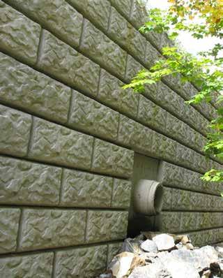
15 Installation Overview BACKFILL 1. All drainage material in the drainfield and infill soils within 3 feet of the wall must be properly compacted. Use appropriate compaction equipment for the soils. 2. Compact in maximum 6" lifts i.e. compaction should occur a minimum of 2 times with each course of LondonBoulder units set. 3. Place drainage aggregate behind and up to the height of the LondonBoulder wall. Drainage aggregate shall be placed to a minimum thickness of 12" measured from the back of the LondonBoulder unit. Reference photo to the right. 4. If installing a retaining wall, it is likely that there will be triangular voids between each LondonBoulder that are caused by the trapezoidal shape of the units. (Note that this void will not be present if installing a partition wall). Fill this void with 3/4" - 1 1/2" crushed rock or as specified on your project. 5. Large rock and fat clay soils should generally be avoided as backfill material unless approved by a qualified engineer. In addition, soils that are excessively wet, dry, frozen, or inundated with debris should not be used. 6. If required, install geotextile filter fabric between the compacted backfill material and compacted infill soil. INSTALLING SUCCESSIVE COURSES 1. Ensure the drainage aggregate is level with, or slightly below the top of the LondonBoulder unit. 2. Clean all excess material from the top of the units as well as any debris that may have fallen into the channels that run parallel across the top of each LondonBoulder. Even a small stone can create unevenness or a wobble. 3. Place the next row of LondonBoulder units with the seams offset from the seams of the units below. 4. If installing a 6" setback place the lugs to engage the back edge of the units below. 2" and 0" setback LondonBoulders are manufactured for the lugs to set into the channel of the unit below. 5. Set up a string line horizontally down the wall to ensure wall straightness. Adjust units as needed to form straight lines and smooth curves. Make sure to check each block to certify that it is level from front to back and side to side. Adjust if necessary. Qualified geogrid material can be used as a shim to make minor corrections in level. 6. Place drainage aggregate and infill soil as stated previously. 7. Repeat these steps until the wall reaches its final height. 7. If using geogrid reinforcement, be sure to avoid using compacting equipment directly on geogrid. Place the next 6" lift of soil on top of the grid before compacting. Minimum of 12" VARIOUS DRAINTILE DAYLIGHT CONSTRUCTION DETAILS Side View Side View Around Block Daylight Drain 4 PVC In-Block Daylight Drain 4 PVC Block-Notch Daylight Drain Figure D _LB Engineering Guide 2016_V3.2.indd 12
16 USING THE GEOGRID SYSTEM 1. Install units up to the designated height of the first grid layer, making sure to backfill and compact behind the wall to a depth equal to the designed grid length. 2. Cut grid to design length as shown on the plans. Make sure the grid is positioned on the top of the unit course 2" to 3" from the face. This will help to keep each successive course flat. Install the grid with the design strength direction perpendicular to the wall face. Seams or overlaps of grid parallel to the wall face are not permitted. 3. The geogrid reinforcement must be laid level upon the block and upon level backfill, compacted to 95% Standard Proctor density. 4. Remove all slack in the geogrid, then anchor it to the compacted backfill and place the next level of LondonBoulders and backfill. These units should be placed on top of the grid. 5. Only hand-operated equipment should be allowed within 3 feet of the wall. Track construction equipment shall not be operated on less than 6" of compacted infill material. GEOGRID LAYOUT IN CURVES AND CORNERS Curves and corners in designs need additional considerations for the correct layout of the reinforcing grid. Interior corners will invariably leave gaps between grid layers, due to the curvature. To cover these gaps, install additional reinforcement in places where gaps occur on the next course above prior to backfilling. See Figure F. In addition, square corners require that the 90 gap be filled with an extension of the reinforcing sheet equal to 25% of the total wall height, on alternate sides of the gap as you go up. See Figure H. If it's not possible to add on the next course to put 3" of fill between the grid layers. In contrast, exterior corners will always cause reinforcing grids to overlap, which in turn dramatically reduces the load carrying capacity of the grid. To correct this, a minimum of 3" fill must be placed between sheets at those overlap areas prior to backfilling that lift, as shown in Figure G, and Figure I. INSIDE CURVE GRID LAYOUT (TYP) Inside Curve Grid Layout (TYP) Inside Curve Grid Layout (TYP) OUTSIDE SQUARE CORNER REINFORCEMENT LAYOUT (TYP) Figure F Outside Curve Grid Layout (TYP) Outside Curve Grid Layout (TYP) INSIDE SQUARE CORNER REINFORCEMENT LAYOUT (TYP) OUTSIDE CURVE GRID LAYOUT (TYP) Scale: NTS STEP #1: Place grid so as to minimize overlap. Place 3" fill between any overlapping edges Figure I STEP #2: Install the next block course. Mark those blocks where there were gaps left in the grid below. Backfill and compact. Figure H STEP #3: Place grid over the areas where gaps were left. Backfill and compact. If overlapping, fill as in Step #1. Figure G _LB Engineering Guide 2016_V3.2.indd 13


17 Special Situations CAPPING 1. Make sure the surface of the Cap Boulder, and the block the Cap Boulder is being placed on, is dry and free of debris. 2. Set cap unit in the same manner as LondonBoulder units. 3. The back side of the Cap Boulder is recessed 8 inches to allow for the application of soil, sod, rock, mulch or any other fill material the end user deems necessary. The Cap Boulder s sides are tapered to allow for a radius wall if desired. LondonBoulder also offers a 6" cap boulder as an alternative for capping. 6" caps are designed to be placed on the top course using concrete adhesive between it and the course below. 4. Each end of a course of Cap Boulders can be finished with a Left and/or Right Cap Corner. 5. Careful consideration must be taken when using the Cap Corner units at both ends of a wall with two 90 corners. Given the set dimensions of the Cap Corners at 24", some calculations must be made to ensure that it is possible to fit a set number of units between the two end units. Cutting of Cap Boulders may be required to maintain running bond or to get all caps to fit without gaps. 90 DEGREE CORNERS Utilizing its rebar pinning method, LondonBoulder s 90 Return Corner provides a simple, 1-unit system to turn a 90 corner without losing retention strength. Each 90 Return Corner is manufactured with a 3" hole running vertically through the unit. By alternately flipping and turning each course, these holes will create a corner core into which rebar can be inserted. Since these units are manufactured without lugs for versatility, the rebar pinning system serves as the shear connection for a strong, reliable corner. See Figure J. This method of achieving 90 Corners also continues the 1/2 bond both directions, creating a consistent finish. 90 DEGREE RETURN BOULDER CAP BOULDER 90 DEGREE CORNER 6" CAP BOULDER CAP CORNER BOULDER TOP VIEW Stained Tan Figure J _LB Engineering Guide 2016_V3.2.indd 14


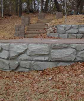
18 FREE-STANDING PARTITION WALL With a combination of unique and versatile features including vertical capabilities and a textured face on two sides, the LondonBoulder line can be easily turned into a free standing partition wall. Incorporate a curved freestanding wall into your design with the LB28 Dual Face Core units. Simply trim the tabs to fit the desired curves. See inset photo below. TIP - Create a custom curved freestanding BIG Block wall by simply cutting the tabs of the LB28 Dual Face Core units. See inset below. LB28 Dual Face Core / Free Standing Wall Limestone Face - Tan Stain LB28 Dual Face Free Standing Wall SEAWALL With minor changes to the base leveling pad and the addition of rip rap, LondonBoulder walls can be installed in water settings. However, due to the variety of site-specific variables and restrictions, no wall height charts can be provided for seawall applications. Consult your P.E. for specific details and stamped drawings. See Figure K. Typical Water Level TYPICAL SEAWALL DETAIL Slope Varies Non-Woven Geotextile Fabric 1" Drain Stone [1'-0" thick minimum] CobbleStone Face Figure K 12" Rip Rap on Non-Woven Geotextile Fabric _LB Engineering Guide 2016_V3.2.indd 15


19 Wall Design Overview UNREINFORCED / REINFORCED When it comes to flexibility in unreinforced and reinforced BIG Block walls, we have you covered. LondonBoulders fully engineered BIG Block walls system provides you with unmatched flexibility without breaking the bank. The LB42, LB52 and LB60 are the primary blocks for most BIG Block walls. All shapes are engineered to fit together for strength and flexibility. We've created typical wall construction detail drawings to help determine which engineered solution is best for your application. For immediate access, visit us online at: drawings All files are available as PDF and dwg formats. YOU DON'T ALWAYS HAVE TO USE GEOGRID ON TALL WALLS. Our fully engineered BIG block system allows you to build walls up to 16.5' without the additional cost and expense that geogrid produces. Wall cross sections below are using ideal soil, surcharge, slope and safety factors in the design 10.5' Tall 13.5' Tall 16.5' Tall The LB42 units can build an unreinforced wall up to 10.5' With LB42, LB52 and LB60 units reach heights up to 13.5' Use the LB42 and LB60 units for unreinforced walls up to 16.5' Diagrams are not to scale DISCLAIMER: The suggested design materials presented in this manual are for estimating tasks and reference only. It is the user s responsibility to ensure that a final, project-specific design is reviewed, approved and sealed by a registered Professional Engineer, based on actual soil conditions. It is the project owner s responsibility to ensure the adequacy of the designed LondonBoulder retaining wall incorporated into the overall project through a specification. The specification should include factors which affect the overall integrity of the retaining wall such as location, interaction with other project components, and engineering aspects including but not limited to site soil bearing capacity, global slope stability, presence of underground or surface water, etc. Specification of excavation, trenching or any other construction procedures and corresponding safety specifications are the responsibility of the installer, who shall adhere to sound industry practice and provide additional support during construction if needed LondonBoulder _LB Engineering Guide 2016_V3.2.indd 16


20 FieldStone Face _LB Engineering Guide 2016_V3.2.indd 17