CORK INSTITUTE OF TECHNOLOGY INSTITIÚID TEICNEOLAÍOCHTA CHORCAÍ. Summer Examinations 2009/10. Bachelor of Science in Process Plant Technology
|
|
|
- Lorin Stella Shaw
- 5 years ago
- Views:
Transcription
1 CORK INSTITUTE OF TECHNOLOGY INSTITIÚID TEICNEOLAÍOCHTA CHORCAÍ Summer Examinations 2009/10 Module Title: Process Plant Services Module Code: MECH8018 School: Mechanical Engineering. Programme Title: Programme Code: Bachelor of Science in Process Plant Technology EPPTE_8_Y4 External Examiner(s): Mr N Kingston, Mr J Phelan Internal Examiner(s): Mr W Bateman (Section B) Ms. M. Cullinane (Section A) Mr. James Kehoe (Night class lecturer) Instructions: Duration: Answer any 3 questions. All questions carry equal marks. Answer Section A and Section B in separate answer books. 2 hours. Sitting: Summer 2010 Requirements for this examination: Attachments to be provided, for student reference, with this exam paper. 1 Steam Pipeline Sizing Chart Pressure Drop Q1 (with paper) 2 Pressure Enthalpy Chart HFC-134a Q2 (with paper) 3 Vapour Pressure V s Water Temperature. Q3 (with paper) 4 CIBSE Table C4.36 Velocity pressure loss factors Q3 (with paper) 5 CIBSE Table C4.16- Water at 10 Deg C Heavy Grade Steel. Q3 (with paper) 6 Lowara Pump Data Sheet 04236D for model HTF Q3 (with paper) 7 CIBSE Table C4.11 page 4-17 Water 75 C Heavy Steel. Q4 (with paper) Note to Candidates: Please check the Programme Title and the Module Title to ensure that you have received the correct examination paper. If in doubt please contact an Invigilator. Page 1 of 11
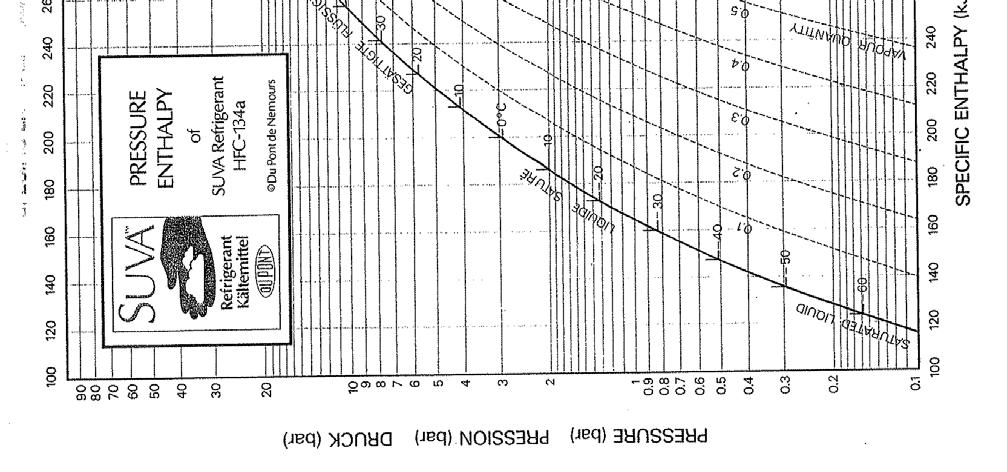
2 Section A Steam & Refrigeration Q1 (a) Plant steam is generally generated and distributed at higher pressure with pressure being reduced locally for individual users. Briefly explain two advantages. [4 marks] (b) With the aid of a neat sketch show the components of a steam pressure reducing set. [6 marks] (c) Three reactor vessels must be supplied with steam from a main header pipe operating at 30 Bar g. Vessel No 1 has a demand of 10,000 kg at 7 bar g. Vessel No 2 has a demand of 5000 kg/h at 3 bar g. Vessel No 3 has a demand of 15,000 kg/h at 20 bar g. Size the 3 branch pipes and the main header pipe using the pressure drop chart. The branch pipe work must be designed to have a maximum dp of 0.5 bar/100m. The main header must be designed to have a max dp of 0.1 bar/100m. [4 marks] Reference 1 Steam Pipeline Sizing Chart Pressure Drop Q1 (with paper) (d) Briefly explain why water hammer occurs in steam lines. Explain how water hammer can be reduced by the correct design of the steam pipe work. [6 marks] Q2 (a) Describe with the aid of a neat sketch a typical refrigeration circuit. Label the four major components. Use arrows to indicate the direction of flow. Indicate relative pressures and liquid / gas phases after each of the four major components. [6 marks] (b) Where does flash gas occur in the refrigeration circuit. Explain how flash gas occurs and why it is useful to the refrigeration cycle. [4 marks] (c) What does the term C.O.P refer to in a refrigeration system. Write down the formula for C.O.P and give details of which points should be considered on the pressure-enthalpy diagram when calculation C.O.P. [4 marks] (d) Plot the phases of the following refrigeration cycle on the attached pressure-enthalpy chart. Use the information on the chart to calculate the C.O.P for this cycle. [6 marks] Point A - Outlet of Condenser Absolute pressure 9.6 Bar a Temp 38 C Point B - Inlet to Evaporator Absolute pressure 3.3 Bar a Temp 4 C Point C - Outlet of Evaporator Absolute pressure 3.3 Bar a Temp 4 C Point D - Outlet of Compressor Absolute pressure 9.6 Bar a Temp 40 C 2 Pressure Enthalpy Chart HFC-134a Q2 (with paper) Page 2 of 11
3 Section B Pipe work systems. Q3 (a) The following diagram shows an open tank positioned below the suction of the pump. Determine if the pump shown will cavitate under the operating conditions shown. Show all calculations. [15 marks] Mild steel pipe between open tank and pump. welded mild steel elbows Globe valve A2/A1=1.0. For CIBSE Table C No. In-line strainer zeta = 3.0 Pump Details Lowara HTF Q=8900 l/h NPSHr = From Data sheet 1 m 3 m Water 10 Deg 3 m 1 m (b) The production personnel predict a situation where the water temperature in the tank may increased to 70 Deg C on some occasions. Neglecting any change in flow velocity due to higher water temperature, clarify if the change in water temperature alone, would cause the pump to cavitate. [5 marks] Reference - 3 Vapour Pressure V s Water Temperature. Q3 (with paper) 4 CIBSE Table C4.36 Velocity pressure loss factors Q3 (with paper) 5 CIBSE Table C4.16- Water at 10 Deg C Heavy Q3 (with paper) Grade Steel. 6 Lowara Pump Data Sheet 04236D for model HTF Q3 (with paper) Page 3 of 11
4 Q4 Pipe work and pump sizing. Pump and pipe work sizing required for the transfer of l/h of water to one of four possible points. Only one route is enabled at any one time, i.e. from pump to one of following A. To bottom fill silo 1. B. To CIP nozzle silo 1. C. To bottom fill silo 2. D. To CIP nozzle silo 2. Use steel pipe and fittings. Use all welded joints. Use a target water flow velocity of 1 m/s. (a) Estimate the pipe diameter for each section of pipe. [5 marks] (b) Identify the index run and specify overall flow and pressure requirements for the pump required to transfer water along that index run. [15 marks] 2,5 m 2,5 m 0,7 m 0,7 m CIP Nozzle CIP Nozzle SILO No.1 SILO No.2 1 m 5,8 m Mild steel pipe work on all pipe runs welded mild steel elbows All valves are actuated Diaphragm valves w/d = 1.0. For CIBSE Table C4.36. CIP nozzle requires residual pressure of 3 bar at inlet to nozzle. Bottom Fill connection 5,8 m 1 m Only one route in use at any one time i.e from pump to one of A. Silo 1 bottom fill. B. Silo 1 CIP nozzle C. Silo 2 bottom fill. D. Silo 2 CIP nozzle Pumped Volume Q=18,000 l/h Water at 75 Deg C Bottom Fill connection 1 m 6 m CIBSE Table C4.11 page 4-17 Water 75 C Heavy Steel. Q4 (with paper) CIBSE Table C Velocity press loss factors. Q4 (with paper) Page 4 of 11


5 Page 5 of 11


6 Page 6 of 11
7 Page 7 of 11
8 Page 8 of 11
9 Page 9 of 11

10 Page 10 of 11
11 Page 11 of 11