Composites in Automotive Bangkok July 2017
|
|
|
- Iris Lyons
- 5 years ago
- Views:
Transcription
1 Composites in Automotive Bangkok July


2 About CCS CHIA Thien Fook Peter HO Florian DOETZER Jerry ANG LIM Chee Meng Klaus DRECHSLER The leadership team combines more than 100 years of combined industry experience Composite Cluster Singapore is active in consulting, engineering, manufacturing and training for advanced composites Together with its partners, CCS provides the full spectrum of composites solutions, from early-stage feasibility assessments to manufacturing of components CCS s mission is to develop new and innovative technologies for high-performance composites products and be a regional competence center to enable customers for global markets. It is our mission to provide the best possible solutions, based on state-of-the-art technologies to our customers for maximum market impact 2


 Fibersim Laminate: 6 mm Helical Windings, 2 mm Hoop")
 significant")


 16.03.")


 Consideration of")


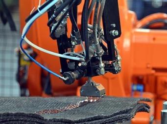
3 Automated fiber placement export/import Compliance to avoid slip-off between Liner and Boss Benefits Eliminates the need to manually create manufacturing documentation for hand layup processes Increases production throughput and quality by removing the ambiguity in hand layup manufacturing processes Composite Manufacturing Solutions Seamlessly transfers design data to automated production systems KoWaD /15 Press-FitBushing to seal between Liner and Boss Repeatability of the hand layup manufacturing process can be ensured by eliminating the manual creation and digitization of ply templates, incorporating laser assisted layup and creating process documentation that removes ambiguity. Automated tape laying and fiber placement ensure repeatability and eliminate ambiguity, but the composite definition is often manually created for path planning and post generation. Publish Fibersim Composite Format CCS Activities Automotive Fibe doc han rep by d pro Composite Pressure Vessels Numerical Analysis Fibe inte ma incl aut aut and O-Ring to seal between Valve and Boss Iteration 0 Laminat Stress Effort (Fiber Fracture / Tension) Fibersim Laminate: 6 mm Helical Windings, 2 mm Hoop Windings Burst Pressure 705 bar Analysis of Cuntze Stress Effort regarding Failure Mode 1 (Fiber Fracture / Tension) significant reduction in wall tickness in next iteration steps due to low laminate stress effort CAD Design Numerical Analysis Numerical Analysis KoWaD /15 Iteration 0 FEA-Model (The Colour of the Elements in the figure is random) Hoop Windings 90 Cylinder ca. 15 Dome ( ) FEA-Modell with Geodesic Liner Geometry and estimated Wall Thickness (6mm) Iteration 0 Automated tape laying export Combination of Injection Moulding and Thermoforming More examples One Stage Process 29 Umformen und Umspritzen von Organoblechen Prozessvarianten Ein-Stufen-Prozess 30 Additional Hoop-Windings on Cylinder (2mm) Enlacement of Boss (90 ) for first Iterations simplified Boss-Geometry Boss (isotropic) Consideration of Contact between Boss and Reinforcment in further Iterations Combination of Injection Moulding and Thermoforming Infotainment carrier and Thermoforming Combination of Injection Moulding FEA Model KoWaD /15 Infotainment carrier Handling ComposiCAD Heating Handling Thermoforming Injection Moulding Thermoplastic Composite Processes Handling Stacking Multi Material Multi-material backrest Overmolding of Reinforcements Nonwoven CF Tapes Injection Material Back Panel Reinforcement Ribs CF UD Tapes Metal Insert Local Reinforcement Recliner Connection Organic Sheets Polymer Finished part 2015 KraussMaffei Technologies GmbH 2015 KraussMaffei Technologies GmbH 3


4 Regulations aimed at reducing emissions and improving fuel efficiency Reducing vehicle lightweight 46% Lightweight vehicles 48% Automotive companies must drastically rethink the way vehicles are engineering and manufactured to comply with government regulations. Source: How Prepared Is the Automotive Industry? Solutions for Meeting Fuel Efficiency and Emissions Standards Aberdeen Group, Inc.,


5 Automotive Composites Are Unique High production rates cycle times of 4 minutes or less Lower cost material forms and processes fast forming, braiding, localized fiber placement, pultrusion, spray-up, thermoplastics, special/custom weaves Greater shape complexity More frequent design iterations
6 Challenges in High Volume Automotive Composite Applications Economics Time to market much less than aerospace industry Cost driven Material Compatibility Process/material selection and modeling Rapid forming 2D to 3D Design/Manufacturing Processes Complex shapes, changes often New material forms/processes High production rates, fast cycle times Performance Criteria Analysis Tight coupling between CAE/ Design/Manufacturing Predictability with less safety margin


7 Manufacturing Challenges Process / Tooling Fiber Direction Drapeability POINT LINE 2-STAGE Lay-Up Balancing Load Path Drop-offs & zone transitions Reduction of Scrap Initial Stack-up Redefined


8 Automotive Composite Engineering Multi-Directional Data Flow ANALYZE (CAE) DESIGN (CAD) MANUFACTURE


9 Material Properties May Vary Over Part Surface Metallic Isotropic Composite Non-Isotropic Misalignment Angle 15 degree misalignment 80%+ strength reduction Properties Equal Properties vary based on material, process, geometry


10 Process Parameters Can Impact Fiber Orientations Same Material Same Shape Flat Patterns POINT LINE 2-STAGE ~15 Deg. Difference Only in Process Parameters Initial Tool Contact


11 Automotive Laminate Design Method Schematic Initial Stack-up Redefine Sequence


12 Automatic Surface Offset for Digital Mockup and Tooling Design Create parametric surface offsets with ramps from overlay reinforcements Ramps for Drop-offs

13 True Fiber Orientations Fiber Deviation Simulation


14 Design Producible Plies


15 NCF Material Simulation Uni conforms well 0/+45/-45 less compliant 0/+45/-45/90 manufacturing issue


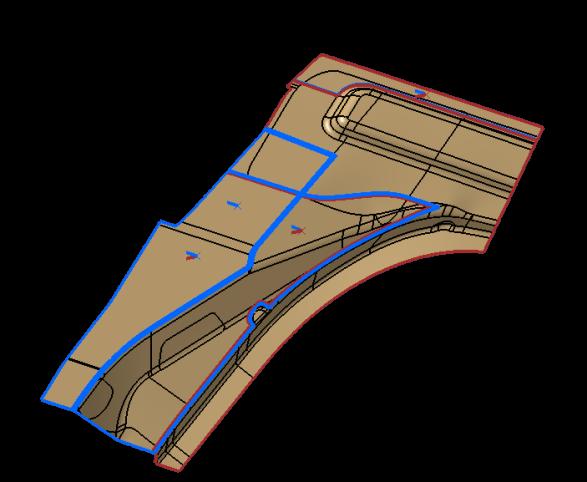
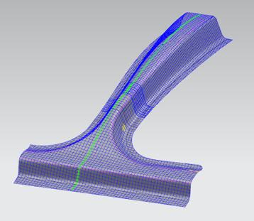
16 Formed Part Development Tools Visual indicators and color coding can be used to guide forming strategies Formed laminate = relative motion between plies Blue = little to no relative motion Red = significant relative motion between plies t 2D laminate positions plies in 2D blank for proper forming to 3D


17 Support End-to-End Engineering Process Workflow Plus a Seamless Link to Manufacturing CAD surface Design, Producibility, Analysis Iterations Bi-Directional Analysis Interface Design Validation Auto-generate Flat Patterns, Manufacture Data Optimize For Light Weight Iterative loop Define Laminate Open CAE Architecture Accurately Solve for Stiffness, Strength, Thermal, NVH, Acoustics, Durability, Crash Auto-generate Drawings and Documents 17


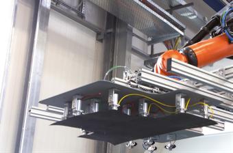
18 Automated Generation of Data and Documentation Manufacturing documentation and automation PLM Feeds Delivering accurate design data to the manufacturing floor Drawings The highest quality, lowest cost product import export ment osite n for by y in ing requires repeatability of the manufacturing process. You can achieve this by using accurate information, eliminating ambiguity and increasing the use of process automation. Repeatability of the hand layup manufacturing process can be ensured by eliminating the manual creation and digitization of ply templates, incorporating laser assisted layup and creating process documentation that removes ambiguity. Automated tape laying and fiber placement ensure repeatability and eliminate ambiguity, but the composite definition is often manually created for path planning and post generation. The Analysis Interface drives analysis from the same single CAD master model that is used for design and manufacturing. This permits analysis to be performed on a part in its to be-manufactured state. Data for Weight - Cost Ply-book sign uction Fibersim helps you quickly and accurately create documentation and data directly from the composite manufacturing representation, ensuring that the documentation and automated production system data are always current and accurate. Fibersim generates plybook documentation needed for hand layup, which ensures repeatability and part quality by displaying the layup process. Flat Pattern Export Fibersim manufacturing interfaces support myriad manufacturing processes, including automated cutting, automated fiber placement, automated tape laying and laser projection. Laser Projection 9 18


19 Direct 3D Link to Manufacturing part model cutting pick/place fiber place forming injection

20 Our Solution As SIEMENS Channel Partner, we offer you: Direct integration with PLM workflow Saves over 50% in design efforts Full support for composite automotive manufacturing Production-proven success addressing the challenge of engineering lightweight structures for 20+ years with the Fibersim portfolio of software. Supports NX, CATIA and Creo platforms Works inside native CAD Bidirectional links to CAE Reduces manufacturing scrap by 90% Improves quality and reduces risk Automates capturing of design intent Ensures accuracy with design changes 20

21 Contact Us! Composite Cluster Singapore SIEMENS Channel Partner 6 Penjuru Close, Singapore Copyright 2017, Composite Cluster Singapore 21