HISTORY OF CONSTRUCTION FOR EXISTING CCR SURFACE IMPOUNDMENT PLANT GORGAS GYPSUM POND 40 CFR (c)(1)(i) (xii)
|
|
|
- Jean Harrington
- 5 years ago
- Views:
Transcription
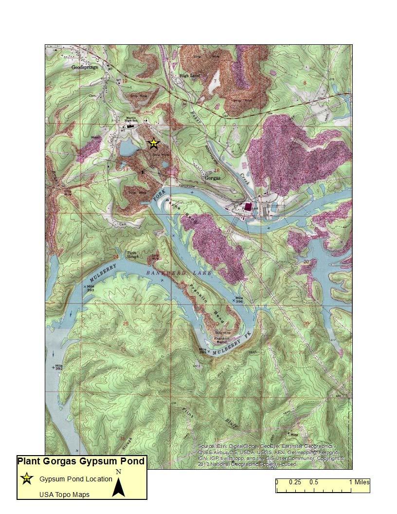
1 HISTORY OF CONSTRUCTION FOR EXISTING CCR SURFACE IMPOUNDMENT PLANT GORGAS GYPSUM POND 40 CFR (c)(1)(i) (xii) (i) Site Name and Ownership Information: Site Name: William C. Gorgas Electric Generating Plant Site Location: Site Address: Parrish, Alabama 460 Gorgas Rd. Parrish, Alabama Owner: Address: Alabama Power Company 600 North 18 th Street Birmingham, AL CCR Impoundment Name: NID ID: Plant Gorgas Gypsum Pond NA EPA s Disposal of Coal Combustion Residuals from Electric Utilities Final Rule (40 C.F.R. Part 257 and Part 261), (c)(1), requires the owner or operator of an existing CCR surface impoundment to compile a history of construction. To the extent feasible, the following information is provided: (ii) Location of CCR Unit: , See Location Map in the Appendix (iii) Purpose of CCR Impoundment: The William C. Gorgas Electric Generating Plant is a 5 unit electric generating facility, all of which are coalfired units. The Plant Gorgas Gypsum Pond is designed to receive and store coal combustion residuals (gypsum) produced during the electric generating process at Plant Gorgas. The gypsum slurry from the flue gas desulfurization operation is wet sluiced to the gypsum storage area. The gypsum is allowed to settle and the water decants to the sedimentation pond. The decant water flows from the sedimentation pond to a clear pool before it is returned to the scrubber process. (iv) Watershed Description: Plant Gorgas is located within the Baker Creek Mulberry Fork HUC 12 watershed which has a total area of 37,044 acres. The Baker Creek Mulberry Fork Watershed is located within the Mulberry HUC 8 watershed which has a drainage area of 878,212 acres. No run on from the surrounding watershed flows into the Gypsum Pond.
2 (v) Description of physical and engineering properties of CCR impoundment foundation/abutments: The Plant Gorgas Gypsum Pond is located within the Warrior Basin physiographic region of the Cumberland Plateau and is a subsection of the Appalachian Plateaus physiographic province. The Warrior Basin consists of a broad upland with moderate relief, and is formed on gently dipping strata of the Pottsville Formation. The upper reaches of the surface geology are dominated by the Pratt Coal Group and the Cobb Coal Group consisting of shale, siltstone, sandstone, and coal seams. The specific area of the Gypsum Pond was filled with mine spoil after previous surface mining activities. Borings taken in the undisturbed areas of the site suggest that only a thin layer of soil (5 to 20 feet) was present above the residual Pottsville Formation. General soil conditions in most areas consisted of dark gray to black, fine to gravelly, shale and sandstone coal mine spoils. The topography of the area was variable. A terrace type stratigraphy exists at the gypsum storage location due to the previous strip mining operations and backfilling of this area with mine spoils. (vi) Summary of Site Preparation and Construction Activities: The Gypsum Pond was constructed in An area approximately 50 acres in size was used to create the first cell of the gypsum storage area. The Gypsum Pond itself covers approximately 18 acres. There is an area to the east at a lower elevation that consists of a sedimentation pond, clear pool, and an emergency storage pond. The ponds are lined with an HDPE liner. As a part of construction, the existing soils/minespoil was graded, the subgrade proofrolled and a granular fill was placed beneath the liner. Embankments were constructed of compacted soil fill obtained from nearby borrow pits. Subsequent to initial construction, the downstream slopes of the embankment were surfaced with limestone riprap. (vii) Engineering Diagram: The following drawings reflecting the construction of the Plant Gorgas Gypsum Pond can be found in the Appendix: 2007 Site Grading Plan 2007 Cell Sections and Details 2007 Grading Plan Pond Sections and Details 2007 Grading Details (viii) Description of Instrumentation: There is currently no instrumentation at the Plant Gorgas Gypsum Pond.
3 (ix) Area capacity curves: Cumulative Volume in Acre Feet Plant Gorgas Gypsum Pond Area Capacity Curve Elevation of Pond in Feet (NAVD) Surface Area in Acres Volume Capacity Surface Area (x) Spillway/Diversion design features and capacity calculations: The Plant Gorgas Gypsum Pond spillway design consists of a 48 inch HDPE riser pipe that connects to a 36 inch pipe that discharges into the sedimentation pond. There is an additional 36 inch HDPE pipe that collects stormwater runoff from the perimeter ditch and discharges into the same 36 inch discharge pipe. The combined capacity of this discharge structure is approximately 100 cfs at a pond elevation of ft. (xi) Provisions for surveillance, maintenance and repair: Inspections of dams and dikes are critical components and are conducted on a regular basis at least annually by professional dam safety engineers and at a minimum interval of every seven days by qualified persons at the plant. In addition, inspections are performed after unusual events such as storms. The inspections provide assurance that structures are sound and that action is taken, as needed, based on the findings. Specific items addressed during the inspections include observations of pond levels, weather conditions, rainfall since the prior inspection, conditions of slopes and drains, erosion, animal damage, ant hills, alignment of retaining structures and more. Dam safety engineers assess any maintenance or remediation performed since the previous inspection, check the status of work recommended at prior inspections, ensure that the posting of emergency notification information is up to date and evaluate any items noted during plant personnel inspections.
4 Construction Specifications: The following specifications relevant to the construction of the Plant Gorgas Gypsum Pond can be found in the Appendix: 2007 Technical Specifications for New Gypsum Storage Facility 2007 General Notes (xii) Known record of structural instability: There are no known instances of structural instability at the CCR unit.
5 Appendix
6
7
8
9
10
11
12
13
14 INQUIRY NUMBER GENERAL TECHNICAL SPECIFICATIONS FOR EARTHWORK FOR NEW GYPSUM STORAGE FACILITY FOR PLANT GORGAS - UNITS 8, 9 AND 10 FGD PROJECT AT GORGAS STEAM PLANT Prepared For ALABAMA POWER COMPANY By SOUTHERN COMPANY SERVICES, INC. EARTH SCIENCE AND ENVIRONMENTAL ENGINEERING REV DATE DESCRIPTION BY CHK D 0 6/12/06 Issued for Construction SSS HLH CIVIL APPR KAM/ RCB ELECT APPR I/C APPR MECH APPR MGR APPR DHF
15 INQUIRY NUMBER GENERAL TECHNICAL SPECIFICATIONS FOR EARTHWORK FOR NEW GYPSUM STORAGE FACILITY FOR PLANT GORGAS - UNITS 8, 9 AND 10 FGD PROJECT TABLE OF CONTENTS 1.0 APPLICABLE DOCUMENTS SUBMISSIONS BY CONTRACTOR SEDIMENT AND EROSION CONTROL CLEARING, GRUBBING, AND STRIPPING FILL MATERIALS AND PROCEDURES DEWATERING GRASSING AND SLOPE PROTECTION 9
16 INQUIRY NUMBER GENERAL TECHNICAL SPECIFICATIONS FOR EARTHWORK FOR NEW GYPSUM STORAGE FACILITY FOR PLANT GORGAS - UNITS 8, 9 AND 10 FGD PROJECT ALABAMA POWER COMPANY PARRISH, ALABAMA 1.0 APPLICABLE DOCUMENTS 1.1 CODES AND STANDARDS The following Codes, Standards, Specifications, Publications, and/or Regulations shall be made part of these Specifications and will become part of the contract entered into for performance of the work covered herein. The latest edition in effect at the time of the contract shall apply. A. U.S. Department Of Labor, Occupational Safety and Health Administration (OSHA). OSHA 29 CFR Safety and Health Regulations for Construction B. American Society for Testing and Materials (ASTM) Standards: ASTM D420 - Standard Guide to Site Characterization for Engineering Design and Construction Purposes. ASTM D422 - Standard Test Method for Particle-Size Analysis of Soils. ASTM D698 Test Method for Laboratory Compaction Characteristics of Soil Using Standard Effort ASTM D Standard Test Method for Density and Unit Weight of Soil in Place by the Sand-Cone Method. ASTM D Standard Test Methods for Laboratory Compaction Characteristics of Soil Using Modified Effort ASTM D Standard Test Method for Laboratory Determination of Water (Moisture) Content of Soil and Rock by Mass. ASTM D Standard Practice for Classification of Soils for Engineering Purposes (Unified Soil Classification System). 1
17 ASTM D2488 Description and Identification of Soils (Visual-Manual Procedure) ASTM D Standard Test Methods for Density of Soil and Soil- Aggregate in Place by Nuclear Methods (Shallow Depth). ASTM D2937 Test Method for Density of Soil In Place by the Drive Cylinder Method ASTM D Standard Test Method for Water Content of Soil and Rock in Place by Nuclear Methods (Shallow Depth). ASTM D Standard Test Methods for Liquid Limit, Plastic Limit, and Plasticity Index of Soils. ASTM D4643 Test Method for Determination of Water (Moisture) Content of Soil by the Microwave Oven Method ASTM D4959 Test Method for Determination of Water (Moisture) Content of Soil by Direct Heating Method C. The Storm Water Management For Construction Activities - Developing Pollution Prevention Plans And Best Management Practices Document, as amended, as adopted by the EPA D. The Alabama Nonpoint Source Management Program Document, as amended, as adopted by the Department and approved by the EPA. 1.2 REFERENCES Geotechnical Investigation Soil test borings and rock cores have been performed in conjunction with the Subsurface Investigation for this area. This report and logs of these borings are included with this specification. The title of this report is, Gorgas Steam Plant, Subsurface Investigation Report for Gypsum Storage Area, ES1341, dated December
18 Drawing No Grading Drawings and Plans The following drawings should be considered part of these specifications: Rev. No. Drawing Title D DRAWING INDEX & VICINITY MAP D EXISTING TOPOGRAPHY BORINGS & POWER LINE LOCATIONS D INITIAL SITE DEVELOPMENT SITE GRADING PLAN D INITIAL SITE DEVELOPMENT CELL SECTIONS & DETAILS SHEET 1 D INITIAL SITE DEVELOPMENT CELL SECTIONS & DETAILS SHEET 2 D INITIAL SITE DEVELOPMENT POND SECTIONS & DETAILS D INITIAL SITE DEVELOPMENT DETAILS - SHEET 1 D INITIAL SITE DEVELOPMENT DETAILS - SHEET 2 D INITIAL SITE DEVELOPMENT DETAILS - SHEET 3 D FUTURE DEVELOPMENT PLAN D FUTURE DEVELOPMENT SECTIONS & DETAILS SHEET 1 D FUTURE DEVELOPMENT CELL SECTIONS & DETAILS SHEET 2 D FUTURE DEVELOPMENT DETAILS 2.0 SUBMISSIONS BY CONTRACTOR The Contractor shall submit the following information to the Purchaser for review and appropriate action within the specified time unless otherwise noted or otherwise required in the contract documents. These submittals include, but are not limited to the following: 2.1 Submittals with Proposal Submit to the Purchaser with the proposal, the following: A. The name and statement of qualifications for the Contractor s proposed testing laboratory, from the approved list for the Purchaser s approval. 2.2 Preconstruction Submittals Submit to the Purchaser for review, at least 30 days prior to commencement of construction, the following: A. Compaction Equipment: Manufacturer's description of the compaction equipment to be used, including weight and tamping pressure data, drawings, and the densification character and depth efficiency of the equipment. 2.3 Construction Submittals Submit to the Purchaser, for records, within 5 working days of completing each compaction operation, one copy of each the following: 3
19 A. Documentation that all areas received the proper compaction in accordance with this section. Documentation shall include details on compaction equipment used. B. Documentation of results of in-place moisture content and density tests required by this section. 3.0 SEDIMENT AND EROSION CONTROL 3.1 The Construction Storm Water permit is being obtained by the Owner. The Contractor will be expected to periodically inspect the work areas to ensure that erosion control measures are still in place and performing their intended function. The Contractor is also expected to inspect the work areas and provide additional erosion control measures as required. 3.2 Sediment and erosion control measures shall be taken as required by Alabama Department of Environmental Management (ADEM) or as directed by the Owner to minimize erosion of soil. 3.3 During the course of this project, the Contractor shall plan and coordinate his work to minimize the amount of suspended soil particles entering rivers and streams or leaving the general work area and being deposited in undesirable places. Any property damage or fines resulting from the Contractor s negligence or the negligence of his subcontractors shall be borne by the Contractor. 3.4 The Contractor shall be responsible for ensuring that all Construction Storm Water Permit Compliance requirements are satisfied. However, said Permit does not require that the Contractor test for turbidity and Contractor shall not perform such test. 3.5 The Contractor shall not excavate, uncover or denude areas of work until adequate erosion and sediment control measures are installed. The Contractor s earthmoving operations shall at all times be in full compliance with the requirements of ADEM. 3.6 The Owner will inspect the sediment and erosion control practices employed to evaluate their effectiveness. Any deficiencies shall be immediately corrected by the Contractor at no cost to the Owner. 4.0 CLEARING, GRUBBING, AND STRIPPING 4.1 The area proposed for construction of the New Gypsum Storage Facility consisting of, but not limited to, the sediment pond, clear pool, emergency storage cell, gypsum storage cell, and all associated roads and construction areas will 4
20 require clearing, grubbing, and stripping prior to excavation and/or fill operations. These areas shall be cleared, grubbed, and stripped of any vegetation, organic matter and/or any other deleterious materials. 4.2 Grubbing and stripping shall be performed to ten (10) feet outside the greatest limits of any cut or fill slopes. 4.3 Trees, stumps, and brush cleared from the borrow areas shall be disposed of by burning or by removal to a designated area on site. Timber may also be sold by the Contractor. 4.4 Burning operations shall be conducted only in previously cleared areas and away from standing timber, structures, flammable vegetation or other flammable materials outside the cleared area. All burning shall be done in accordance with all State Regulations. Burn pits shall be located outside of the construction area and off right-of-ways (transmission or otherwise). Materials to be burned shall be properly stacked, by dozers, in piles sufficiently large enough to facilitate the complete burning of all the materials in the pile. The Contractor shall be subject to all public laws governing such burning operations and shall be responsible for any damage to life or property as a result of burning either on the Owner s property or the property of others. Fires shall not be started unless tractors are available in the immediate vicinity to check the spread of fire outside the cleared area. Fires shall be guarded at all times and shall be under constant attendance until they have burned out or have been extinguished. 4.5 Topsoil material, when encountered, shall be stockpiled only in areas designated by the Owner. The Contractor shall slope the spoil area for drainage. These materials will be used later to establish vegetation on slopes and any disturbed areas. 4.6 Spoil material shall be stockpiled only in areas shown or designated by the Owner. The Contractor shall slope the spoil area for drainage. 4.7 The Contractor shall install and maintain a Construction Exit for the site. This exit shall be 50 x 20 and constructed using No. 3 stone. The Contractor shall replace the stone with clean stone when plugged. The Contractor is responsible for disposing of the plugged stone. 5.0 FILL MATERIALS AND PROCEDURES 5.1 SOIL AND OTHER FILL MATERIALS Non-organic, non-plastic soils excavated from the site are generally suitable for fill materials. Coal mine spoils present in the area are also suitable for fill materials. 5
21 5.2 ROCK On site soils consist of clay with various fractions of weathered rock. Coal mine spoils, consisting of predominantly gravel size particles, are also present Topsoil for the surface vegetation layer will be obtained predominantly from offsite. It shall be the responsibility of the Contractor to slope the topsoil stockpile area for drainage Rock at the site consists of Shale and Sandstone Rock materials excavated from the site may be used for fill materials under the following conditions: Rock fragments larger than 3 inches may not be used as structural fill Rock fill may not be placed within the upper 5 feet of any fill area Rock materials shall be placed as deep in the fill areas as possible Rock shall at no time be placed directly beneath a liner. 5.3 BOTTOM ASH Bottom ash will be provided by the Owner for placement directly beneath the liner The Contractor will be provided a location to load and transport the bottom ash Bottom ash loaded directly from the pond will have to be stockpiled until it obtains the proper moisture content for fill placement and compaction Haul trucks used must be able to travel on county roads. Haul trucks will not be allowed to drive through the plant site. 5.4 STRUCTURAL FILL PLACEMENT Structural fill will be required for the construction of the berms for the sedimentation pond, a clear pool, an emergency storage cell, the gypsum storage cell and other uses, if any, requiring compacted fill Fill material shall be obtained from the required excavation area. 6
22 5.4.3 Compacted fill shall consist of the soil, rock or mine spoils materials meeting the requirements stated herein and shall be placed and compacted in accordance with these Specifications Preparation for fill shall consist of the removal of any organic or deleterious materials present within the extent of the fill operation Deleterious materials are soft, wet, or highly plastic materials that cannot be densified in place. These materials may be found by proof-rolling the area that is to receive fill Proof-rolling the foundation area shall be conducted using a 20 to 30 ton loaded, tandem wheel, dual rear axle dump truck or other pneumatic tired vehicle of similar size, weight and load distribution under the supervision of the Contractor. Unsuitable materials and/or conditions shall be removed, placed in the designated spoil pile and replaced with compacted fill. Prior to receiving fill, the area shall be scarified by harrowing or other suitable means No fill shall be placed on any part of the foundation until such areas have been inspected and approved by the Owner Fill shall be placed in uniform layers of eight inches, nominal thickness, loose measurement, for one foot beyond the full width of the fill on each side. Each layer shall be kept level with the necessary grading equipment. Upon completion of compaction, the slopes shall be cut back to the final slope. Particular care must be used to obtain the required compaction along the edges of the fill slopes. Slopes will require compaction after they have been cut back to minimize water infiltration and erosion During the dumping and spreading processes, the Contractor shall maintain at all times a force of men adequate for removal of roots and debris from all structural fill materials and all stones greater than three inch maximum dimension. Stones, roots, and debris shall be removed from the structural fill and disposed of in an approved manner When moisture content is too low, the moisture content shall be adjusted to within the specification. Moisture adjustment shall be done by wetting and disking sufficiently to bring the moisture content within the specified range If the moisture content is too high, the Contractor will be permitted to stockpile and disk the fill material to promote drying to bring it back within the allowable moisture range. Scarifying of the lift and recompaction after drying shall also be permitted. 7
23 The Contractor will be required to remove any compacted material that does not comply with the compaction requirements (density or moisture) and replace the fill at his own expense Fill which cannot be compacted with roller equipment because of inadequate clearances shall be spread in 4-inch layers and compacted with power tampers to the extent required by the specifications for structural fill material Compaction tests shall be performed daily in all types of soil being placed. A minimum frequency will be maintained of at least one field moisture and density test for every 10,000 square feet of lift area, or more often if deemed necessary in the opinion of the Owner. As a minimum, three in place density tests shall be performed for each lift in each area for each day fill material is placed If the construction of the embankment is interrupted, the Contractor shall be required to shape and smooth the last layer of earth fill material placed on the fill to provide a surface that will shed as much water as possible during the interruption. When the work is resumed, the Contractor shall be required to level, scarify and compact the last layer of fill material before placing additional layers. 5.5 SOIL COMPACTION REQUIREMENTS Fill for all areas may be placed at a minimum of 95 percent of standard Proctor density (ASTM D 698) at plus or minus 2 percent of optimum moisture. 5.6 ROCK COMPACTION REQUIREMENTS Rock fill shall be observed full-time during placement by the Contractor to insure adequate compaction Rock fill shall receive adequate moisture to aid in compaction of the material and to wash soil fines into any void spaces between larger rock particles. It is better to have more water than not enough in rock fill placement Rock shall be compacted sufficiently as indicated by the Contractor Should the rock material break down sufficiently to be conducive to inplace density testing, it should be performed. Compaction requirements shall be the same as those for soil. 8
24 5.7 TESTING The Contractor shall hire an independent testing firm to perform all soil testing requirements specified Representative samples of the proposed materials for structural fill shall be obtained and tested by the Contractor to determine their soil type (Unified Classification), Atterberg Limits (plasticity) and moisture - density (Proctor) relationship Testing for soil type and Proctor relationship shall take place prior to fill placement so that compaction testing can begin with fill placement The Owner shall be copied immediately on all testing by the Contractor The Owner reserves the right to perform additional testing if so desired. 6.0 DEWATERING 6.1 Water shall not be allowed to pond or stand on any graded soil areas or on any rock surface. 6.2 The Contractor is responsible for dewatering any areas that may hold water until liner placement and vegetation of required areas is completed. 6.3 The Contractor is responsible for all dewatering required within the limits of this site work. 6.4 The Contractor shall dewater by grading materials to drain or by mechanical pumps. Pumped water shall be discharged to the areas designated by the Owner. 7.0 GRASSING AND SLOPE PROTECTION 7.1 A 6 inch layer of topsoil shall be placed on all areas to be grassed. 7.2 The Contractor shall produce a satisfactory stand of perennial grass. If it is necessary to repeat any or all the work, including plowing, fertilizing, watering, mulching and seeding, the Contractor shall repeat these operations until a satisfactory stand is obtained at no additional cost to the Owner. 7.3 All disturbed areas shall be grassed as indicated by the Owner. Hydroseeding methods may be used. 7.4 A satisfactory stand of grass is defined as a full cover (at least one plant in six inches when measured in any direction) of perennial plants that are alive and growing during the first growing season following seed application. 9
25 7.5 Measures shall be taken to prevent erosion of the topsoil layer and vegetation until a full vegetative growth has been obtained. 7.6 Water required to promote a satisfactory growth shall be furnished and applied by the Contractor. 7.7 The Contractor shall make daily inspections of the seeded areas and repair all eroded areas to the satisfaction of the Owner. 7.8 Lateral drainage ditches shall be established at the top of the slopes. These ditches shall prevent runoff from traveling down the face of the slope and further eroding the soil. 10
26