Introduction to KC-1 CARGO CONTAINMENT SYSTEM
|
|
|
- Rudolph Riley
- 5 years ago
- Views:
Transcription
1 Introduction to KC-1 CARGO CONTAINMENT SYSTEM Senior Researcher Jun-ho, Seong

2 CONTENTS 1. Introduction II. Design Concept of KC-1 III. Summary
3 CONTENTS 1. Introduction II. Design Concept of KC-1 III. Summary

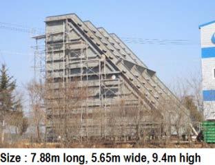

4 4 Concept design New cargo containment system (KC-1) development employing KOGAS membrane KC-1 : AIP(Principle), DA(Design) 4 Class Approval Patents : Registration (46) CCS Design/Testing Technology acquisition Element Design Mock-up test Basic Design Structural Tests Constructability Review


")
 NO.")
5 5 LNG Cargo Tank Independent Tank Hull Integrated Tank Type A Type B Type C P 700 mbar Full Secondary Barrier P 700 mbar Partial Secondary Barrier P 2000 mbar No Secondary Barrier Membrane P 700 mbar Full Secondary Barrier Prismatic Prismatic (SPB) Cylindrical KC-1 (KC) Mark III (GTT) NO.96 (GTT) Spherical (MOSS) Bilobe
6 CONTENTS 1. Introduction II. Design Concept of KC-1 III. Summary
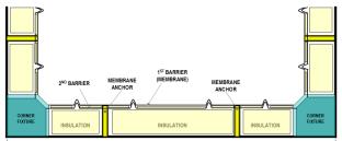
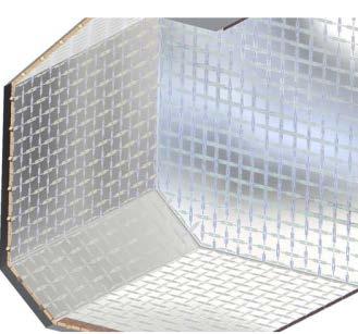
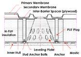
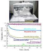
7 7 Basic Principles of KC-1 System Basics : The primary and secondary membrane are made of non-continuous, corrugated SUS 304L, 1.5mm thickness. They are fixed to the membrane anchor and supported by the insulation system Characteristics : In order to enhance gas leak proof condition, the KC-1 has double metal barriers No thermal shock at the secondary barrier in the case of LNG leakage of primary barrier Minimization of effects on the insulation system from hull deformation as the insulation is not bonded to the hull Easy to manufacture and install due to employment of one layer of insulation panel No weld on the membrane corrugations at site

8 8 Main-Structure of KC-1 System Primary Barrier Secondary Barrier System Characteristics Primary Barrier Barrier - Primary and Secondary barrier with corrugation - Secondary barrier is located near primary barrier One layered insulation KOGAS Membrane type 1.5mm SUS304L Same corrugation size on plane No cross corrugation Corner Anchor Inter-Barrier Spacer Secondary Barrier Verified Safety using the structure identical to primary barrier 1.5mm SUS304L Corrugation No need to reinforce Membrane Anchor Insulation

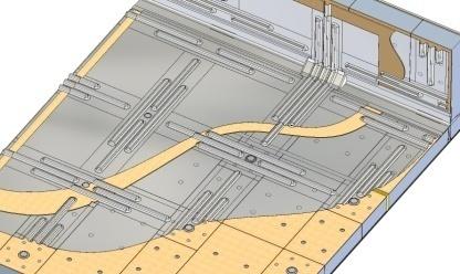
9 Typical Configuration of KC-1 System 9


10 10 Features of KC-1 Membrane 3Non-continuous 중의단속주름이and 지그재그로 Arch-shaped 배치된end 형상으로 corrugations 프레스금형가공에의하여제작됨. 현장 Grid shape 주름부formed 용접을 by 없앰으로써 corrugations 용접품질 is rectangular 개선을통한 as shown 생산성below 향상도모. To improve reliability of tightness, the membrane is non-continuous corrugated type with three lanes applied with flat welding joint at site No welding points on corrugations (a) Mark-III membrane (b) KC-1 membrane

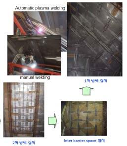
11 11 Membrane Panel 멤브레인 Membrane 설치를 panel 위한 consists 기본단위로 of membrane 멤브레인sheet 시트와 and 평판을 flat sheet 프라즈마맞대기용접 (Plasma Arc Welding, PAW) 으로제작 Manufactured by using automatic Plasma Arc Welding 품질검사는치수및용접부의 Visual test 및 DPT를수행 Visual test, and DPT on welding points and checking dimensions are conducted in process of quality control

12 12 Duration reduction : Transfer and install the membrane panel automatically Work flow : supply membrane membrane installation return carrier Available in overhead, vertical and horizontal installation Membrane installation Membrane Carrier Longitudinal Rail Supply Membrane Return Carrier Moving Rail Fig. Membrane Installation Work flow


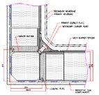
13 13 Corner Fixture Corner fixture consists of wing plate and base plate Wing plate is designed to withstand only tensile load Base plate is fixed to inner hull using bolts Compressive load due to liquid pressure and sloshing load have no effect on wing plate Wing plate Base plate


14 14 Thick Plate It is composed of two plates and connected to membrane by welding The thick plate has function as the primary and secondary barrier at corner parts. The thick plate can be sliding in longitudinal direction The thick plate is fastened to holder using bolt Moving Rib Corner Fixture Fixing Rib Moving Rib


15 15 Membrane anchor is used to fixation parts of membrane in the insulation panels Location : inside insulation panel Membrane anchor is assembled with insulation panel at fabrication shop Membrane anchor can be sliding in horizontal direction Membrane anchor is fixed in vertical upward direction and free in downward direction


 and Corner Panel(CP) (a) Flat Panel(FP) (b)")
16 16 Insulation Panel(=IP) is a bonded sandwich structure with an only one layer including back plywood, rigid closed cell foam panel and top plywood Uses PUF insulation instead of R-PUF Excellent thermal isolation (thermal conductivity approx. 10% lowers) Insulation panels are easy to manufacture Use of environmentally friendly, high-performance insulation (blowing agent : HFC-245fa) Insulation panel is generally divided by Flat Panel(FP) and Corner Panel(CP) (a) Flat Panel(FP) (b) Corner Panel(CP)

17 17 Main function of the IBS is that the damage on primary membrane should not have an influence on the secondary membrane by maintaining regular distance Male fixing cap Female fixing cap spot welded at shop Secondary membrane The female fixing cap is spot welded on secondary membrane and inspected at fabrication shop Improving the reliability of secondary membrane Put in the male fixing cap after installation of IBS at a shipyard Female fixing cap Inter barrier spacer Male Fixing cap at fabrication shop At the shipyard

 Pump Tower be welded to")
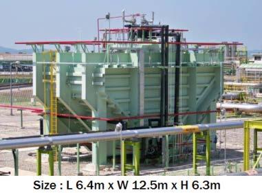
18 18 Design : Rectangular shaped structure (2 Pump columns, 1 Emergency column, 1 Filling nozzle) Pump Tower be welded to Liquid dome cover


19 19 Two bottom support for fixing the horizontal movement and rotation Support 1 : Fixed in the horizontal direction Support 2 : Control the rotational behavior Support 1 Support 2
20 CONTENTS 1. Introduction II. Design Concept of KC-1 III. Summary
 NO 96 (GTT) KC-1 Membrane Material SUS304L (1.")
 Size 1,020mm 3,060mm 500mm(B) Tank Length")
 PUF Thickness (Typ.")
21 21 <Mark-III> <NO 96> <KC-1> Description Mark-III (GTT) NO 96 (GTT) KC-1 Membrane Material SUS304L (1.2mm) 36% Ni Steel (0.7mm) SUS304L (1.5mm) Size 1,020mm 3,060mm 500mm(B) Tank Length 3,700mm 7,600mm Insulation Panel Material R-PUF Plywood + Perlite (NO 96) PUF Thickness (Typ.) 270mm ( ) 530mm ( ) 270mm

22 22 Unique containment system using closed double metal barriers Enhance gas leak proof condition at primary and secondary barrier No thermal shock at the secondary barrier even in the case of LNG leakage Duration reduction : Transfer and install the membrane panel with the help of MSS Uses PUF insulation instead of R-PUF excellent thermal isolation (thermal conductivity approx. 10% lowers) Simple insulation system which employs only one layer of insulation Insulation panels are easy to manufacture Reduction of the number of quality control items during construction Enables a short construction term of the containment system (No welds on the corrugation at erection stage, using the facilitation of large capacity etc.)


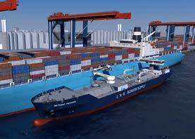
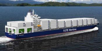
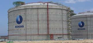


23 23 FLNG FSRU SSLNG LNG Fueled Ship Land Storage Tank Bunkering Vessel
24 Thank you for your attention!