AGA Roof Deck Pavers. AGA Concrete Paver. Technical. Pavers: Hydraulically pressed concrete pavers: 460 tons of pressure.
|
|
|
- Lucinda Williams
- 5 years ago
- Views:
Transcription
1 Cut Sheet AGA Roof Deck Pavers AGA Concrete Paver Overview: AGA Standard sized pavers are manufactured to meet project requirements. Custom: we offer a variety of custom sizes and a mixture of colors and finishes to meet any specification over and above the finishes listed below. Our concrete pavers have the density and strength of stone using a hydraulic European press eliminating excess water and air from the wet concrete mix. Precision molds are used to ensure uniform size and texture of each paver. Technical Pavers: Hydraulically pressed concrete pavers: 460 tons of pressure. Form Materials: Precision molds. Concrete Mix: Minimum compressive strength: 8,500 pounds per square inch* (psi): (58,605 kpa) Density: 150 pounds per cubic foot. Water absorption rate: < 5% Sizes: Standard: Pavers are nominal 23-1/2 x 23-1/2 and nominal 17-5/8 x 17-5/8 by 2 in thickness. Custom as required. Finishes: AGA Natural Color Water Absorption: < 5% (five percent) Standard Pedestals: Standard pedestals as required per project specification.

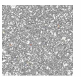
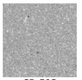
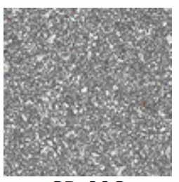
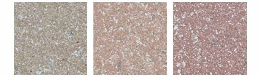
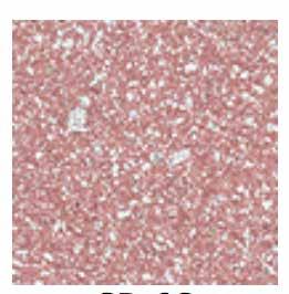
2 Standard Natural Color Standard Architectural Colors


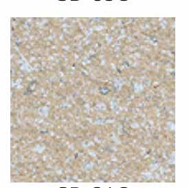
3 Custom Colors / Aggregates We offer a variety of custom sizes and a mixture of colors and finishes to meet any specification over and above the finishes listed below
4 AGA Paver & Pedestal Standard Installation Preparation Prior to installation it is important to determine variables in the roof system that will affect the paver and pedestal system. Structural Capacities: The live-load and compressive load factors of the substrate must be determined prior to installation of any paver and pedestal system. Membrane Compatibility: There are variables to consider based upon the membrane type being used on the roof. Some membranes are subject to softening at high ambient temperatures. In some cases, a protection board or membrane insulation may be required under the pedestal to decrease point load pressure on the membrane. Disclaimer: Consult with membrane manufacturer, insulation manufacturer and AGA for questions concerning compatibility between membrane and pedestal prior to installation. Roof Parameters: It may be necessary to use ballast on the roof deck perimeter and around protrusions where it is not practical to cut pavers to fit (i.e. canted roof-wall junctures). Pedestal Requirements: Determine the number of pedestals required. Columns and other protrusions, where pavers are cut and fit, will increase number of pedestals required.
5 Installation The following information provides specific detail for installation of the paver and pedestal system. Installations are completed based upon architectural drawings provided for each project. As such, the installation process may vary to achieve the correct installation. PART 3 EXECUTION EXAMINATION A. Prior to starting work, carefully inspect installed work of other trades and verify that such work is complete to the point where work of this Section may properly commence. Notify the Architect in writing of conditions detrimental to the proper and timely completion of the work. B. Do not begin installation until all unsatisfactory conditions are resolved. Beginning work constitutes acceptance of site conditions and responsibility for defective installation caused by prior observable conditions. C. Verify that substrates, membranes, and protection boards are ready for installation of pedestal system, and pavers. 1. The substrate that is to receive pedestals shall have positive slope to provide adequate drainage in accordance with good building practices. 2. Inspect to insure that all substrates have been properly prepared to accept the pedestals. Any surface defect which may impair performance of the pedestals or waterproofing membrane shall be appropriately repaired. Commencement of work shall imply acceptance of surfaces. 3.2 PREPARATION A. Establish accurate lines, levels, and pattern. B. Assure that the surface to accept the pedestals is clean and free of debris which would impair the performance of the pedestal system. C. Insulation and/or protection board may be applied over the waterproofing/roofing substrate. If specified, drainage mat, insulation and/ or protection board must be installed according to manufacturer s recommendations. If protection is specified only under the pedestal, then each pad must extend beyond the edge of the Pedestal System bottom cap or Buffer Pad, by a minimum of 2-inches.
6 3.3 PEDESTAL SYSTEM INSTALLATION A. GRID LAYOUT AND ELEVATIONS 1. Layout the paver and pedestal grid layout, starting point and finished elevations in accordance with approved shop drawings which have been reviewed by the A/E or Designer, installing Contractor and Owner s Representative. B. LEVEL INSTALLATION 1. Establish starting point and finished elevation of the paver surface, the support system elevation (finished elevation less the paver thickness) is established and marked around the perimeter using transit, water level or laser leveling device. 2. Take measurements, and provide two (2) perpendicular chalkline snapped on the surface to receive the pedestals. Use these lines as a reference to check the paver layout during installation and to assure a square layout. Installation of paver can now begin, one row at a time. 3. At the starting row of pavers, a pedestal must be placed where each grid line meets the perimeter. Remove two spacer tabs in line with one another from atop each Pedestal System top cap, located along the perimeter. Adjust each to the elevation marked on the perimeter. 4. Position the pedestal as close to the edge of the perimeter as possible, with the two remaining spacer tabs aligned with the grid line. Using the elevation marked on the perimeter, stretch a mason s line along and slightly ahead of the second row of pedestals. A laser leveling device may also be used for this purpose. 5. Top Shims: Slight irregularities in paver thickness and/or deck heights, can be compensated for by using one or more of four pie-cut segments of Top Shims which is placed under a paver corner(s) atop the Top Cap at intersection quadrants. 6. Bottom Shims: Slight irregularities in paver thickness and/or deck heights (with additional slope requirements), can be compensated for by using one or more of the Bottom Shims which is placed below the Bottom Cap. 7. Buffer Pads and Protection Board: Install Buffer Pads and 12 x 12 x 3/8 thick protection board below each Bottom Cap of the pedestal assembly, when installing the Pedestal System over: a) Built-Up roofing (BUR) membranes that are installed over rigid or semi-rigid insulation; b) Elastomeric type waterproof and/or roofing membrane coatings, so as to prevent damage to the membrane or coating system;
7 C. SLOPED INSTALLATION 1. Compensation to maintain a level paver surface over sloping substrates, can be accomplished using a combination of the following: a) PVC Pipe length cut to varying lengths to compensate for slope; b) Bottom Shims: Place one or more Bottom Shims under the Bottom Cap, to compensate for up to 1 inch per foot of slope. c) Top Shims: Place the Top Shims (pie-shaped pieces) on to the Top Cap, in increments of 1/16 inch to precisely level the top on substrates with slope of up to 5/8 inch per foot. D. PERIMETER CONTAINMENT 1. Any section of paver, pedestal or protection course which is not restrained by an abutting wall or parapet must be boxed in by some field installed restraint. No movement should be allowed at the perimeter of a paver system greater than 1/8 of an inch. 3.4 PAVER INSTALLATION A. Install pavers in accordance with paver manufacturer s written instructions. Carefully align the Top Cap joint spacers with paver edges. Level pavers in each succeeding row. B. Install pavers tightly butted into pedestals. Form minimum joint widths. C. Shim or adjust to level and as necessary to prevent rocking of pavers. D. Installation Tolerances: 1. Step in Face Alignment Between Paver Faces: Plus or minus 1/16 inch. 2. Jog in Joint Alignment Between Paver Sections: Maximum 1/16 inch. E. Do not use pavers with chips, cracks, voids, stains, or other defects which might be exposed to view in the finished work. 3.5 FIELD QUALITY CONTROL A. Continuing and Final Inspection: Inspect often during installation to assure that grid (spacer) lines are straight and consistent, and that pavers are level, and where necessary, install Top or Bottom Shims; confirm that heights in excess of fifteen (15) inches have been braced in accordance with Tile Tech Pavers written instructions. 3.6 CLEANING A. Clean soiled surfaces using solution which will not harm concrete pavers. Consult paver supplier for recommended type. B. Use non-metallic tools in cleaning operations.