CONTENT. INTrOduCTION 3. units & CONNECTOrs 4. standard INsTallaTION PrOCEdurEs 5
|
|
|
- Brett French
- 5 years ago
- Views:
Transcription
1
 8 MEsa CurvEs & COrNErs 9 MEsa design CHarTs")
2 CONTENT INTrOduCTION 3 units & CONNECTOrs 4 standard INsTallaTION PrOCEdurEs 5 step 1 - Preconstruction Preparation 5 step 2 - Prepare the leveling Pad 5 step 3 - Install the Base Course 5 step 4 - Geogrid and Connector Placement 7 step 5 - Place and Compact Backfill 7 step 6 - Install additional Courses 8 step 7 - Place Cap units (When required) 8 MEsa CurvEs & COrNErs 9 MEsa design CHarTs 11
3 3 INTrOduCTION The Mesa retaining Wall systems offer superior and costeffective solutions for all of your retaining wall needs. This installation guide provides general instructions to assist in the construction of Mesa retaining Walls in a wide variety of applications. The Connection You Can Count On unlike other segmental retaining wall (srw) systems, Mesa Walls incorporate a positive, mechanical connection between the wall face and the Tensar Geogrid reinforcement providing unsurpassed structural integrity. It s this positive, mechanical connection that greatly reduces the chance of wall failure, even under the most severe conditions. Only Mesa Walls provide the aesthetic architects demand, the efficient installation contractors expect and the dependability engineers require all from a single source. Endless Design Options No matter what design considerations are needed, the Mesa systems have a solution. From structural walls to tiered gardens and curved walls to stairs, Mesa Walls blend effortlessly with the natural surroundings of any site. For more information, call your authorized Mesa systems licensee or distributor; contact Bolduc at


) variable")


4 4 units and CONNECTOrs The regular straight or radius-face MEsa blocks, and the straight-faced antique model are available locally. They have been designed for a wide variety of applications. Standard units (8" h x 18" w x 11" d nom. / 75 lbs) Antique cap units (use appalachian coping for antique-finish Mesa walls) straight face radius face Antique units (8" h x variable wide (see below) x 11" d nom. / kg (see below)) variable dimension: a: 18" / 88 lbs B: 11" / 60 lbs C: 7" / 42 lbs Standard connectors a straight face B C Cap units (4" h x 18" w x 11" d nom. / 40 lbs) Tensar Uniaxial (UX) Geogrids straight face radius face
5 5 standard INsTallaTION Pr0CEdurEs The following steps provide general guidelines for installing a Mesa Wall. If you require more detailed information, please refer to the Mesa systems Installation and special Considerations Manual or the project s installation instructions and drawings within the contract bid documents. Step 1 : Preconstruction Preparation It s important to make yourself familiar with the components of the Mesa systems prior to the start of construction. Below is a list of these components as well as the tools you will need to construct a standard Mesa Wall. Mesa corner units, drainage composite, piping and geotextile materials may also be required. Suggested tools for installation: dead blow hammer 2- to 4-ft level utility saw and/or grinder Masonry string and chalk line Pitchfork (for removing slack from geogrid) shovels Compaction equipment rubber mallet Step 2 : Prepare the Leveling Pad Prepare the subgrade by excavating vertically to plan elevation and horizontally to design geogrid lengths. If stockpiling excavated material for reinforced fill, remove all surface vegetation and debris in the stockpile area. start the leveling pad at the lowest elevation of the wall. level the prepared base with 6 in. of unreinforced concrete or well-compacted granular fill (gravel, road base or 0-3/4 in). The leveling pad is typically 12 in. wider than the Mesa unit, 6 in. in front and behind the block. The contractor should locate the leveling pad to account for wall curves and wall batter. Compact fill to 95% of the maximum dry density. steps in the leveling pad are required to change elevation. It is important that the height of the step is equal to the height of the number of unit courses. aggregate leveling pads are generally overbuilt and should be carefully trimmed down to meet the proper elevation. If a concrete leveling pad is used, it is important to have the step heights match the Mesa unit s height exactly. If not, grinding and/or shimming may be required. use a thin set masonry mortar to make up for variations or follow the recommendations for shimming between block courses to account for minor variations. (see page 8 to know the suitable shims application). shim pad up to this elevation leveling Pad Grind pad down to this elevation Step 3 : Installation of the first course of blocks and subsequent courses Once the levelling pad is in place, trace or stretch a guideline (11") behind and parallel to where you plan to erect the wall. a chalk line works perfectly with a concrete foundation; a masonry line is better with a compacted aggregate foundation. Install the first course of Mesa blocks next to each other, leaving a little space (1/16-2/16 in.) between each pair. Make sure the textured surface faces outward (Figure 3.1). use the traced or stretched guideline to align the rear of the blocks. The first course must be perfectly aligned with the guideline and the Mesa blocks levelled and slightly spaced. This will greatly facilitate the building of the wall. It is possible that for a block may not be the same height as the others. In such a case, use a shim to adjust block levels. We recommend the procedure illustrated in Figure 3.2 for Mesa antique blocks.

 must be strictly adhered to.")

6 6 The recommanded installation is to work with a specific module made of the three regular blocks installed in the sequence large #6 small #8 - Medium #7 as illustrated in Figure 3.3. repeat this coordination to install the first course of blocks. The given positioning sequence (large #6 small #8 - Medium #7) must be strictly adhered to. repeat the sequence for all odd-numbered (3rd, 5th, etc.) courses. Figure 3.1: Installation of first course on levelling pad. Figure 3.2: layout procedure for antique Mesa modules Basic Module starting Module1 Complementary modula- starting Module 2 Figure 3.3: description of modules for antique Mesa installation
 connectors are used per block.")


7 7 Step 4 : Geogrid and Connector Placement Prior to placing additional courses, two Mesa Connectors are inserted into each preceding Mesa unit. For regular straight or radius-face units, two (2) connectors are used per block. For Mesa antique blocks, the large and medium modules require two (2) connectors whereas the small module only requires one (1). The flags or exposed portion of the connector orientation will create the batter of the wall face. 5/8" setback Once the connectors and the geogrid are in place, the Mesa units must be swept clean prior to placing the next course. Failure to do this can result in problems with seating and leveling of subsequent courses. The "anchored" geogrid can be turned back toward the wall face when spreading fill up to Front face of the wall Near vertical If the design dictates the need for a geogrid at a particular elevation, the Tensar Geogrid will be installed with the teeth of the Mesa Connectors penetrating through the geogrid apertures. The flags should never be utilized to connect the geogrid to the facing units. Mesa connector without setback. Transverse Bar Mesa connector with setback. the geogrid's level. Step 5 : Place and Compact Backfill Install drainage fill, typically 3/4 in. well-graded stone, behind the wall face as directed by the design drawings (12 in. min.). Peagravel should not be used for drainage fill. Behind the drainage fill, use backfill material that meets project specifications. When placing backfill over the geogrid layer, the fill should be placed to minimize any slack in the geogrid. Placing the fill in a direction away from of parallel to the face of the wall will minimize this slack. In addition to the direction of fill placement, a pitchfork can be used to remove slack. Typically, loose lifts of the reinforced fill shall not exceed 6 in. where hand-operated compaction equipment is used. These thicknesses may vary depending on the approved project-specific soil types used. Compact fill to 95% of the maximum dry density as determined in accordance with astm d-698 (standard Effort Proctor Test). snug the geogrid against the connector teeth, and then drive the connector the rest of the way using a rubber mallet. Note : The transverse bar of the geogrid must be pulled taut against the teeth of the connectors prior to final seating of the connector into the block. any slack in the geogrid may be removed by anchoring it with stakes or sebar.
8 8 Note : Only hand-operated compaction equipment shall be used within 3 ft of the tail of the Mesa units. Step 6 : Install Additional Courses Regular Mesa Place the next course over the Mesa Connectors on the previous course, fitting the flags inside the open cavity of the block. Push the unit forward, so that it makes contact with the connectors. The vertical joint alignment should be checked frequently as the connectors allow the units to slide from sideto-side. as you build up, maintain level on each course by continually checking for level front-toback and side-to-side. If needed, shim when required. Once the current course is level, continue to repeat steps 4 through 6 until final elevation is reached. Antique Mesa When placing the next course of blocks, make sure the continuous groove on their underside is placed above the connectors of the course below. Pull the blocks toward the front so that they come into contact with the connectors. small units (#8) may require moving a large block's (#6) connector toward the central position. When installing the second course, as well as all even-numbered courses (2nd, 4th, etc.), use a special course-starting module comprising 2 identical blocks. use two medium #7 blocks for starting Module #1 or two small #8 blocks for starting Module #2. Follow these modules with the three-block Basic Module (large #6- small #8-Medium #7), as described in the installation of the first course of blocks. If possible, complete the wall s last course with various blocks as illustrated for the complementary modulations. Each start modulation has a corresponding complementary modulation that balances the various modules and makes optimal use of the ratio of blocks on the palette. concrete to concrete should be used to secure cap units to the course below. The adhesive should be suitable for use in an outdoor environment and stable under the temperature extremes expected for the local area. apply the adhesive in accordance with the adhesive manufacturer s recommendations. Shimming Mesa Units It is important that the courses of Mesa Blocks are level front-to-back and side-to-side. It may be necessary to grind the blocks or use shims between some of the courses to correct an out of level condition.the shim material can be a transverse bar trimmed from the same roll of Tensar Geogrid. Step 7 : Place Cap Units (When Required) These units may be placed such that a nominal 1 in. overhang is achieved or flush with the face of the wall. a concrete adhesive suitable for bonding


9 9 MEsa CurvEs and COrNErs Concave Curves When possible, begin a concave wall from the center of the curve, alternating left and right of the center unit. When building with a 5/8 in. setback, each Mesa unit falls behind on a concave curve relative to any units below. It is suggested that a flex pipe be placed on the tail of the units in the curve to ensure a smooth curve. If using the 5/8 in. setback, overlap corners of the Mesa units on the base course. The amount of overlap will vary based on the size of the curve. The radius becomes larger as the wall becomes taller, therefore gapping will occur. The maximum acceptable gap is a 1/8 in. If the maximum gap is exceeded, one flag may be removed from each connector to close the gap. diagram a Table 7.1 shows the maximum height for the targeted radius of curvature while respecting the 1 maximum joint space. diagram a NOTE : On tight curves, Tensar Geogrid may be cut lengthwise to the width of the Mesa units to ensure the transverse bar engages both connectors. The wall designer should consider eliminating the requirement for fill between overlapping layers in areas with a tight radius and/or staggering the layout of adjacent sections of geogrids. NOTE : On tight curves, Tensar Geogrid may be cut lengthwise to the width of the Mesa units to ensure the transverse bar engages both connectors. Convex Curves as with concave walls, begin a convex wall from the center of the curve alternating left and right of the center unit. It is suggested that a flex pipe be placed on the tail of the units in the curve to ensure a smooth curve. radius of curvature at the base of the wall (ft) (m) Maximum height (ft) with 1 in. spacing between first course blocks Table 7.1 Convex curve: Maximum height as a function of wall s radius of curvature 8 When a 5/8 setback is used, make sure you use the proper spacing between the blocks in the first course. as opposed to concave radius, each additional course shrinks convex radius.


10 10 90 Outside Corners First Course drainage fill shall be placed in the core of the corner unit and in the core of the units to either side of the corner unit. diagram a Second Course For Mesa walls built with the regular modules and a 3/4 setback, cut the smaller side of the corner block on location to take the setback into account and maintain a continuous connection. It is not necessary to perform this adjustment with Mesa antique units. alternate the orientation of the corner block and align it with the center line of the first course blocks. use an approved outdoor concrete adhesive to affix the corner block to the underlying unit. Clean gravel should be placed in the corner block s central cavity and in the adjacent blocks on either side. diagram B diagram C

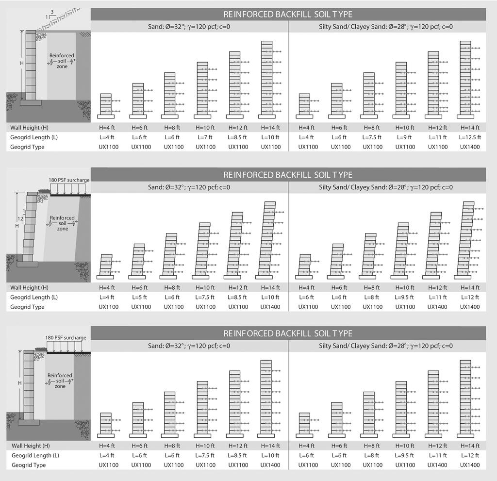
11 MEsa design CHarTs 11
12 12
13 NOTEs
14 NOTEs
15 NOTEs
 G6E 1G8 sainte-marie : 418 387-2634")

16 Concrete product manufacturer 1358, 2 nd street (Industrial Park) sainte-marie, Beauce (Quebec) G6E 1G8 sainte-marie : Canada: usa : Fax : info@bolduc.us Imprimé au Canada Zl1-EN15-INsTalMEsa