CO2CRC Otway Stage 3 Project
|
|
|
- Elvin Webb
- 5 years ago
- Views:
Transcription


1 CO2CRC Otway Stage 3 Project Project Summary Dr Maxwell Watson Program Manager - Storage CO2CRC Ltd CSLF Projects Interaction and Review Team 3 rd December 2017, Abu Dhabi, UAE

2 Presentation Outline CO2CRC and its Otway Research Facility CSLF Recognised Otway Stage 2 Update Basis of Stage 3 Subsurface Based Monitoring Solutions Stage 3 Monitoring technologies Otway Validation Anticipated Outcomes from the Otway Stage 3 Project 2


3 Otway Research Facility - Location CRC-6 CRC-7 CRC-4 CRC-2 CRC-1 Naylor-1 Visitor Centre CRC-5 CRC-3 3

4 Otway Research Facility CCS Demonstration and Technical Validation Otway Stage 1: Demonstrated safe transport, injection and storage of CO 2 into a depleted gas reservoir Otway Stage 2: Demonstrate safe injection of CO 2 into a saline formation Stage 2B Validate near well residual & solution trapping characterisation Stage 2C Minimum detection, 4D M&V & Plume stabilisation Otway Stage 3: Demonstrate safe, reliable and cost-effective subsurface monitoring of CO 2 Other Projects Otway Shallow Fault Characterisation Otway CO 2 Capture Skid 4


5 CSLF Recognised Otway Stage 2 Update 5 Kt 10 Kt 15 Kt 15 Kt 1 yr post injection 5 5
6 Otway Stage 2: Conformance and Stabilisation Workflow With a small, short-term empirical trial (Otway), a generic and validated workflow for conforming long term plume predictions (including stabilisation) to early monitoring observations will be developed End of injection ~500 m Up dip Year 2 Year 1 Otway conformance & stabilisation demonstration: ~10,000s t, < 3 years Up dip ~10s of km Year ~500 Year ~40 Year ~100 Year ~1000 Year 1 Year 10 End of Injection Commercial project ~10s of Mt, >100s years 6
7 Otway Stage 3: Challenge Statement Lengthy monitoring (decades) of storage sites may be required by regulators in many jurisdictions This poses issues of cost, extended liability and social license Conventional 4D seismic Relatively high cost compared to other geophysical or remote sensing techniques Significant time delay between data acquisition and availability of interpreted results Sparseness in sampling of the temporal changes in the subsurface Relatively high level of invasiveness, particularly for multiple surveys Relatively low sensitivity for TL due to poor repeatability Depth limited, geology limited Other techniques Pressure monitoring is under-utilised Generally whole plume M&V, yet low resolution associated with key leakage mechanisms Gold plating, where additional M&V may not add significant value M&V poor reliability, difficult to operate 7


8 Stage 3 CO 2 Storage Management & Subsurface Monitoring &Verification 1. We will develop a high-resolution, real-time monitoring capability. The technologies will provide an early warning solution for industry and regulators. 2. We will provide non-invasive monitoring techniques that will be acceptable for community and regulators. 3. The project will provide a prospectus of technologies and workflows that can be used to define costs in commercial monitoring projects. 4. The project will evolve technology from benchtop application to in-field validation, which is being driven by current and prospective operator need. 8
9 Stage 3 Monitoring Technology Selection Risk Targeted Fit-for- Purpose Unique / Innovative / Novel Cost Effective Commer cial pathway Stage 3 Core Objectives Ease of Operation Value of Infomation Regulatory Regime Low Impact Opportunity Definition Down-select Evaluate Core M&V Feasibility Define Core vs noncore M&V Added opportunities Non-core M&V 9
 and Pressure Tomography (active) Automated, Multi-well Time-Lapse (TL)")

 or at-scale CO 2")
10 The Monitoring Concept Two primary monitoring modalities with numerous monitoring applications Pressure Inversion (passive) and Pressure Tomography (active) Automated, Multi-well Time-Lapse (TL) Vertical Seismic Profiling (VSP) Backup by ground truth from convention 4D seismic and/or 4D VSP Subsurface monitoring configuration must achieve Variety of monitoring paths across plume at various stages of injection Sufficient signal-to-noise ratio for plume detection Validated against an at-scale CO 2 plume leakage proxy in an Above Zone Monitoring Interval (AZMI) or at-scale CO 2 plume edge 10

 Pressure Inversion: targeted to regional scale location of subtle leakage events passively, in a continuous monitoring sense.")

11 Pressure Monitoring (Inversion and Tomography) High resolution/accuracy, commercial pressure gauges, are commonly deployed in injection and monitoring wells Can provide continual, automated monitoring over 100s to 1000s metres. Emerging interpretation techniques enable location and attribution of a change (pressure inversion) and rough visualization of a plume (pressure tomography) Pressure Inversion: targeted to regional scale location of subtle leakage events passively, in a continuous monitoring sense. Compressibility Monitoring: passive, change in average reservoir compressibility detected by analysing response to earth tides, for CO 2 plume detection in advance of arrival Pressure Tomography: active, multi-well pressure monitoring technique that is used as a low cost alternative approach to monitor CO 2 distribution, with minimal acquisition operation. 11
 and DAS as a receiver for continuous updates of plume migration (including automated processing).")

12 Seismic Monitoring (Permanent Down Hole Active & Passive) Downhole-based seismic using modern cost-effective technical solutions: Automated multi-well Time Lapse Vertical Seismic Profiling with permanent sources (Stationary Orbital Vibrators) and DAS as a receiver for continuous updates of plume migration (including automated processing). Cross-hole seismic to improve vertical and lateral resolution focus Microseismic monitoring to track pressure front propagation. Changing conventional geophones to optical fibre lowers cost and increases longevity of seismic monitoring installation Undertaken with remotely-operated, continuous acquisition provides and automated interpretation Verification monitoring: 4D surface seismic acquired with buried array 4D multi-well VSP using re-deployable source (both DAS and geophones) 12
13 M&V Technology Comparison Core M&V Technologies Pressure Tomography & Pressure Inversion Multi-well 4D VSP w. DAS & SOVs Options for Define Earth tides (Compressibility M&V) Microseismic X-well Seismic Casing Emag Geochem DTS (well integrity) Project Project Status In-zone pressur e PTI Earth tides 4D seismic 4D VSP Abovezone pressure Multiwell 4D VSP Emag (various) Otway Stage 3 Proposed X X X X X X X TBD Peterhead/Goldeneye Proposed X X X X FutureGen Proposed X X Quest Active X X X X Illinois Basin-Decatur Active X X X Bell Creek (US regional Active X X X X ~X Partnerships) Citronelle (US regional Partnerships) Cranfield (US regional Partnerships) (completed) Farnsworth (US regional Partnerships) Michigan Pinnacle Reefs (US regional Partnerships) Completed X X X Completed X X ~X X X X Active X X X Active X X Aquistore Active X X X ~X X Weyburn Active X X X Ketzin Completed X X X X In Salah Completed X X Sleipner Active X Snovit Active X X Nagaoka Completed X X Tomakomai Active X X K12-B Completed X 13 Casing Emag

 15,000 40,000")

14 Subsurface Monitoring Concept Validation at Otway CRC-3 CRC-2 CRC-6 CRC-7 1 new injector (CRC-3) and 4 new monitoring wells (CRC-4 to CRC-7) 15,000 40,000 tonnes injection (Buttress-1 Gas) Pressure & Seismic-based M&V of migration up-dip to Stage 2C plume 14

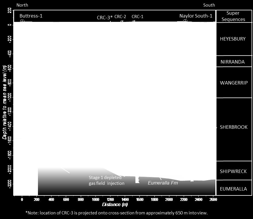
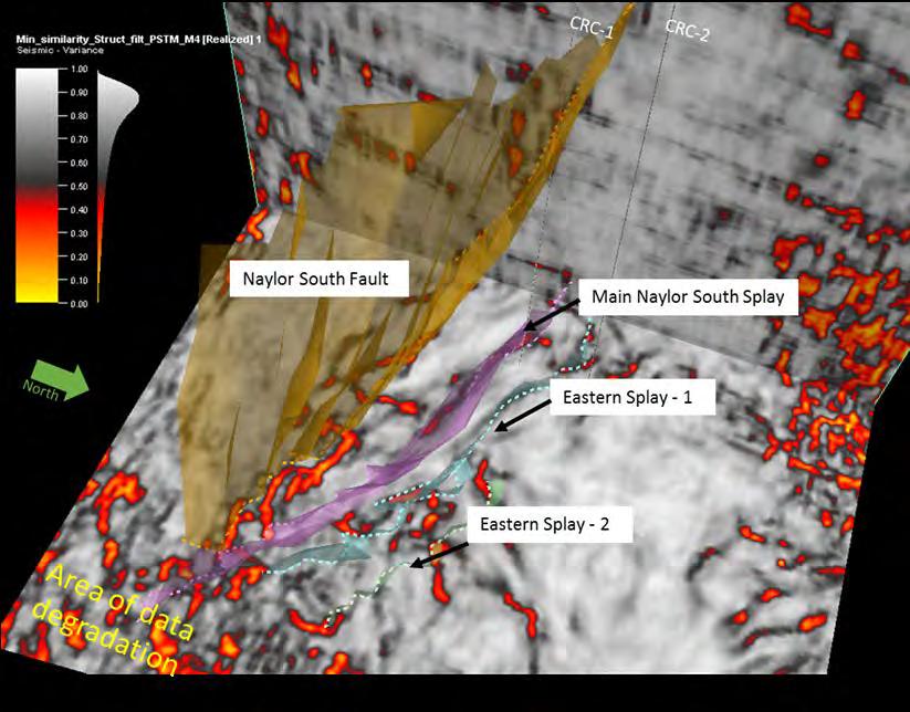
15 Geological Characterisation Confirm Structural/stratigraphic tops Facies heterogeneity Reservoir quality Hydraulic continuity 15
16 CO 2 Plume Migration Top view of the Stage 2C saturation plume on Jan 1, 2018, at the end of Stage 2C injection. Saturation cut off is 5%. Top view of the saturation plume on May 10, 2018, at the end of Stage 3 injection. Stage 3 injection is on the left and stage 2C injection is on the right. Saturation cut off is 5%. 16
17 Plume Migration Top view of the Stage 2C saturation plume on May 10, 2019, five years after the Stage 3 injection. Saturation cut off is 5%. Top view of the Stage 2C saturation plume on May 10, 2020, 10 years after the Stage 3 injection. Saturation cut off is 5%. 17


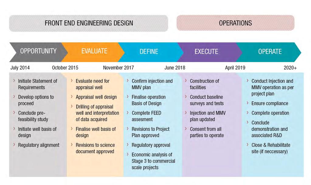
18 Project Timeline & Breakdown 18

19 Evaluate Phase: Reducing Uncertainty Appraisal (CRC 3) Well Operations Rig operations lasted 30 days Well was drilled to 1,667m depth Executed FE Plan and gathered high quality dataset Captured detailed lessons learnt Maintained social licence to operate Provided a pathway forward for Stage 3 Achieved success in challenging wellbore operations 19

20 Stage 3 Basis Of Design Surface Facilities Deviated Wells Two affected landowners Single new drillpad & 300m access road, to access CRC- 6 & 7 Re-utilisation of Naylor-1 drillpad Power & Communications to only two sites SOV s would need to be positioned stand-alone above targets and connected with power and comm s via shallow HDD 20
21 Stage 3 Outcomes and Parameters Proposed Outcomes from Stage 3 Subsurface seismic monitoring solution: This subsurface monitoring solution will partly to fully substitute the need for on-going repeat surface seismic acquisition thus saving significant operational costs, and present improved Pressure monitoring: Greatly expanded range of investigation and monitoring capabilities through novel uses of pressure monitoring, at far lower costs than other monitoring modalities; Risk Targeted: M&V approach is applicable in testing whether local thresholds/limits are approached/exceeded, and that risk events, if occurred, is detected quickly. This is particularly important where reservoir utilisation optimization is critical. Transferability of research: Ensure outcomes of research program are scalable as cost saving techniques to commercial CO 2 storage sites and learnings from Otway s onshore M&V activities are transferable to other onshore sites and the offshore environment; Regulatory regime: Develop technologies and practices that provide confidence to regulators and provide operators with effective means to reduce the cost of achieving regulatory compliance and managing storage risk. Overarching Parameters Cost Broadly that the monitoring modalities validated in Stage 3 will present significant saving to commercial scale CO 2 storage projects Effectiveness Broadly that the monitoring modalities validated in Stage 3 will present effective, transferrable alternate solutions to surface-based monitoring Regulatory Regime Demonstrated, comparative technology with low, manageable risk, so that approving authority to be satisfied with the monitoring methodology Social Licence to Operate That the low impact, remote operation in subsurface monitoring solution allows ease of approval locally, and addresses needs, concerns and expectations of the wider public, including from an environmental, sociopolitical, economic and governance perspective 21

22 Further insights Real time storage operation management Capabilities of DCA to improve understanding of heterogeneity 4D Full Wave Inversion Across fault flow modelling monitoring capabilities Dual plume interaction Growing Otway data set Likely more stemming from Define s added opportunity analysis 22


23 Government, Industry and Research Partners 23