Brushy Creek Municipal Utility District
|
|
|
- Carol Walker
- 5 years ago
- Views:
Transcription

1
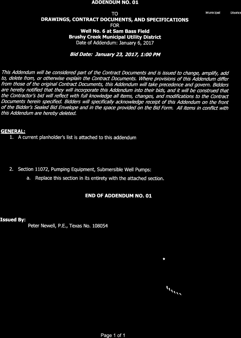
2 Brushy Creek Municipal Utility District Type Company Name Contact Person Address City, State Zip Code Phone Number Project Owner Brushy Creek MUD Joey Miller 1 Great Oaks Dr Round Rock, TX 1 () -1 x0 Engineer HDR Engineering, Inc. Peter Newell, P.E. 01 West Gate Blvd., Suite 00 Austin, TX () -0 Planhouse Virtual Builder's Exchange Erica Draper 0 Naco Perrin, Suite 0 San Antonio, TX () 1-1 Planhouse Amtek John Rugh 01 North Lamar Austin, TX () -00 Contractor Alsay, Inc. Steve Bell Southeast Loop San Antonio, TX () -0 Contractor Associated Drilling Co. Gail PO Box / W. Hwy Dripping Springs, TX () - Contractor Central Texas Water Maintenance, LLC Amy Gray PO Box Buda, TX () -1 $ per set of half-size plans/specs Checks payable to HDR Engineering, Inc. Engineer's Estimate: ~$,.00 Engineer: Peter Newell, P.E. Addendum #1 issued Bid Date: Jan.,, 1:00 BCMUD, 1 Great Oaks Drive, Round Rock, TX 1 Non-Mandatory Pre-Bid Meeting Jan.,, 1:00 PM 1// : PM
3 SECTION PART 1 - GENERAL 1.1 SUMMARY A. Section Includes: 1. Vertical turbine pumps. B. Related Sections include but are not necessarily limited to: 1. Division 00 - Bidding Requirements, Contract Forms, and Conditions of the Contract.. Division 01 - General Requirements.. Section 10 - Equipment: Basic Requirements.. Section 10 - Pump Equipment: Basic Requirements.. Section 00 Pipe and Pipe Fittings: Basic Requirements.. Section 1 Gate Valves.. Section Check Valves.. Section 1 Miscellaneous Valves and Accessories. 1. QUALITY ASSURANCE A. Referenced Standards: 1. American Iron and Steel Institute (AISI).. American National Standard Institute (ANSI): a. B.1, Cast-Iron Pipe Flanges and Flanged Fittings, Class,, 0, and 00. b. B., Pipe Flanges and Flanged Fittings.. ASTM International (ASTM): a. A, Standard Specification for Gray Iron Castings. b. A, Standard Specification for Pipe, Steel, Black and Hot-Dipped, Zinc-Coated Welded and Seamless. c. A, Standard Specification for Steel Bars, Carbon, Cold Finished, Standard Quality. d. Steel, Black and Hot-Dipped Zinc-Coated (Galvanized) Welded and Seamless for Ordinary Uses. e. A, Standard Specification for Stainless Steel Bars and Shapes. f. B0, Standard Specification for Copper-Base Alloy Continuous Castings. g. B, Standard Specification for Copper Alloy Sand Castings for General Applications.. American Water Works Association (AWWA): a. E1, Deep Well Vertical Turbine Pumps - Line Shaft and Submersible Types. National Fire Protection Association (NFPA): a. 0, National Electrical Code (NEC).. National Sanitation Foundation (NSF).. International Organization for Standardization (ISO): a. ISO 10, Mechanical Vibration Balance Quality Requirements for Rotors in a Constant (Rigid) State. 1. SUBMITTALS A. Shop Drawings: 1. See Specification Section 0 for requirements for the mechanics and administration of the submittal process.. Product technical data including: a. Acknowledgement that products submitted meet requirements of standards referenced. b. Manufacturer's installation instructions. c. Pump: 1) Manufacturer and model. ) Speed. - 1
4 ) Number of stages. ) Component materials. ) Shaft and column size. ) Outside diameter of pump bowls. ) Painting and coatings. d. Motor: 1) Manufacturer and model. ) Rated size (horsepower). ) Type of bearings. ) Efficiency. e. Materials, parts, devices, and accessories. f. Complete performance data and curves: 1) Capacity. ) Head. ) NPSH requirements. ) Brake horsepower requirements. g. Shop Drawings: 1) Fabrication. ) Assembly. ) Installation. ) Type, number, and size of anchor bolts. ) Dimensions. h. Factory Test Report: 1) Submit certified copies of factory test report and receive Engineers approval before shipping equipment. ) Report shall include: a) Test log. b) Description of test piping, equipment and set-up. c) Test procedure. d) Certified performance curve, plotted against capacity: (1) Head. () Brake horsepower. () Efficiency. () Speed. () Net positive suction head required. () Plot curve to be easily read at scales consistent with performance requirements. i. Field Test Reports: 1) Motor test report. ) Vibration test report. B. Contract Closeout Information: 1. Operation and Maintenance Data: See Specification Section 0 for requirements for the mechanics, administration, and the content of Operation and Maintenance Manual submittals. PART - PRODUCTS.1 ACCEPTABLE MANUFACTURERS A. Subject to compliance with the Contract Documents, the following manufacturers are acceptable: 1. Submersible Vertical Turbine Pumps: a. Christensen. b. Fairbanks Morse. c. Flowserve. -
5 d. Goulds e. Layne Bowler f. Floway g. Peerless h. Grunfos i. Byron Jackson. Motors: a. General Electric. b. Franklin c. Baldor/Reliance Electric d. Teco/Westinghouse e. Nidec/U.S. Motor Pleuger f. Grunfols g. Hitachi B. Specifications are based on Peerless Pump. C. Submit requests for substitution in accordance with Specification Section 00.. MATERIALS A. Intermediate Bowl, Top Bowl and Flange: Ductile Iron ASTM A, Grade 0--. B. Bearings: Bronze, ASTM B. C. Pump Shaft: Stainless steel, ASTM A, Grade. D. Pump Impeller: Bronze, ASTM B. E. Impeller Lock Collet: Stainless Steel ASTM A,Type. F. Suction Case: Ductile Iron ASTM A, Grade 0--. G. Strainer: Stainless steel, ASTM A0, Type. H. Sand Collar, Strainer Interconnector Bearings: Bronze ASTM B. I. Strainer Interconnector, Suction Interconnector: Ductile Iron ASTM A, Grade 0--. J. Pump Motor Coupling: Stainless steel ASTM A, Type. K. Power Cable: Copper with synthetic rubber. L. Power Cable Guard: Stainless steel ASTM A0, Type 0. M. Cable Clamp and Cable Guard: Stainless steel. N. Wear Rings: Bronze, ASTM B, Alloy. O. Surface Plate: Steel ASTM A.. PERFORMANCE AND DESIGN REQUIREMENTS A. Performance Parameters: 1. Submersible Well Pump: a. Primary design conditions: 00 GPM at FT TDH and greater than 0 percent efficiency. b. Maximum Pump speed: 0 rpm. c. Maximum Pump horsepower: 0 HP. d. Minimum shutoff condition: 0 gpm at FT. e. Minimum Column size: IN. f. Minimum Discharge flange: IN. g. Type of discharge head: above ground. h. Bottom of motor assembly: 1) To be determined by Motor Manufacture. -
6 B. Pump/Motor Shroud: To be determined by Motor Manufacture. 1. Diameter as necessary for motor cooling requirements. Coordinate with well casing diameter. C. Provide pumps with increasing head characteristics from design condition to shutoff condition. Provide pumps with net positive suction head requirements (NPSHR) less than the net positive suction head available (NPSHA) at all operating conditions.. ACCESSORIES A. See Sections 10.. COMPONENTS A. General: 1. Furnish units consisting of a vertical turbine bowl assembly, direct connected to a submersible water filled motor.. Weight of revolving parts of pump including unbalanced hydraulic thrust of impeller is carried by thrust bearing in driver.. Make provision at driver shaft for adjusting impeller with reference to bowls.. Pump and motor to be NSF approved for potable water service. B. Column: 1. The column pipe shall be API-L or ASTM A Grade B pipe.. The column pipe shall be furnished in interchangeable sections not exceeding feet in length and shall be connected with extra strong, straight threaded, sleeve type couplings. The pipe threads should be ¾ inch tapered (NPT) threaded.. The couplings shall be designed to provide the required strength, with a safety factor should the pump be lowered and stages added to meet future conditions. C. Pump Bowl: 1. Pump bowl castings shall be free of blowholes, sand holes, and other detrimental defects.. Finished bowls shall be capable of withstanding a hydrostatic pressure equal to twice the head at rated capacity of 1. times the shutoff head, whichever is greater.. Provide bowl and suction bell constructed of close grained cast iron, free from imperfections and accurately machined and fitted.. All intermediate bowls shall have enamel or epoxy lined waterways for maximum efficiency and wear protection and shall be of identical design for interchangeability.. Coat pump bowl water passages with an abrasion-resistant baked enamel, phenolic or epoxy.. Provide NSF certified coating suitable for potable water service.. Design to ensure easy removal of bearings and impeller. D. Motor Adapter: 1. A motor adapter of close-grained cast iron with rabbeted fits shall be supplied to connect the submersible motor to the bowl assembly. It shall include the motor adapter bearing assembly and a corrosion resistant metal strainer whose free area shall be at least three four times the impeller suction eye area. The maximum strainer opening shall not be more than percent of the minimum opening of water passage through the bowl or impeller.. Provide -piece jaw type rigid coupling or spline capable of transferring the pump thrust to the motor up and down thrust bearings E. Bearings: 1. Provide units with heavy-duty sleeve bearings in each bowl and in strainer.. In bowl, provide main bronze bearing immediately above and a lower bronze bearing immediately below each impeller.. Provide for lubrication of bowl bearings with pumped liquid.. Furnish double sleeve bearings in strainer.. Provide sand cap on strainer bearing to prevent abrasives from entering bearing. -
7 F. Bowl Shaft and Impeller: 1. Impeller shall always be enclosed.. Provide pump unit shaft constructed of rolled and ground stainless steel.. The shaft shall be based on a diameter per AWWA E1.. Furnish impellers securely attached to pump shaft with keys, taper bushings, lock nuts, or set screws.. Ensure impeller is accurately fitted and statically and dynamically balanced to a minimum of ISO 10 grade G... The outer tips of the impeller blades shall not be feathered and shall be of sufficient thickness to withstand considerable wear before affecting pump performance. G. Surface Plate: 1. Design surface plate assembly for 0 psi working pressure and 0 psi test pressure.. Supply surface plate with a minimum of two lifting lugs capable of supporting weight of entire unit.. The surface plate shall support the entire weight of the suspended parts when filled with water.. The surface plate shall provide suitable openings for the power cable, well vent, power cable, and water-level indicator as required per the Contract Documents.. Provide surface plate for above ground mounting constructed of fabricated steel with integral discharge flange.. Provide surface plate with long radius 0 degree elbow with an ANSI B. /0 LB slip on, flat faced flanged outlet.. Provide NEMA junction box for power cable.. Provide surface plate with a power cable splice box that conforms to the NEC. H. Suction Strainer: 1. Supply basket type strainer constructed of stainless steel with net open area of not less than three times the impeller inlet area.. Maximum opening shall not be more than percent of the minimum opening of the water passage through the bowl or impeller. I. Data Plates: 1. Provide stainless steel data plate securely attached to pump.. Include manufacturer's name, pump size and type, serial number, speed, impeller diameter, capacity and head rating, and other pertinent data. J. Discharge Head Assemblies: 1. Specifier: Three types of discharge head assemblies are available. Applications for each type are described below.. Cast - surface discharge head: This type is standard on all short-coupled and well type pumps with discharge size up to and including IN.. Fabricated - surface discharge head: This type is selected for discharge pressures exceeding cast discharge head limitations. Check with supplier on pressure limitations if you feel use of type (1) head might not be feasible.. Underground discharge. This is commonly used in municipal water systems where below floor discharge is required; in systems where driver must be removed from the discharge centerline due to flooding and/or system design; or in permanent dewatering installations such as dams. These type of heads may require bracing/ restraint in wet pit installations.. Specifier: Edit the following for your application.. Design discharge head assembly for an operating pressure of 0 psi and a transient pressure of 0 psi. Discharge head assembly shall be designed for both operating pressure and transient pressure acting simultaneously. Test pressure for the discharge head shall be 0 psi.. Provide discharge head for above ground mounting constructed of fabricated steel A. Grade B and A with integral discharge flange. -
8 Furnish discharge flange with flat face drilling (bolt circle and bolt hole) to match those of ANSI/ASME B. class 0 flanges.. Mount discharge head on fabricated steel base plate which is of sufficient size to span opening in support structure.. Sole plate shall be of one piece construction machined flat on the topside and a minimum thickness of 1-1/ inches after machining.. Level sole plate to within 0.00 IN/FT of span in two planes at 0 degree angels to one another prior to grouting. K. Use Sonneborne E-Grout, high-strength chemical resistant epoxy grout to fill void between sole plate and concrete support pad. Follow manufacturer s procedures to obtain best performance from grouting system. Grouting shall cure for five () days prior to operating any equipment. L. Submersible Motor: 1. Squirrel cage, induction type, water cooled motor, and inverter duty rated.. 0 V, 0 HZ, three phase, 1,00 rpm, and a 1. service factor.. Provide double mechanical or single non-pressurized motor seal.. Size motor to drive pump continuously over the complete head capacity range without the load exceeding 0 percent of the nameplate rating.. The motor efficiency shall not be less than specified in Paragraph. of this Section at full load.. Design motor for 0 DegF, ambient water temperature.. Dynamically balanced rotor and shaft.. Provide sleeve bearings on the rotor.. Provide thrust bearing to support weight of rotating parts and hydraulic thrust of pump for the operating conditions specified.. Maximum diameter is inches M. Submersible Cable: 1. The power cable shall be sized such that the voltage drop will not exceed percent at the motor rated full load current and voltage.. Cables shall be designed specifically for submersible pump service and shall consist of four individual conductors individually insulated and the whole covered with an outer jacket.. Furnish wire power cable sized per manufacturer's recommendations and of length sufficient to reach the junction box on the surface plate, and one additional foot for each 0 FT of total pump setting compensate for possible twist or sag during installation. An additional FT shall be provided beyond the surface plate.. Each conductor shall be insulated by synthetic rubber or plastic insulation suitable for continuous immersion in water.. When three or more single conductors are used, each shall be jacketed. The jacket materials shall be oil and water resistant synthetic rubber, metal, or other suitable mechanically protective material.. A flat cable with plug in terminal and stainless steel guard will connect the minimum AWG ground cable to the motor. Motor lead cable shall be directly connected to the motor windings. N. Pump/Motor Shroud: 1. Thin wall PVC fabricated to form a flow inducer sleeve to force water inflow past the motor and to the pump intake.. Centered to ensure equal flow past motor. MAINTENANCE MATERIALS A. Extra Materials: 1. Furnish the Owner the following spare parts for each pump service category: a. Lower bearing assembly: One (1) set. b. Upper bowl bearing: One (1) set. c. Wearing rings: One (1) set. -
9 1 1 PART - EXECUTION.1 INSTALLATION A. Pump supplier shall install the equipment and must have a Well Pump Installer's license though the State of Texas.. FIELD QUALITY CONTROL A. See Section 10. B. Provide equipment and apparatus required for performing inspections and tests. Correct defects and repeat the respective inspections and tests. C. Prior to initial operation, the piping system shall be inspected for conformance to Drawings, Specifications, and ANSI B1.1. D. Factory Testing: 1. Pumps shall be factory tested and accepted prior to shipment. E. Field Testing: 1. After installation of the equipment, the system shall be given an operating test in the presence of the Engineer, during which it shall demonstrate its ability to operate without vibration or overheating, and to deliver its rated capacity under the specified conditions.. All defects or defective equipment revealed by or noted during the tests shall be corrected or replaced promptly at the expense of the Contractor.. The Contractor shall furnish all labor, piping, equipment, and materials necessary for conducting the tests.. All adjustments necessary to place the equipment in satisfactory working order shall be made at the time of the above tests.. Tests shall include head and discharge measurements sufficient to duplicate the headdischarge curve submitted with the Shop Drawings END OF SECTION -
10 THIS PAGE INTENTIONALLY LEFT BLANK -

11 Brushy Creek Municipal Utility District Type Company Name Contact Person Address City, State Zip Code Phone Number Project Owner Brushy Creek MUD Joey Miller 1 Great Oaks Dr Round Rock, TX 1 () -1 x0 Engineer HDR Engineering, Inc. Peter Newell, P.E. 01 West Gate Blvd., Suite 00 Austin, TX () -0 Planhouse Virtual Builder's Exchange Erica Draper 0 Naco Perrin, Suite 0 San Antonio, TX () 1-1 Planhouse Amtek John Rugh 01 North Lamar Austin, TX () -00 Contractor Alsay, Inc. Steve Bell Southeast Loop San Antonio, TX () -0 Contractor Associated Drilling Co. Gail PO Box / W. Hwy Dripping Springs, TX () - Contractor Central Texas Water Maintenance, LLC Amy Gray PO Box Buda, TX () -1 $ per set of half-size plans/specs Checks payable to HDR Engineering, Inc. Engineer's Estimate: ~$,.00 Engineer: Peter Newell, P.E. Addendum #1 issued Bid Date: Jan.,, 1:00 BCMUD, 1 Great Oaks Drive, Round Rock, TX 1 Non-Mandatory Pre-Bid Meeting Jan.,, 1:00 PM 1// : PM