Wind Science & Engineering Research Center Debris Impact Test Facility P.O. Box Lubbock, Texas MANUFACTURER S IDENTIFICATION
|
|
|
- Daniella Summers
- 5 years ago
- Views:
Transcription
1 1.0 MANUFACTURER S IDENTIFICATION 1.1 NAME OF APPLICANT: Western States Clay Products Assoc S W. West Jordan, Utah CONTACT PERSON: Mr. Jeff Elder 1.3 TEST LAB CERTIFICATION: Federal Emergency Management Agency (FEMA) and the ICC-500 Shelter Standard; ISO certified tests available. 2.0 TEST UNIT IDENTIFICATION 2.1 PRODUCT TYPE: Series 1 - Series 3 - Tornado Brick Products 2.2 MODEL NUMBER: Unavailable 2.3 CONFIGURATION: See 3.0 Test Unit Description 2.4 SAMPLE SIZE: 4-ft. 8-in. x 4-ft. 8-in. 2.5 PANEL UNITS: 4-ft. 8-in. x 4-ft. 8-in 2.6 DOOR ASSEMBLY: N/A 2.7 DRAWINGS: See Appendix B for Specifications 3.0 TEST UNIT DESCRIPTION 3.1 ASSEMBLY CONSTRUCTION: Series 1 Panel: Nominal 8-in. x 4-in. x 16-in. (w x h x l) clay brick, unit compressive strength F'm = 3000 psi, with Type S mortar, grout full, #4 rebar at 24-in. on center Series 2 Panel: Nominal 6-in. x 4-in. x 16-in. (w x h x l) clay brick, unit compressive strength F'm = 3000 psi, with Type S mortar, grout full, #4 rebar at 24-in. on center Series 3 Panel: Nominal 8-in. x 4-in. x 16-in. (w x h x l) clay brick, unit compressive strength F'm = 3000 psi, with Type S mortar, grout full, #4 rebar at 48-in. on center.. 1 Page
2 3.1.4 Wall Panel Details 4.0 TEST RESULTS 4.1 SCOPE: Conduct Missile Impact Test on Above Ground Shelter Assembly 4.2 SUMMARY OF RESULTS: Test Method Test Conditions Test Conclusion Missile Impact Test FEMA 320 & ICC-500 Tornado Protocol 4, See Appendix A 15-lb. 2 x 4 The Series 1-3 panels passed the impact tests relating to Tornado Protocol 4. See Article 5.0 Conclusions. 4.3 OUTDOOR WEATHER CONDITIONS: Temperature 94 degrees Wind 13 mph Relative Humidity 60 % 4.4 MISSILE IMPACT TEST RESULTS: Missile Type: 2 x 4 Missile Weight:15 lb. Missile Impact Speed: 100 mph 2 Page
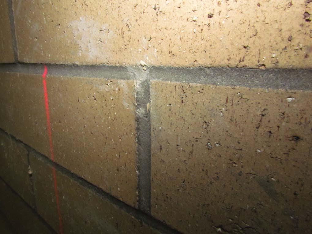
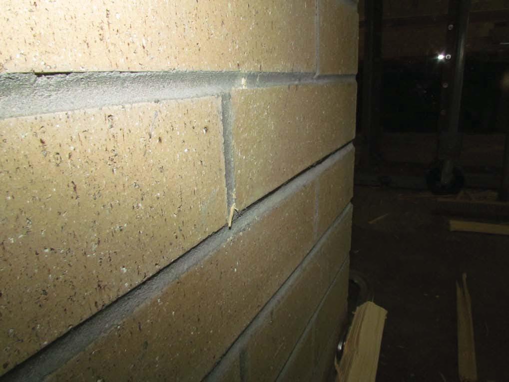
3 Spec. / Impact No. Velocity (mph) Location Impact Tests Results 1/ Panel center Unremarkable damage; see photos, page 5. 1 / Top right corner Unremarkable damage; see photos, pages 6 & 7. 1 / Bottom left corner Unremarkable damage; see photos, pages 8 & 9. 2 / Bottom left corner Unremarkable damage; see photos, pages 10 & / Panel center Unremarkable damage; see photos, pages 12 & / Top right corner Unremarkable damage; see photos, pages 14 & / Top right corner Unremarkable damage; see photos, pages 16 & / Panel center Unremarkable damage; see photos, pages 18 & / Bottom left corner Unremarkable damage; see photos, pages 20 & Page
4 5.0 CONCLUSIONS Within the bounds of reasonable engineering and technical certainty, and subject to change if additional information becomes available, the following is my professional opinion: Impact tests were conducted on April 26, 2012 on three series of brick panels for Western States Clay Products Association. The panel products included the following: Series 1 Panel: Nominal 8-in. x 4-in. x 16-in. (w x h x l) clay brick, unit compressive strength F'm = 3000 psi, with Type S mortar, grout full, #4 rebar at 24-in. on center. Series 2 Panel: Nominal 6-in. x 4-in. x 16-in. (w x h x l) clay brick, unit compressive strength F'm = 3000 psi, with Type S mortar, grout full, #4 rebar at 24-in. on center. Series 3 Panel: Nominal 8-in. x 4-in. x 16-in. (w x h x l) clay brick, unit compressive strength F'm = 3000 psi, with Type S mortar, grout full, #4 rebar at 48-in. on center. Tests on all three series were successful and qualifies each panel assembly to meet the debris impact guidelines of FEMA 320/361 and ICC-500. Debris impact resistance is based on the scheduled reinforcement. A structural engineer should check the design for bending resistance to a 250 mph wind force for the specific designed wall height of the proposed shelter or building. All tests were conducted in strict accordance to the guidelines of FEMA 320/361, ICC-500. Refer to Appendix A for test protocols. The WISE at Texas Tech University looks forward to the opportunity to working further with your company. Engineer of Record Larry J. Tanner, P.E. 4 Page

5 Series 1 Impact 1 5 Page

6 Series 1 Impact 2 6 Page
7 7 Page

8 Series 1 Impact 3 8 Page
9 9 Page

10 Series 2 Impact 1 10 Page
11 11 Page

12 Series 2 Impact 2 12 Page
13 13 Page

14 Series 2 Impact 3 14 Page
15 15 Page

16 Series 3 Impact 1 16 Page
17 17 Page
18 Series 3 Impact 2 18 Page
19 19 Page
20 Series 3 Impact 3 20 Page
21 21 Page
22 APPENDIX A TEST PROTOCOLS The Wind Science and Engineering research Center performs debris impact tests on storms shelters, shelter components, and building materials to evaluate their ability to resist various types of projectiles propelled at different speeds in accordance to accepted and proposed test protocols as follows: Protocols for Debris Impact Testing Protocol 1 Protocol 2 Protocol 3 Protocol 4 Protocol 5 Hurricane envelope impact by a 9 lb. wood 2 x4 propelled at 34 mph, in accordance with the Florida building Code, the International Code Council and the Texas Dept. of Insurance windstorm Resistant Construction Guide. Hurricane shelter speed impact by a 9 lb. wood 2 x4 propelled at 0.40 x the design wind speed (mph) for horizontal impacts and 0.10 x the design wind speed (mph) for vertical impacts, in accordance to the proposed ICC ICC/NSSA Standard for the Design and Construction of Storm Shelters. Hurricane shelter speed impact by a 9 lb. wood 2 x4 propelled at 0.50 x the design wind speed (mph) for horizontal impacts and 0.33 x the design wind speed (mph) for vertical impacts, in accordance with FEMA 320, Taking Shelter from the Storm, 2008 Edition and FEMA 361, Design and Construction Guidance for Community Saferooms, 2008 Edition. Tornado shelter speed impact by a 15 lb. wood 2 x4 propelled at 100 mph for horizontal impacts and 67 mph for vertical impacts, in accordance with FEMA 320, Taking Shelter from the Storm, 2008 Edition and FEMA 361, Design and Construction Guidance for Community Saferooms, 2008 Edition. Department of Energy (DOE) Impact Standards 1 The ICC 500 ICC/NSSA Standard for the Design and Construction of Storm Shelters is a referenced standard in the 2009 editions of the International Residential Code and the International Business Code. This is a Life Safety Standard which uses an Extreme Wind Map for Hurricanes with wind speeds starting at 225 mph and with contours along the Atlantic and Gulf Coast stepping inland in 10 mph increments to 160 mph. 22 Page
23 Introduction The primary objective in debris impact testing of storm shelters and shelter components is to assure compliance with a high standard of performance in protecting shelter occupants from windborne debris. Performance criteria include preventing perforation of the shelter or component by the design missile and preventing deformations which could cause injuries to the occupants. Test Criteria The testing described is for simulated windborne debris. The primary simulations are impacts of a 2x4-in. wood board traveling along the board s longitudinal axis, striking the test subject perpendicular to the test subject face. Standards that use this type of simulated debris include ASTM E & ASTM E Standard Test Method for Performance of Exterior Windows, Curtain Walls, Doors, and Impact Protection Systems Impacted by Missiles and Exposed to Cyclic Pressure Differentials, SSTD SBCII Test Standard for Determining Impact Resistance From Windborne Debris, ANSI A , Testing and Rating of Severe Windstorm Resistant Components for Swing Door Assemblies, ICC 500 ICC/NSSA Standard for the Design and Construction of Storm Shelters, and Texas Tech University, Wind Science and Engineering s Tornado Test Criterion adopted by the Federal Emergency Management Agency in publication FEMA 320, Taking Shelter from the Storm, and FEMA 361, Design and Construction Guidance for Community Shelters. The hurricane test criterion uses a 9-lb. 2x4-in. wood board, called a missile, traveling horizontally at 34-mph (50 feet/second), which corresponds to a mph wind, and is the criterion used for property protection. The tornado test criterion uses a 15-lb. 2x4-in. wood board traveling horizontally at 100-mph, which corresponds to a 250-mph wind, and is the criterion used in designing vertical surfaces for occupant protection. The criterion for falling debris from a tornado is a 15-lb. 2x4-in. board traveling at 67-mph striking perpendicular to the surface. The 67-mph criterion is used for surfaces horizontal to the ground and inclined less than 30-degrees. Additional factors of safety are inherent in the criterion since there is a very small probability that a missile will be traveling along its axis and will strike perpendicular to the surface. 23 Page
24 Test Procedure The first test on a system is to determine if the basic concept or structural element is capable of resisting the impact. This done by impacting the target in a general field or the area deemed most vulnerable. If the system resists the impact then the testing is concentrated on connections and material support conditions. Shelter walls or test panels are impacted with three test missiles in different and vulnerable locations. Shelter roofs/ceilings constructed differently from the walls are impacted with three test missiles in different and vulnerable locations. Shelter appurtenances, vents, louvers, windows, electrical boxes, shelves, seats, etc., are impacted by a single missile. Laboratory pressure tests are not conducted on shelters and shelter panels. Numerical analysis of wind pressures is outlined in the above listed standards in the Test Criteria. Pressure tests are required for swinging door assemblies. In accordance to FEMA 320, the residential shelter guideline, swinging door assemblies should resist a static pressure of 1.37-psi for a 5-second period. In accordance to FEMA 361, the community shelter guideline, swinging door assemblies should resist a static pressure of 1.75-psi for a 5-second period. Pass/Fail Criteria The criterion for the shelter/shell/panel test pass/fail is as follows: 1) The test subject must be impacted by a minimum three missiles in areas of perceived vulnerability; 2) The missile may penetrate that test subject, but may not perforate the safe side (back face) of the subject; 3) The test subject permanent deflection after impact must be less than 3-in.; 4) Segments, spallings or otherwise de-laminated portions of the test subject, though still attached to the subject, may not extend into the safe compartment 3-in. or more; and 5) Segments of the test subject or appurtenances attached to the test subject must not be ejected or otherwise released into the safe compartment by the impact force. Passage of the shelter door tests requires: 1) The door assembly must hold the required test pressures, 2) Resist perforation by the missiles, 3) Exhibit permanent deflection less than 3-inches, 4) Prevent disassociation of door components or shelter wall materials into the safe compartment, 5) Maintain two door locking points engaged and locked. FEMA 320/361 recognizes that one test missile can destroy or otherwise disengage one locking point. The guideline therefore requires that at least two locking points remained engaged and doors with only two points of locking must have both locks remain engaged and locked at the conclusion of the impact tests. 6) Pass/fail rating of the door relates to the full door assembly, including door, locking hardware, hinge, hinge screws and door frame. 24 Page
25 Test Equipment Debris Impact Air Cannon: 1) Air Tank 30 gallon, Manchester Model Number ) Electric Over Air Valve Matryx Model Number MX ) 4-in. aluminum quick coupler to connect barrel to valve. 4) 4-in. x 20-ft. long schedule 40 PVC barrel. 5) Pair Optical Timing Sensors Keyence Model Number PZ251R and PZ125T 12/24- volt. 6) Signal Conditioner. 7) Pair Precision Timers BK Precision Timer Model Number 1823 Universal Counter. 8) Control panel with pressure controls, laser sighting and a three stage firing system to eliminate unintentional missile shots. 9) Horizontal articulating cannon carriage with DC motor drive and variable speed controller. 10) Cannon carriage mounted to a hydraulic scissor lift on wheels - Autoquip Model Number 84B16F20. 11) Steel reaction frame made of vertical and horizontal steel beams anchored to the floor to provide simple support at the top and bottom of the test specimen. 25 Page
26 Use of Testing Report, TTU and WISE Logos The written report and supplemental photos and/or videos may be referenced or distributed by your company. But, Texas Tech University cannot endorse products nor can the name of the University or any of its units or personnel be used in advertising without first securing written permission from the University. Any misuse or misrepresentation of the report and/or pictures will result in action being taken by the University against the responsible parties. Storm shelter manufacturers or producers who have had products tested at Texas Tech University can use the Texas Tech University Wind Engineering logo provided they conform to the following: I. The Texas Tech University Wind Engineering logo may not be so prominent as to mislead the public or unduly play upon the Texas Tech University Wind Engineering name. II. Whenever the logo is used one of the two alternative statements below is to be employed in the text: Alternate 1 whole shelter The use of the Texas Tech University Wind Engineering logo signifies that the complete shelter structure was tested and successfully passed missile impact resistance tests at Texas Tech University. Alternate 2 - shelter component The use of the Texas Tech University Wind Engineering logo does not signify that the entire shelter structure was tested at Texas Tech, but rather only [shelter component name explicitly] was tested and successfully passed missile impact resistance tests at Texas Tech University. III. All advertising and promotional texts containing the use of the Texas Tech University Wind Engineering logo are to be presented to the Texas Tech University Office of Technology Transfer and Intellectual Property for review and approval before distribution. Texas Tech University will challenge any use of the Texas Tech University Wind Engineering logo that does not conform to the above standards. 26 Page
27 APPENDIX B Manufacturer Product Specifications 27 Page