GEOREFERENCED DGPS MAPPING 765kV S/C TRANSMISSION LINE PROJECT
|
|
|
- Clifton Booker
- 5 years ago
- Views:
Transcription


1 GEOREFERENCED DGPS MAPPING 765kV S/C TRANSMISSION LINE PROJECT System Strengthening Scheme for IPPs in Chhattisgarh & Other Generation Projects in Western Region T & D Business Headquarters : G - 55, MIDC, Butibori, Nagpur Maharashtra, India. Phone : , Fax : conhct@transrailltd.com Webmail : www. transrailltd.com CIN : MH1922P1C000997
2 Table of Contents 1. Project Details Introduction Project Scope Location of the Project Methodology / Philosophy of Route Selection Route survey techniques: DGPS Survey Legal Frame Work Environmental Assessment Forest involvement / Clearance Project Cost Approvals and Clearances ANNEXURES I. DIST. JANJGIR CHAMPA - Digitized Village Maps showing DGPS Coordinates & Statement of forest land Doc No. FC_CD CWRTL-DOC-001, Rev.0 Page : 2
3 Doc No. FC_CD CWRTL-DOC-001, Rev.0 Page : 3
4 1. PROJECT DETAILS 1.1 Introduction In accordance with the Electricity Act, 2003, Regional Power Committees (RPC) have been constituted by the Central Government for the specified Region(s) for facilitating the Integrated operation of the power system in the Region and to facilitate interstate/inter-regional transfer of power and to facilitate all functions of planning relating to inter-state/ intrastate transmission system with CTU/STU. As per the 36th Standing Committee meeting, it was decided to strengthen the power evacuation system from Vindhyachal, Sasan Generating stations and Chhattisgarh region following scheme are required. As part of the above reinforcement requirement of the transmission network the following transmission elements got evolved as Chhattisgarh and other Generation projects in Western Region. 1. Vindhyachal-IV & V STPP Vindhyachal Pool 400 kv D/c (Quad) 2nd line nos. 400 kv Line bays at Vindhyachal V STPP switchyard kv S/c (2nd) line from Sasan UMPP to Vindhyachal Pool substation (PGCIL) no. of 765 kv line bay at Sasan UMPP of M/s SPL. Reliance. 5. LILO of one circuit of Aurangabad (PGCIL) Padghe (PGCIL) 765 kv D/c line at Pune. 6. Raigarh (Kotra) - Champa (Pool) 765 kv 2ndS/c line. 7. Champa (Pool) Dharamjaigarh 765 kv 2ndS/c line. 8. Gwalior 765/400 kv Morena 400 kv D/C line 9. Establishment of 2X315 MVA, 400/ 220 kv substation Further, the empowered committee in its 32nd meeting decided that the above system shall be put into competitive bidding. The Government of India, Ministry of Power, vide Gazette Notification dated July 08, 2014 has notified PFC Consulting Limited to be the Bid Process Coordinator (BPC) for the purpose of selection of Bidder as Transmission Service Provider (TSP) to Doc No. FC_CD CWRTL-DOC-001, Rev.0 Page : 4
5 establish Transmission System for Chhattisgarh and other Generation projects in Western Region through tariff based competitive bidding process. M/s ATL became successful bidder and acquired the Special Purpose Vehicle (SPV) Raipur-Rajnandgaon-Worora Transmission Ltd. 1.2 Project Scope The scope of this project will include: Transmission System for System Strengthening for IPPs in Chhattisgarh and Sl.No. other Generation Projects in Western Region Name of the Transmission Element kv Interconnection at Gwalior 765/ 400 kv S/S i) ii) Gwalior 765/400 kv Morena 400 kv D/C Establishment of 2 X 315 MVA, 400/ 220 kv substation at Morena 400 kv - Line bays 2 nos. - ICT 2 x 315 MVA, 400/ 220 kv - ICT bays 2 nos. - Bus reactor: 1X125 MVAR - Space for 400 kv bays 4 nos. 2. i). ii) 3. i) ii) iii) iv) v) 220 kv - Line bays 4 nos. - ICT bays 2 nos. Space for 220 kv bays 4 nos Additional evacuation line from Vindhyachal-IV & V STPP (3x500 MW) Vindhyachal-IV & V STPP Vindhyachal Pool 400 kv D/C (Quad) 2nd line 2 Nos. 400 kv Line bays at Vindhyachal - V STPP switchyard Additional System Strengthening Scheme for Chhattisgarh IPPs (Part-A) Sasan UMPP Vindhyachal Pooling station 765 kv S/C line 1 no. of 765 kv line bay at Sasan UMPP of M/s SPL, Reliance LILO of one circuit of Aurangabad Padghe 765 kv D/C line at Pune Raigarh (Kotra) - Champa (Pool) 765 kv 2nd S/C line Champa (pool) Dharamjaigarh 765 kv 2nd S/C line Doc No. FC_CD CWRTL-DOC-001, Rev.0 Page : 5
6 1.3 Location of the Project Major element of this projects is in Madhya Pradesh state(60 % of total Project scope) and rest of elements are in Chhattisgarh State (35% of total project scope) and Maharashtra State (5% of total project scope). S.No. Description Tentative Line Length (Km) State involved kv D/C Gwalior - Morena Line 49 Madhya Pradesh /220 kv, 2X315 MVA Morena substation - Madhya Pradesh 3 400kV D/C Vindhyachal-IV & V STPP- Vindhyachal pool Line 28 Madhya Pradesh 4 2 Nos 400 kv Line bays at Vindhyachal - Madhya Pradesh kv S/C Sasan UMPP-Vindhyachal pooling station 6 Madhya Pradesh 6 765kV Line bay at Sasan UMPP of M/s SPL, Reliance - Madhya Pradesh 7 LILO of One circuit of Aurangabad- Padghe 765 kv D/C Line at Pune 64 Maharashtra kv S/C line Raigarh Champa (Pool) 94 Chhattisgarh kv S/C line Champa (Pool)- Dharamjaigarh 49 Chhattisgarh Doc No. FC_CD CWRTL-DOC-001, Rev.0 Page : 6

7 1.4 Methodology / Philosophy of Route Selection In order to execute such magnitude of transmission system, selection of the line route is a very important criteria, however while deciding the route all the guidelines, rules, acts, etc. of the state as well as central has been taken in to account. As transmission lines have to traverse from generating stations to load centers and beneficiary states, the topographical & geographical nature of the terrains play significant influence in the implementation of project as well as the project cost. Hence, it is essential that at the planning stage itself various alternative routes and technical solutions for transmission lines be examined in detail. Presently, conventional methods of survey like walk over survey, preliminary survey and detailed survey are carried out at various stages from conceptualization of the project to implementation. There are new means available which are used to conduct route survey using Google, DGPS based survey etc. Doc No. FC_CD CWRTL-DOC-001, Rev.0 Page : 7
8 Following are the major factors taken into account while deciding the line route of the project as per the provisions of the acts and rules a. Major habitation & settlement area avoided. b. Wild Life Sanctuary s, Biosphere s, Dense forest avoided. c. Minimum vegetation / tree cutting in the line route d. Minimum no of River Crossings, Railway Crossings, Highway Crossings, Power Line Crossings are considered. e. Lowest minimum forest area demand in the proposed route f. Archeological structures, defense sites, airport area, etc are avoided. g. Accessibility of approach road to the project site. h. Rich gardens, plantations, notified industrial area, etc to be avoided. i. Economic viability of the route 1.5 Route survey techniques: Preliminary & Route Alignment Survey Preliminary Survey included the following steps: Map study Walkover survey Map Study After drawing various routes of alignment network within the Topo maps, a comparative study was made on the basis of the following data: Route length. Nos. and type of important road points in each indicating alignment of each road as measured on the map. Nature and number of major crossings. Mapping the industrial installations, structures, and important places for identification of Roads. Approach to the line in general for construction & maintenance. Reaches through protected or Reserved Forests Continuously long stretches in paddy fields. Close parallelism with Railway lines. Doc No. FC_CD CWRTL-DOC-001, Rev.0 Page : 8
9 Walkover Survey was carried out going over the area associated with the routes and collecting features observed other than those existing on the map. In addition the indications on following features are also checked: Communication lines Accessibility and smoother approach. Logistics of the route. Existing and Present course of River Power lines (existing) Expanding villages and towns Rich gardens and plantations Reserved forests and high tree areas, National Parks & Wild life sanctuaries Archeological monuments, Aerodromes, radar centers etc. Steep sloping terrain, Areas prone to land slides, soil instability etc. Prohibited areas declared under statutory regulations Remote Sensing: Remote Sensing is modern technique in mapping sciences. It is now a major tool to map any area on earth s surface for transmission of power. The planning for installation of large transmission towers needs proper planning. For this, updated base maps are required. Remote sensing imageries can help in updating the available topographic maps. The recently launched satellites like IKONOS, IRS-1C, 1D (PAN) having its very good spatial resolution of 1mt and 5.8mts through digital image processing techniques; it is able to identify even small features with the resolution as given above. To select site for putting new transmission towers and lines especially in hilly terrains, the density of trees, elevation differences has to be carefully studied in detail. In such cases, remote sensing is the main technology, plays a vital role for the preparation of database on landforms, land use / land cover and related database. Integrating these information in GIS platform, it is able to generate three dimensional terrain model (DTMs) of the area, which can be further updated with the multi dated satellite images and aerial photographs also Digital Photogrammetry is the potential technology to provide the information s on terrain elevation which has to be studied before locating site for transmission towers and lines. This has found great success Doc No. FC_CD CWRTL-DOC-001, Rev.0 Page : 9
10 in many European countries but yet to be implemented in the developing countries like India. Satellite Image (Google Map): Satellite Images were used as most authoritative document to record latest topographical changes along the surveyed routes. This involved the initiations of the following activities. Transferring of images to studios for processing and detailed measurements. Ground Verification was undertaken to study the authenticity of the images. Camera is supposed to see topographic details vividly, that is the only reason, why satellite images are used in detailed survey in comparison to the traditional field work. The ground profile in digital form could be obtained from satellite images, which in turn enable the user to estimate various types earthwork involved like benching, revetments etc. could be computed by using the relevant software. Appropriate techniques for obtaining soil conditions, depth of ground water, terrain conditions etc. for correct estimation of civil works could be explored. Due to Shadow Effect, some errors crop up in the satellite imageries, which affect the preliminary surveys, and it becomes difficult to differentiate between the forests and other greenery, consequently it becomes difficult to mark the forest boundaries etc. Proper resolution plays an important role in interpreting satellite images; higher resolution improves the quality of visual Context and may differentiate the ground realities closely. Relief data and subsoil data cannot be assessed from Satellite imageries. Digitization of Complete Zonal maps, rather selected features would provide a complete replica in integrated environment. Satellite data of resolution 1 5.8m will be preferable. How ever, the overall cost economy shall have to be worked out, as this data will be more costly, but will avoid field assignment in many places. Symbols of physical features in satellite imageries are not easily recognized by transmission line engineers. Doc No. FC_CD CWRTL-DOC-001, Rev.0 Page : 10
11 Three (3) alternate route alignments were carried out by help of satellite images available in google map. Physical walk over survey was conducted on all the three routes and DGPS / GPS coordinates were collected at every 100 meters along with soil strata. Based on the information so collected, the best route was selected after evaluation of factors like, minimum forest coverage, angle points, river crossing, power line crossing, habitation etc. The Infrastructural details along the routes between Champa (pool) Dharamjaigarh 765 kv 2nd S/C line are as follows: Name of Proposed Transmission line between : 765 kv S/C line between Champa and Dharamjaigarh District : Janjgir champa and Korba Total No. Angle Points : 38 Total Route Length : kms Terminal points : Major Crossings along the route : Total H.T. Line : Champa substation: Latitude '3.747" Longitude '23.497" Dharamjaigarh substation: Latitude '4.109" Longitude '33.622" Total - 17 nos. 132 kv -3 nos, 220 kv -3 nos, 400 kv -5 nos., 765 kv -5 nos, 800 kv HVDC-1 no. Total Railway Line : 2 nos. National Highway (NH) : 1 no. (NH-200) State Highway (SH) : Nil River Crossing : Major River : 1 no. Mand River -523 mtr : Minor River: Nil Doc No. FC_CD CWRTL-DOC-001, Rev.0 Page : 11
12 Name of Proposed Transmission line between : 765 kv S/C line between Champa and Dharamjaigarh Forest /Sanctuary : ~24 Ha Forest Land involvement. No sanctuary / ESZ. Towns, Cities & villages along the route : The route alignment is avoiding towns/inhabitants. Minerals in the route corridor : Nil a) Crops Paddy, Rahar, Lentil, Soyabin, Gram, and etc. Type of Crops Forest Land, Hill are along the route : b)soil c) land Plan (90%) d) Hill 10% Clayeyey silt of low of plastisity for details of the soil investigation please refer Annexure-8. Land Involvement : Climate : Specific feature : Combination of barren and agriculture Summer= March to June, Monsoon= July to October, a) Seasons Winter= November to February b) Maximum 49 C Temperature c) Minimum 8 C Temperature This alternative route-1 having comparatively less route length( kms), well connected by road network which makes it convenient for construction and maintenance of T/L. Hence, this alternative route is feasible & economical and being considered for execution. 1.6 DGPS Survey DGPS is a satellite based system developed and maintained by US Department of Defence. In this system 28 satellites are orbiting round the globe in six different planes which gives the coordinates of any point on the globe. The technology gives high accuracy coordinates when observed in differential GPS mode. In the survey, differential GPS technology was used for maintaining the overall control and accuracy of the survey exercise. DGPS control stations were established in the proposed area for one hundred and twenty minute of observation time for each angle point. The observed data was post processed to get the final DGPS survey results in UTM map projection system with 44 North zone parameters and WGS84 datum. Doc No. FC_CD CWRTL-DOC-001, Rev.0 Page : 12
13 Following methodology was adopted for the work. The accuracy of the DGPS instruments used was 5mm +/-1ppm in static mode, which is sufficient for the said project. Preliminary study and Data preparation work : Locations of the DGPS Pillars fixed by the client were first studied. Location for camping of the team and their mobilization schedule was planned and the major town and accessibility from the town to the remotest rover location was assessed. Study of the existing available village maps, mine lease map and SOI toposheet. Simultaneously the team was mobilized to site, so that they will have the feel of the project, feel of the site conditions, and they were also made aware of the purpose / importance of the project. Planning of the Activities : Planning of the work is the most important activity in DGPS survey. In this exercise satellite data of the location to be surveyed was collected for fifteen minutes of observation, to collect the ephemeris data. The Planning activity defines the working schedule of the GPS observation. The ephemeris data was processed to know the availability of the satellite data for the working days. The time with good availability of satellites with minimum PDOP are selected for the work. The stages include First the ephemeris data was downloaded of the area of interest. All the activities were planned based on the best availabilities of the satellite vehicle and minimum PDOP value. Identification of the Base and Reference: After the reconnaissance survey and planning, next task was to identify and establish the main reference point for the survey work. For the Elevations, reference considered was from a Bench Mark inside the mine area as given by client. For horizontal reference the DGPS Survey in UTM/WGS 84 for the base data was used. The EPOCH was set at 15 sec and the data was collected in UTM/WGS84 projection system with Doc No. FC_CD CWRTL-DOC-001, Rev.0 Page : 13
14 44N zone parameters. The elevation mask for the observation was kept as 13 with reference to the Horizon. Following is the list of the Base stations established in the area of interest. The DGPS observations were carried out on all the angle point / entry & exit point of the proposed route through forest. The rover locations were established by the client. In all GCPs were fixed on site. The data for each GCP was recorded in the DGPS Detail Form and digital photographs were taken for future reference. The data from the DGPS was down loaded on day today basis through Trimble Data Transfer software. This data was then processed in Trimble Geomatic Office software to resolve the ambiguity using the UTM Standard 44 North zone parameters. The Base lines were processed to get the required accuracy. 1.7 Legal Frame Work It is proposed to execute the above entire transmission system as per provisions contained in the Indian Electricity Act 2003 and the rules made there under and the Electricity (Supply) Act 1910 and Doc No. FC_CD CWRTL-DOC-001, Rev.0 Page : 14
15 2. ENVIRONMENTAL ASSESSMENT 2.1 Forest involvement / Clearance As per the practice, preliminary route selection is done based on such documents as the Forest Atlas and the survey of India maps using bee line method followed by field clarification through walk over survey. All possible steps are taken to avoid the route alignment through forest. In case where it becomes unavoidable due to the geography of terrain, the alignment is made in such a way that the route through the forest is the barest minimum For selection of optimum routes following points are taken into consideration: i. The route of the transmission line does not involve any human rehabilitation. ii. Any monument of culture or historical importance is not getting affected. iii. The route does not create any threat to the survival of any community with special reference to tribal. iv. It does not affect any Public Utility Services like Play Ground, School, etc. v. It does not pass through any Wildlife Sanctuaries, Nation Park, etc. vi. It does not infringe with areas of natural resources. vii. 15 kms. away from major towns to account for future urban expansion In case where it becomes unavoidable due to the geography of terrain, the alignment is made in such a way that the bare minimum line route through forest is selected. Name of Transmission line Forest Involvement (Approx. Length in km) 765 kv S/C line between Champa - Dharamjaigarh ~3.82 Doc No. FC_CD CWRTL-DOC-001, Rev.0 Page : 15
16 3. PROJECT COST The total project cost including taxes and duties works out to INR 105 crores for Transmission line project from Raipur to Rajnandgaon to Wardha (Maharashtrra). 4. APPROVALS AND CLEARANCES Following approvals and clearances need to be obtained from the various authorities at the different stages of the project. Close follow up will be exercised for the timely approval of the below items. Sr No Statutory Clearances Concerned Authority 1 Approval Under section 68 of E.A 2003 MoP 2 Transmission License CERC 3 Tariff Adoption CERC 4 Forest Approval MoEF 5 Aviation AAI 6 PTCC clearance CEA 7 Power Line Crossing Concern Utility 8 Railway Crossing Railway Authority 9 National Highway Crossing NHAI 11 Final Charging Clearance approval CEA Doc No. FC_CD CWRTL-DOC-001, Rev.0 Page : 16
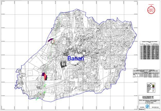
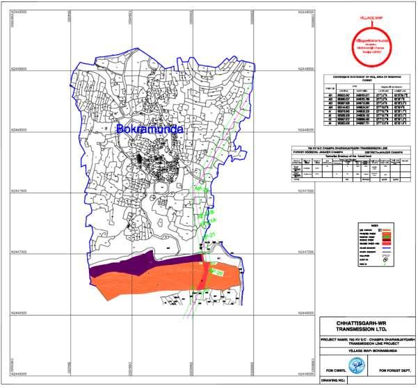
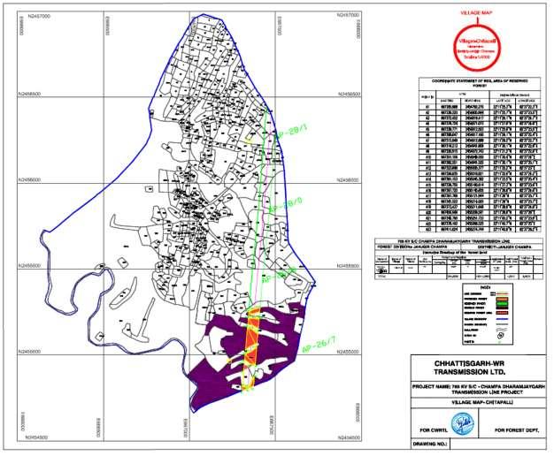
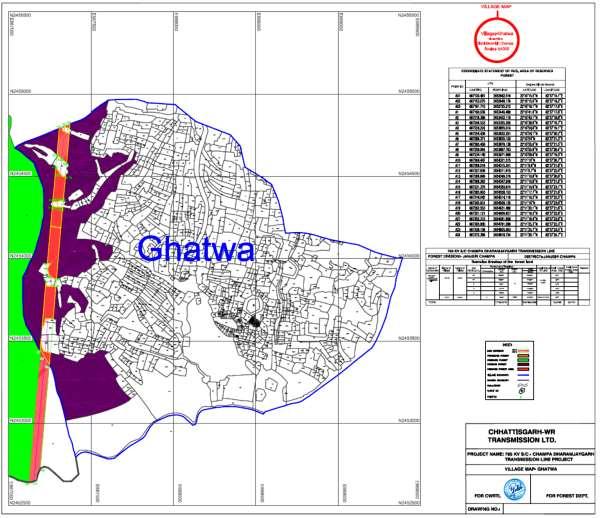
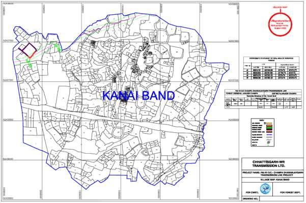
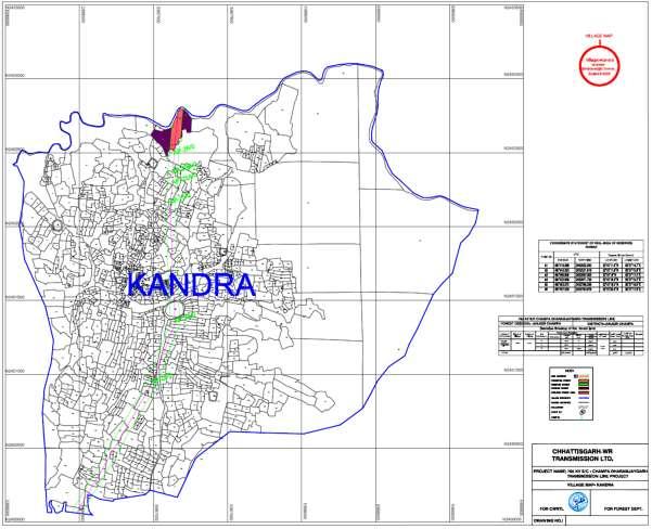
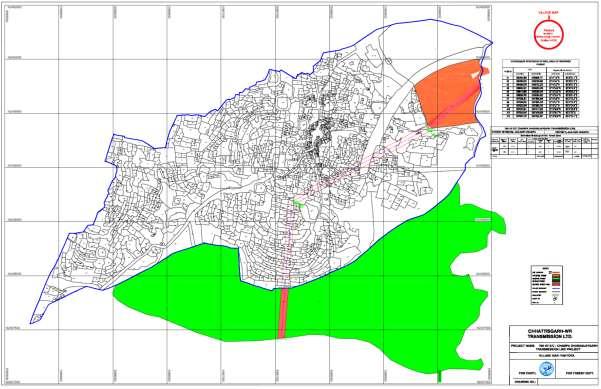
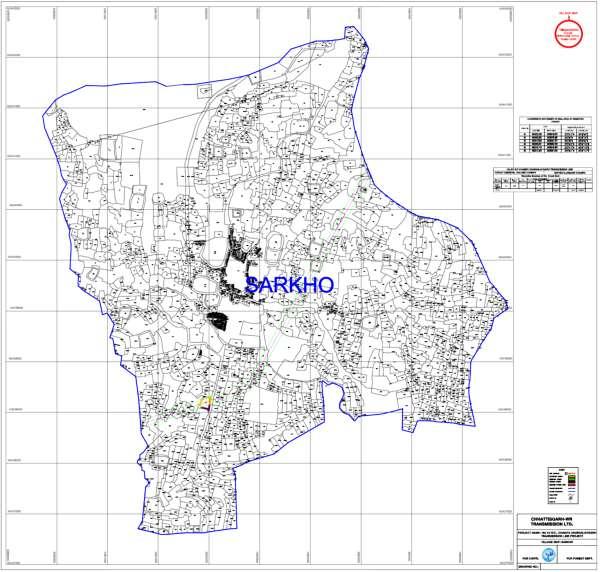
17 ANNEXURE I DIST. JANJGIR CHAMPA GEOREFERENCE MAPS Doc No. FC_CD CWRTL-DOC-001, Rev.0 Page : 17
18 Doc No. FC_CD CWRTL-DOC-001, Rev.0 Page : 18
19 Doc No. FC_CD CWRTL-DOC-001, Rev.0 Page : 19
20 Doc No. FC_CD CWRTL-DOC-001, Rev.0 Page : 20
21 Doc No. FC_CD CWRTL-DOC-001, Rev.0 Page : 21
22 Doc No. FC_CD CWRTL-DOC-001, Rev.0 Page : 22
23 Doc No. FC_CD CWRTL-DOC-001, Rev.0 Page : 23
24 Doc No. FC_CD CWRTL-DOC-001, Rev.0 Page : 24
25 Doc No. FC_CD CWRTL-DOC-001, Rev.0 Page : 25