Exergy analysis of cooling systems and strategies
|
|
|
- Adam Reynolds
- 5 years ago
- Views:
Transcription
1 Exergy analysis of cooling systems and strategies Marco Molinari, KTH The Royal Institute of Technology, Sweden Petra Karlstöm, Basler & Hofmann AG Consulting Engineers, Switzerland
2 Relevance The demand for ventilation and cooling of buildings is an increasing share of Europe s total energy use in buildings The performance of HVAC systems is usually evaluated based on the first law of thermodynamics. Exergy-optimized systems make use of low temperature differences, which makes it possible to put to use renewable sources. Aim of this paper is to show the potential for optimization of three hybrid cooling systems This potential is addressed performing an exergy analysis of the cooling demand of a generic office building and of three supply systems, which use chillers in conjunction with evaporative cooling
3 Building model Office building Floor area : 1200 m 2 Walls area: 500 m 2, U-value of 0.15 W/(m 2 K) Windows area : 250 m 2, U-value 1 W/(m 2 K) Internal loads: 10 W/m 2 External loads: 15 W/m 2 Set-point temperature, indoor environment : 26 C Outdoor temperature: 30 C Reference conditions Environment temperature: 30 C Environment pressure : 110 kpa. Humidity ratio: 0.01 kg w /kg a, RH= 40%. Calculation of the cooling load, steady-state Q cooling = U windows A windows (T in -T out )+U walls A walls (T in -T out )+Q int +Q ext The obtained cooling load has been in all the three cases 31,500 W, delivered cooling power : 26 W/m 2
4 Cooling systems description Hybrid cooling tower Hybrid cooling tower From environment Fan Ad. saturator Heat exchanger air / water To environment From environment Fan Ad. saturator Heat exchanger air / water To environment Pump Chiller From environment Hybrid cooling tower Ad. Fan saturator Heat exchanger air / water To environment Pump Chiller Pump Heat exchanger air / water Pump Chiller Fan Heat exchanger air / air Pump Duct Heat exchanger water / air Fan Duct Pump Floor cooling Pump Floor cooling Air cooling Air Water Room Environment Air Water Room Environment Air Water Room Environment System 1 System 2 System 3

5 Software tool: SEPE
6 Components

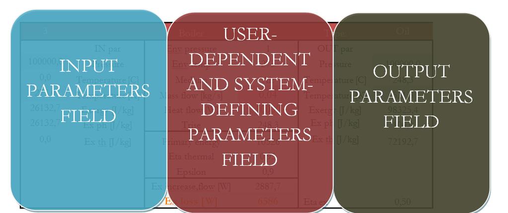
7 Nodes description
8 Exergy calculations Ex,spec=f(T,T0,P,P0,ω, ω0) Ex spec Ex th Ex pr Ex ch Exergy flow Exergy flow Exergy flow m i ex spec Exergy flo i 1 w i Ex Ex th Ex pr c p ( T P T0 Rln P 0 T0 ) T ln ch R T i ln i ln i T T 0 i 0
9 Exergy supply and demand of the analyzed systems
10 Exergy losses in the cooling systems
11 Conclusions All three systems have a low exergy efficiency. The exergy demand for the building is low. The main losses occur in the generation systems, chillers and hybrid cooling tower, and in the heat exchangers. The system with the highest exergy efficiency in the analysis is the System 2. Water: lower temperature difference No heat exchanger Direct distribution of the chiller output to the emission system doubles the exergy efficiency in comparison with a system where an intermediate heat exchanger is necessary. Exergy potential in the outdoor air at mid European humidity conditions: for System 2, the exergy gained from the outdoor air is in the level of the losses from the chiller.
12 References Karlström, Petra, and Gudni Jóhannesson. "A general procedure to model the exergy performance of hybrid HVAC systems in buildings." Bausim Molinari, Marco. SEPE: an excel calculation tool for exergy-based optimizations. ECBCS Annex 49 Newsletter 6, Molinari, M A pressure and thermal exergy analysis of a waterborne and an airborne system, Proceedings of the 15th Building Services, Mechanical and Building Industry Days International Conference, Debrecen.

13 Aknowledgements The present work is the result of a collaboration within the IEA ECBCS Annex 49. The work carried out by Basler & Hofmann AG was funded by the Swiss Federal Office of Energy.
14 Thank you for your attention!