WRF-Hydro Modeling System: Physics Components
|
|
|
- Arabella Baker
- 5 years ago
- Views:
Transcription

1 WRF-Hydro Modeling System: Physics Components D. Gochis, W. Yu, D. Yates, K. Sampson, A. Dugger, J. McCreight, M. Barlage, A. RafieeiNasab, L. Karsten, L. Read, L. Pan, Y. Zhang, M. McAllister, J. Mills, K. FitzGerald National Center for Atmospheric Research
2 Outline: Basic Concepts Conceptualization of WRF-Hydro Model Architecture & Requirements

3 Basic Concepts: Linking the column structure of land surface models with the distributed structure of hydrological models in a flexible, HPC architecture.
4 Conceptualization of WRF-Hydro Atmospheric coupling perspective and serving the WRF research and forecasting and CESM communities Oriented towards existing NCAR-supported community models, but expanding: Not fully genericized coupling which has pros/cons associated Also aimed at cluster & HPC architectures
5 Goal
6 Current Land Surface Models: Column physics & land-atmosphere exchange Noah LSM & Noah-MP
 4. Soil moisture factor for stomatal resistance (3 options) 5. Runoff and groundwater (4 options) 6. Surface layer exchange coefficients (4 options) 7.")
7 NoahMP Column Physics: Noah-MP contains several options for land surface processes: 1. Dynamic vegetation/vegetation coverage (4 options) 2. Canopy stomatal resistance (2 options) 3. Canopy radiation geometry (3 options) 4. Soil moisture factor for stomatal resistance (3 options) 5. Runoff and groundwater (4 options) 6. Surface layer exchange coefficients (4 options) 7. Supercooled soil liquid water/ice fraction (2 options) 8. Frozen soil permeability options (2 options) 9. Snow surface albedo (2 options) 10. Rain/snow partitioning (3 options) 11. Lower soil boundary condition (2 options) 12. Snow/soil diffusion solution (2 options) Total of ~50,000 permutations can be used as multiphysics ensemble members Noah/NoahMP development lead by M. Barlage and F. Chen, NCAR
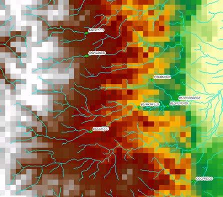

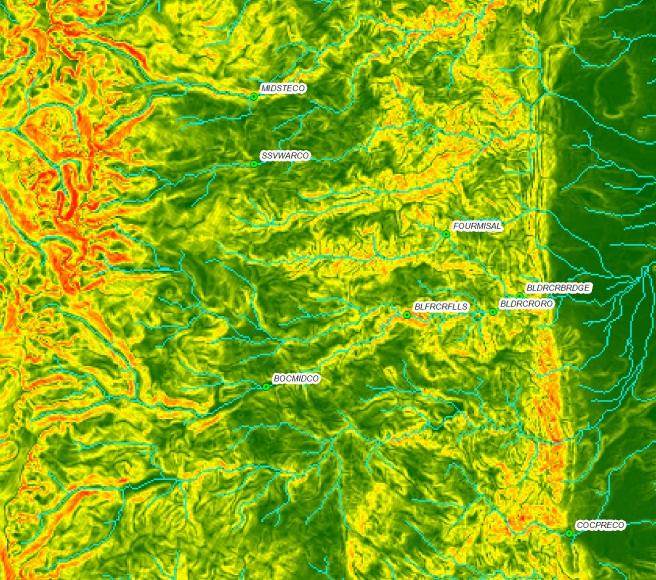
8 Multi-scale aggregation/disaggregation: 100m Terrain 1 km Terrain Current Regridding Implementing ESMF Regridders Terrain slope (0-45 deg)

9 Multi-scale aggregation/disaggregation:
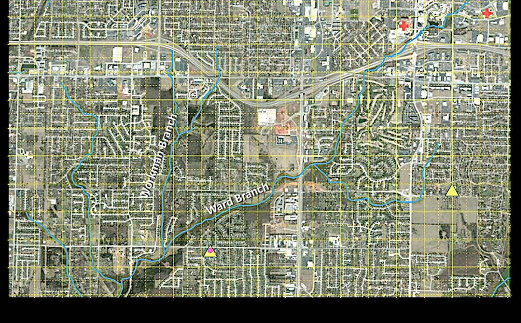
10 Surface routing: Infiltration excess available for hydraulic routing Pixel-to-pixel routing Steepest descent or 2d Diffusive wave/backwater permitting Explicit solution Ponded water (surface head) is fullyinteractive with land model Adapted from: Julian et al, 1995 CASC2D, GSSHA Sub-grid variability of ponded water on routing grid is preserved between land model calls
11 Subsurface routing: Surface Exfiltration from Saturated Soil Columns Quasi steady-state, Boussinesq saturated flow model Exfiltration from fully-saturated soil columns Anisotropy in vertical and horizontal Ksat No perched flow Soil depth is uniform Lateral Flow from Saturated Soil Layers Critical initialization value: water table depth Adapted from: Wigmosta et. al, 1994


12 Subsurface routing: 2d groundwater model Coupled to bottom of LSM soil column through Darcy-flux parameterization Independent hydraulic characteristics vs. soil column Full coupling to gridded channel model through assumed channel depth and channel head Detailed representation of wetlands Surface ponded water from coupled groundwater in WRF-Hydro B. Fersch, KIT, Germany


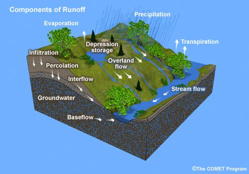
13 Runoff and Routing Physics: Overland Flow Lateral Subsurface Flow Simplified Baseflow Parameterization Channel Hydraulics Simple Water Management
14 Channel routing: Gridded vs. Reach-based Bw Solution Methods: Gridded: 1-d diffusive wave: fully-unsteady, explicit, finite-difference Reach: Muskingum, Muskingum-Cunge (much faster) Parameters: A priori function of Strahler order Trapezoidal channel (bottom width, side slope)

15

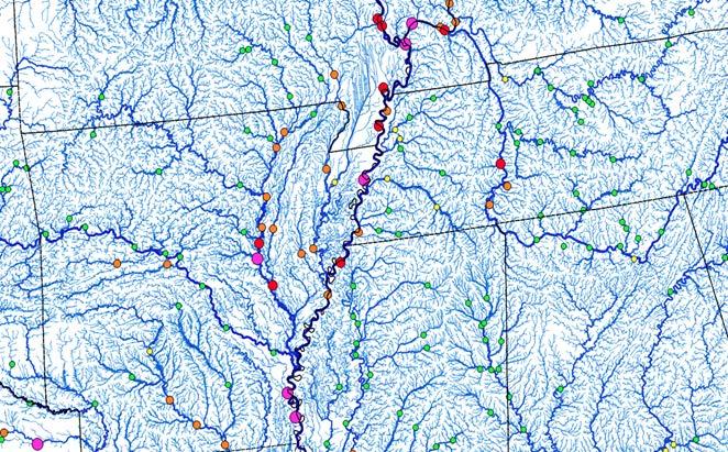
16 NHDPlust Reach Channel Network


17 Optional conceptual Bucket models: Used for continuous (vs. event) prediction Simple pass-through or 2-parameter exponential model Bucket discharge gets distributed to channel network
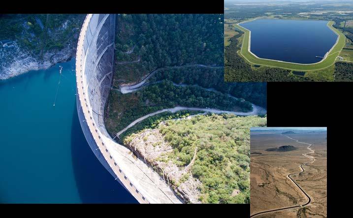
18 Optional lake/reservoir model: Level-pool routing (i.e. no lagging of wave or gradient in pool elevation) Inflows via channel and overland flow Discharge via orifice and spillway to channel network Parameters: lake and orifice elevations, max. pool elevation, spillway and orifice characteristics; specified via parameter table Active management can be added via an operations table Presently no seepage or evaporative loss functions
 Inflow")


19 : Lake/Reservoir Represenation Defined in GIS Pre-processing, integrated with channel hydrograph Specified spillway characteristics (length, height) Inflow Reaches Null Reaches Discharge Point single outlet Level Pool Scheme: 3 passive discharge mechanisms: Orifice flow Spillway flow Direct Pass-through Development: Basic thermodynamics (CLM/WRF lake model) Full lake accounting Evaporation Ice formation Inflows/outflows Simple management Coupling to FVCOM (GLERL)

20 Implementing lakes and reservoirs in WRF-Hydro Visualization of lake impacts Barker Reservoir Gross Reservoir

21 WRF-Hydro Model Architecture Model physics components. Multi-scale components. Rectilinear regridding ESMF regridding Downscaling
 Modes of operation..1-way vs.")

22 WRF-Hydro Model Architecture One-way ( uncoupled ) Two-way ( coupled ) Modes of operation..1-way vs. 2-way Model forcing and feedback components: Forcings: T, Press, Precip., wind, radiation, humidity, BGC-scalars Feedbacks: Sensible, latent, momentum, radiation, BGC-scalars
23 WRF-Hydro: