June i TABLE OF CONTENTS
|
|
|
- Garry Matthews
- 5 years ago
- Views:
Transcription

1
2 June i TABLE OF CONTENTS SECTION PAGE 1.0 INTRODUCTION Purpose of the Investigation Description of the Project and Scope of Work Site Geology Site Description and Surrounding Land Use SUBSURFACE INVESTIGATION SUBSURFACE CONDITIONS General Topsoil Silty Clay and Clayey Silt Groundwater Levels PROPOSED GAS MAIN CROSSING OF HIGHWAY General Excavation for Jacking and Receiving Pits General Excavation Basal Stability Working Pad on the Bottom of the Excavations Groundwater Inflow Backfilling of the Excavations for the Jacking and Receiving Pits Proposed Tunnel Bore Effects of the Proposed Highway 401 Tunnel Crossing... 8 In order following page 9 List of Abbreviations and Terminology Record of Borehole sheets Figures 1 and 2
3 June INTRODUCTION 1.1 Purpose of the Investigation This report presents the results of a subsurface investigation carried out at the site of a proposed gas main crossing of Highway 401 between Sir John A. MacDonald Boulevard and Sydenham Road in Kingston, Ontario. The purpose of the investigation was to advance a limited number of boreholes at the site and, based on the factual information obtained, we were to: provide preliminary geotechnical guidelines on specific aspects of the design of the project, including construction considerations that could influence design decisions; and comment on the effects of the proposed tunnel crossing of Highway 401 on the soil, groundwater and local conditions. 1.2 Description of the Project and Scope of Work Plans are being prepared to construct a utility crossing of Highway 401 for a proposed 250 millimetre diameter high pressure gas main. The crossing of Highway 401 will be located about 0.9 kilometres west of Sir John A. MacDonald Boulevard and about 70 metres west of the Little Cataraqui Creek (see Key Plan, Figure 1). The proposed highway crossing will likely be carried out using horizontal jack and bore tunnelling techniques in conjunction with a permanent steel casing, although directional drilling techniques may also be considered. If horizontal boring techniques are used, open cut receiving and jacking pits will likely be required on both the north and south sides of Highway 401 outside of the roadway allowance. 1.3 Site Geology Surficial geology maps of the Kingston area indicate that the site is underlain by deposits of silt and clay of glaciolacustrine origin. The overburden is indicated to be underlain by siltstone, dolomitic limestone and limestone of the Gull River formation. Surficial deposits of alluvium and/or organic material should also be expected along the creek. The Little Cataraqui Creek is down slope from the proposed tunnel crossing site.
4 June Site Description and Surrounding Land Use The topography in the area of the site of the highway crossing is undulating and slopes downward from west to east. Limestone bedrock outcrops are evident along the Highway 401 alignment to the west of the proposed crossing. The existing highway is in fill section. The site of the proposed crossing is grass and sparse tree covered. Currently, the north side of the highway is used for recreational purposes, and the site side is undeveloped.
5 June SUBSURFACE INVESTIGATION The field work for this investigation was carried out on November 29, 2004, at which time three (3) boreholes, numbered 1, 1A and 2, were advanced at the site to depth ranging from 5.2 to 5.9 metres below ground surface using a truck mounted, hollow stem auger drill rig owned and operated by Marathon Drilling Ltd. of Ottawa, Ontario. Standard penetration tests were carried out in the boreholes at regular intervals of depth and samples of the soils encountered were recovered using drive open sampling equipment. Well screens were installed in the boreholes to measure the groundwater levels in the overburden deposits. The field work was supervised throughout by a member of our engineering staff. Following completion of the field work, the recovered soil samples were returned to our laboratory. Selected samples of the soil were tested for water content. The results of the boreholes are provided on the Record of Borehole sheets following the text of this report. The approximate locations of the boreholes are shown on the Site Plan, Figure 2. The results of the water content determinations are provided on the Record of Borehole sheets. The borehole locations were determined in the field by personnel relative to existing site features. The borehole elevations were not measured.
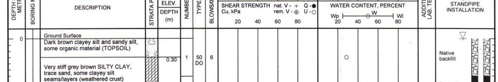
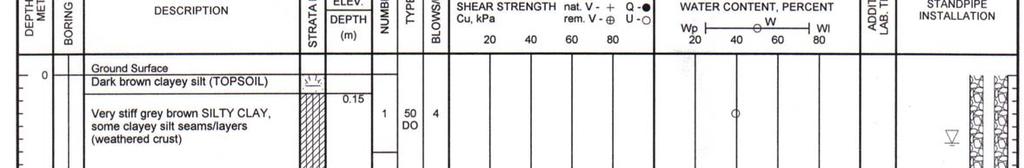
6 June SUBSURFACE CONDITIONS 3.1 General As previously indicated, the soil and groundwater conditions logged in the boreholes are given on the Record of Borehole sheets following the text of this report. The borehole logs indicate the subsurface conditions at the specific test locations only. Boundaries between zones on the logs are often not distinct, but rather are transitional and have been interpreted. Subsurface conditions at other than the borehole locations may vary from the conditions encountered in the boreholes. In addition to soil variability, fill of variable physical and chemical composition can be present over portions of the site. The soil descriptions in this report are based on commonly accepted methods of classification and identification employed in geotechnical practice. Classification and identification of soil and bedrock involves judgement and does not guarantee descriptions as exact, but infers accuracy to the extent that is common in current geotechnical practice. The following presents an overview of the subsurface conditions encountered in the boreholes advanced during this investigation. 3.2 Topsoil A surficial layer of topsoil fill was encountered in all of the boreholes. The thickness of the topsoil is about 0.2 to 1.2 metres. 3.3 Silty Clay and Clayey Silt Deposits of silty clay and clayey silt were encountered in all of the boreholes advanced at the site. The upper 1.1 to 4.4 metres of the silty clay is weathered grey brown and contains some clayey silt seams and layers. Standard penetration tests carried out in the weathered crust gave N values ranging from about 4 to 25 blows per 0.3 metres, which reflect the very stiff consistency of this material. The water content of the weathered silty clay ranges from about 25 to 41 percent. Below the upper, weathered silty clay, deposits of grey silty clay and clayey silt were encountered. At some of the borehole locations, the clayey silt contains silty clay and silty sand seams. Standard penetration tests carried out in the grey silty clay and clayey silt gave N values ranging from about 2 to 12
7 June blows per 0.3 metres, which reflect a stiff to very stiff consistency. The water content of the grey silty clay and clayey silt ranges from about 23 to 39 percent. 3.4 Groundwater Levels Well screens were sealed in all of the boreholes to measure the groundwater levels at the site. The groundwater levels ranged from ground surface (borehole 1) to 0.5 metres below ground surface (boreholes 1A and 2). It should be noted that the groundwater conditions could be higher during wet periods of the year or following periods of heavy precipitation.
8 June PROPOSED GAS MAIN CROSSING OF HIGHWAY General The information in the following sections is provided for the designers and is intended for this project only. Contractors bidding on or undertaking the works should examine the factual results of the investigation, satisfy themselves as to the adequacy of the information for construction, and make their own interpretation of the factual data as it affects their construction techniques, schedule, safety and equipment capabilities. 4.2 Excavation for Jacking and Receiving Pits General The excavation for jacking and receiving pits will be carried out through surficial deposits of topsoil followed by grey brown and grey silty clay and clayey silt. Based on the groundwater levels measured at the time of this investigation, it is expected that the excavations will be below the groundwater level Excavation No unusual constraints are expected in excavating the overburden materials. Open cut excavations should be carried out in accordance with the requirements in Ontario Regulation 213/91 under the Occupational Health and Safety Act. That is, open cut excavations within stiff to very stiff, weathered and grey silty clay and clayey silt should be carried out with side slopes of 1 horizontal to 1 vertical, or flatter. For very stiff to stiff silty clay and clayey silt deposits, the bottom 1.2 metre portion of the excavations could be excavated near vertically Basal Stability We have assessed the potential for basal heaving at the proposed jacking and receiving pits on the north and south sides of the highway. For excavations of up to about 5 metres below ground surface, the factor of safety against basal heaving in the excavations due to overstressing of the silty clay should be at least 2.0, which is considered adequate Working Pad on the Bottom of the Excavations
9 June The silty clay and clayey silt deposits at this site are sensitive to disturbance and construction traffic. As such, it is suggested that a full strength concrete pad be placed on the bottom of the excavations to provide a working surface for equipment and personnel Groundwater Inflow Groundwater inflow should be expected from the sides and bottom of the excavations, and should be controlled along with surface water by pumping from within the excavations. The groundwater could be disposed of on site, with suitable detention and filtration (i.e., detention pond in conjunction with staked straw bases with a geotextile cover) and a suitable outlet. It is recommended that the contractor be required to submit their excavation, groundwater and erosion management plan prior to construction to address the above issues Backfilling of the Excavations for the Jacking and Receiving Pits To reduce the potential for post construction settlement of ground above the excavations for the jacking and receiving pits, the excavations should be backfilled with compacted, native silty clay or clayey silt materials. The backfill material should be placed in maximum 300 millimetre thick lifts and should be compacted to at least 90 percent of the standard Proctor dry density value using suitable vibratory compaction equipment. Since the native materials are sensitive to changes in water content, some drying of materials may be required to achieve the required density, depending on the weather conditions at the time of backfilling. 4.3 Proposed Tunnel Bore Based on the borehole information, the tunnel boring will be carried out within deposits of stiff to very stiff, grey brown and grey silty clay and clayey silt. No unusual constraints are expected in tunnelling through these overburden materials. The embankment fill material could contain cobble and boulder size material and may be water bearing, which could potentially cause significant groundwater inflow to the tunnel bore. We suggest, therefore, that at least 1.0 metre of native silty clay cover be provided between the top of the bore and the underside of the existing embankment fill.
10 June Groundwater inflow into the tunnel bore should be handled by pumping from the jacking and/or receiving pit. To minimize ground settlement, the tunnel casing should be advanced immediately behind the head of the augering equipment. Furthermore, any significant voids between the casing and the native soil should be filled with cementitious grout. If good workmanship is used in boring through the silty clay and clayey silt deposits, the ground settlement above the bore and along Highway 401 should be negligible. Notwithstanding, we recommend that precise ground surface elevations be obtained before, during and after tunnelling to check for possible settlement related deformation of the pavement surface above the tunnel alignment. 4.4 Effects of the Proposed Highway 401 Tunnel Crossing Based on the soil conditions observed during this investigation, it is not expected that the proposed tunnel will affect existing conditions. As indicated above, the ground settlement above the tunnel and along Highway 401 should be negligible provided that good workmanship is used and that any significant voids between the steel casing and the soil are filled with cementitious grout. The proposed tunnel alignment will be located approximately 10 metres west of the existing overhead trichord sign along Highway 401. Trichord signs are normally founded on deep pier foundations. Given the horizontal separation distance between the sign and the tunnel, it is not expected that the tunnelling will affect the performance of the foundations for the sign. Excavation will be carried out through relatively impermeable deposits composed of silty clay and clayey silt. As such, the amount of groundwater pumping from within the excavations for the jacking and receiving pits should be small. The horizontal influence of pumping on the existing groundwater conditions should be limited to within about 5 to 10 metres from the sides of the excavation. As such, no significant impact on the existing groundwater flows to the creek are anticipated. Any groundwater that is pumped from within the excavation should be disposed of on site, with suitable detention and filtration (i.e., detention pond in conjunction with staked straw bases with a geotextile cover) so that the quality of the groundwater in the creek is not affected. A suitable outlet which
11 June minimizes erosion should also be provided. Furthermore, provision should be made for silt curtains between the construction areas and the creek. We trust that this report is sufficient for your requirements. If you have any questions concerning this information or if we can be of further assistance to you on this project, please call. Yours truly, MOREY HOULE CHEVRIER ENGINEERING LTD. A.F. Chevrier, P.Eng. Principal
12 LIST OF ABBREVIATIONS AND TERMINOLOGY SAMPLE TYPES AS auger sample CS chunk sample DO drive open MS manual sample RC rock core ST slotted tube TO thin-walled open Shelby tube TP thin-walled piston Shelby tube WS wash sample PENETRATION RESISTANCE Standard Penetration Resistance, N The number of blows by a 63.5 kg hammer dropped 760 millimetre required to drive a 50 mm drive open sampler for a distance of 300 mm. For split spoon samples where less than 300 mm of penetration was achieved, the number of blows is reported over the sampler penetration in mm. Dynamic Penetration Resistance The number of blows by a 63.5 kg hammer dropped 760 mm to drive a 50 mm diameter, 60 o cone attached to A size drill rods for a distance of 300 mm. WH WR PH Sampler advanced by static weight of hammer and drill rods. Sampler advanced by static weight of drill rods. Sampler advanced by hydraulic pressure from drill rig. SOIL DESCRIPTIONS Relative Density N Value Very Loose 0 to 4 Loose 4 to 10 Compact 10 to 30 Dense 30 to 50 Very Dense over 50 Consistency Undrained Shear Strength (kpa) Very soft 0 to 12 Soft 12 to 25 Firm 25 to 50 Stiff 50 to 100 Very Stiff over 100 LIST OF COMMON SYMBOLS c u undrained shear strength e void ratio C c compression index c v coefficient of consolidation k coefficient of permeability I p plasticity index n porosity u pore pressure w moisture content w L liquid limit w P plastic limit φ 1 effective angle of friction γ unit weight of soil γ 1 unit weight of submerged soil σ normal stress PM Sampler advanced by manual pressure. SOIL TESTS C consolidation test H hydrometer analysis M sieve analysis MH sieve and hydrometer analysis U unconfined compression test Q undrained triaxial test V field vane, undisturbed and remoulded shear strength
13
14
15


16
17
18