Energy. Wind. Teacher s Guide. Hydro. Investigate. Power. Technology. Renewable. Solar
|
|
|
- Adelia Anderson
- 5 years ago
- Views:
Transcription


1 Hydro Solar Technology Wind Investigate Power Energy Renewable Teacher s Guide
2 Table of Contents 1. Introduction Curriculum Teacher s Resources 3.1 Renewable Energy Potential and Kinetic Energy Element Guide Activities 4.1 Hand Generator Solar Station Wind Turbine Hydro Turbine Solar Vehicle Boat Pulley Problem-solving Activities 5.1 Lawn Mower Moving Sign Motorised Fan Court Lights Glossary LEGO Element Survey... 90


3 Introduction LEGO Education is pleased to bring you the Activity Pack for Renewable Energy Add-on Set. Who is it for? The material is designed for introducing and teaching the topic of renewable energy for key stage 2 and key stage 3. Working in teams, students can build, investigate and learn from the models and activities. What is it for? The Renewable Energy activity pack and Add-on Set enables students to work as young scientists, engaging them in science, engineering, technology, design and mathematics. The Renewable Energy activity pack and Add-on Set promotes a challenging classroom environment and actively engages students in scientific inquiries, reasoning and critical thinking. They are challenged to make assumptions and predictions, bringing together their many experiences and knowledge from different subjects. They utilize their skills, creativity and intuition to actively create new understanding. Using the activity pack, students are encouraged to involve themselves in real world investigations and to come up with their own solutions for solving specific problems. They are asked to design and redesign, to build and reflect on the models. They are also asked to observe and explain how changing variables affect these models and then to record and present their findings. In this way, the students experience for themselves how engineers and designers use scientific knowledge and understanding. What is in the set and the activity pack? The 9688 elements The set consists of five full-colour Building Instruction booklets for the six main model activities and the following elements: LEGO Energy Meter (consisting of two separate elements: Energy Display and Energy Storage), LEGO Solar Panel, E-Motor, Blades, LED Lights and a 50 cm Extension Wire. This set is an add-on set to be built with the 9686 set. All of the 9688 elements fit into the bottom section of the 9686 storage box. The activity pack The activity pack consists of six main model activities and four Problem-solving Activities that deal with potential and kinetic energy. Also included is a curriculum section that pinpoints the key learning concepts covered, Teacher s Resources with a short introduction to the topic Renewable Energy and a section regarding potential and kinetic energy, an element guide and a glossary with definitions of essential terms. 3
4 Renewable Energy All renewable energy sources derive from the Sun. The Sun provides the energy that drives our weather systems and water cycle. It is the prime source of all energy on Earth and it is essential for all forms of life on Earth. Renewable energy is the exploitation of energy from naturally occurring phenomena, such as ocean tides and wind. Renewable energy quickly replaces itself and is generally available as a never-ending source. Sun The Sun has an immense output of energy. Energy from the Sun is called solar energy and is emitted with many ranges of Visible light wavelengths. Only a small part of this energy is intercepted by the earth, reaching us, e.g., in the form of visible light. The amount of power in the Sun s rays that reach Earth is measured in watts per square meter. Wind The Sun s heat is absorbed quicker by land than by the ocean. Warm air over land is less dense then the cool air over the ocean, so it rises and is replaced by the cooler air over the ocean. This movement and changes in temperature is responsible for the movement of air in the atmosphere. Water The Sun s heat warms the water in the oceans causing it to evaporate as water vapour into the air. This water vapour condenses into clouds and falls back to the surface as precipitation, e.g., rain and snow. The water flows through streams and rivers back into the oceans, where it can evaporate and begin the cycle over again. Cool air Warm air Condensation Precipitation Evaporation Energy cannot be made or destroyed as stated in the Law of Conservation of Energy and it can come in a variety of forms. Each form can be categorised as either potential energy or kinetic energy. Potential Energy Potential energy is stored energy due to an objects relative position and mass. Should changes to the objects position occur, the potential energy of the object will increase, decrease, remain constant or be released, in which case it will be converted into other forms of energy. Two forms of potential energy are gravitational potential energy and elastic potential energy. Gravitational potential energy is the energy stored in an object as a result of the Earth s gravitational pull. A ball half way up an inclined plane has gravitational potential energy as a result of gravity trying to pull the ball back down to its original position. How much gravitational potential energy the ball possesses depends on the mass of the ball, its vertical position or height and the gravitational acceleration of the Earth. In other words, this means that if the ball was moved further up the inclined plane its potential energy would increase. If the ball was moved further down the inclined plane its potential energy would decrease and if the ball was let go its potential energy would be released and converted into kinetic energy as it rolls down. How to get started The Energy Meter consists of two parts: the LEGO Energy Display and LEGO Energy Storage. The Energy Storage fits onto the bottom of the Energy Display. To install the Energy Storage, simply slide it down onto the Energy Display. Energy Display To remove the Energy Storage, press the plastic tab on the back and... press the Energy Storage down to slide it off. Energy Storage 12 Did you know? There are several other forms of potential energy, like electrical potential energy and chemical potential energy Renewable Energy Solar Energy Solar energy can be captured by, e.g., solar cells. Many solar cells assembled together are called solar panels. Solar panels are designed to capture the suns energy and convert it to more exploitable forms, such as heat or electricity. Technologies linked to solar energy are: Passive solar energy, in which the energy in sunlight is used for light and heat. In passive solar building design the Sun s energy contribution is fully optimised. Active solar water heating systems, in which the Sun s heat energy is transferred to special fluids held in solar collectors. This fluid is pumped through pipes in water tanks and the heat energy transferred to the water. Photovoltaics, in which the energy in visible light from the Sun is converted directly into an electric current by means of solar cells. Using the photoelectric effect, loose electrons in the upper layer of the solar cell are caused to move, thus creating an electric current that can be used to operate an electrical device. Upper layer Junction layer Lower layer Potential and Kinetic Energy A1 (Building Instruction booklet I, page 9 step 11). Let the cart roll down the ramp and explain what has happened in terms of potential and kinetic energy. A2 (Building Instruction booklet I, page 9 step 12). Let the cart roll down the ramp and explain what has changed and what has happened in terms of potential and kinetic energy. A3 Let the cart roll down the ramp and explain what has changed and what has happened in terms of potential and kinetic energy. Energy Meter How to get started To install the Energy Storage, simply slide it down onto the Energy Display. To remove the Energy Storage, press the plastic tab located on the rear of the unit and gently press down to slide it off. Disconnect after use, to optimize the lifetime of the Energy Storage Store at room temperature in a clean, dry place away from heat and frost. To charge the Energy Meter: Connect the Energy Meter either to the LEGO Power Functions Battery Box supplied with six new batteries or the LEGO Power Functions Rechargeable Battery Box in order to charge the Energy Storage Turn on the Energy Meter by pressing the green On/Off button, check that the display is on Let the LEGO Power Functions Battery Box or the LEGO Power Functions Rechargeable Battery Box charge the Energy Meter by leaving them connected for three hours or until the display turns off. After this the Energy Storage and thereby the Energy Meter is fully charged To discharge the Energy Meter: Disconnect all wires and other devices from the Energy Meter Press the green On/Off button for 10 seconds until a triangle with an exclamation mark appears blinking with one second intervals on the display Let the Energy Meter remain like this for approximately 1½ hours or until the display turns off. After this the Energy Storage and thereby the Energy Meter is fully discharged If you wish to cancel the discharge, simply press the On/Off button to turn off the Energy Meter. To return to normal mode, turn on the Energy Meter again. For more information see 13 Student Worksheet 21 Element Guide 24 3 Introduction How to use it? Building Instructions There are two Building Instructions, booklet A and B, for each of the main models. The building instructions are designed for two separate building processes, each building only half a model. By combining the two sub-assemblies, students work together to create a single, sophisticated and powerful model. 1A 1B Teacher s Resources This area contains the following three sections: Renewable Energy Potential and Kinetic Energy Element Guide Each section includes materials that can be used to present the topic Renewable Energy to both students and teachers. Renewable Energy This section describes how the Sun, as our primary energy source, drives our weather systems and our water cycle. The topic can be presented in class with the help of the illustrations provided. Following the illustrations is an introduction to some of the technologies behind capturing and exploiting renewable energy sources. This section also provides a potential consolidation and clarification of the concept Renewable Energy, including a section on class discussion. Renewable Energy Potential and Kinetic Energy This section describes how potential and kinetic energy can be introduced to students through hands-on and engaging investigations. Students are challenged to first study the definition and explanations of potential and kinetic energy. While progressing sequentially through the activities using the Student Worksheet and Building Instruction booklets, students will be challenged further to apply their knowledge while investigating and recording their findings. In Teacher s Notes, you will find suggested answers to the questions posed in the Student Worksheet. Potential and Kinetic Energy 60 cm 60 cm 60 cm 10 cm 10 cm 20 cm Element Guide This section describes how to get started with the 9688 Renewable Energy Add-on Set. The elements, their features, functionality, technical specifications and their operating instructions are described. Before introducing the main activities, we recommend that you demonstrate the Energy Meter to your students. LEGO Energy Meter 4


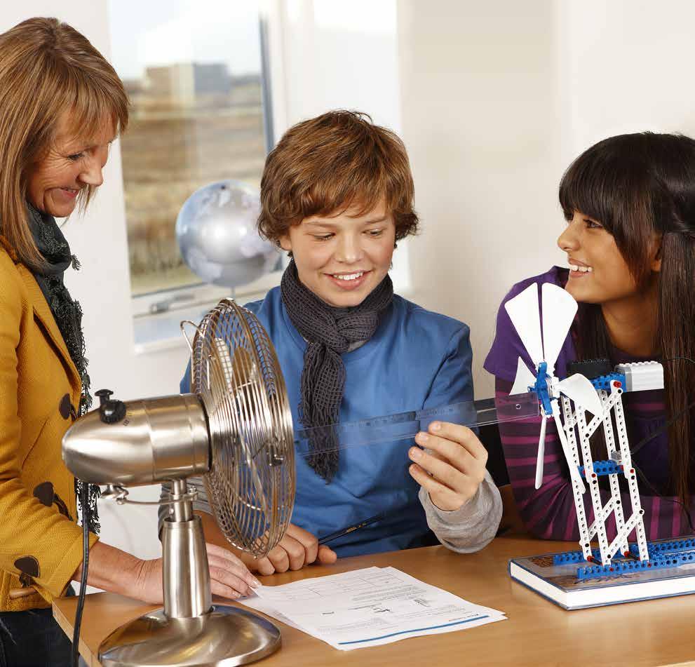
5 Science Energy accumulation Energy conversion Scientific investigation Design and technology Improvements through technological design Assembling components Evaluating Engineering Engineering design Identifying energy Investigating and evaluating variables Mathematics Measuring distance Reading measurements Vocabulary Efficiency Power Voltage Wattage Other materials required Adhesive tape Fan with an effect of at least 40 W Ruler or measuring tape Teacher s Notes 45 Wind Turbine Connect Wind turbines have the ability to convert the wind s kinetic energy into electrical energy. They are used to generate electricity for large utility grids and in isolated locations, such as rural farms. Now build the Wind Turbine and investigate its ability to generate power. Teacher s Notes 46 Introduction Teacher s Notes This section describes key learning areas, hints, questions, answers and vocabulary specific to the activity, and further ideas for investigation. In some cases, additional materials will be necessary for setting up the activities and investigations. These will be listed. Wind Turbine The lessons follow LEGO Education s 4C approach: Connect, Construct, Contemplate and Continue. This approach enables your students to progress naturally through the activities. Connect Connect a new learning experience to those you already have and you add to your knowledge. An initial learning experience is a seed stimulating the growth of new knowledge. Real-life photographs with a short text are provided to help students identify and connect to the chosen activity and the main model. We suggest using the text and photograph as a starting point for a class discussion or draw on your own experiences to provide an engaging introduction to the activity. Please also consider involving current events related to the topic, both near and far, to set the scene for the students. Construct Constructing models engages both hands and minds. Using the Building Instructions, students build models embodying the concepts related to the key learning areas. Suggestions are provided for testing and ensuring each model functions as intended. Contemplate Contemplation provides the opportunity to deepen the understanding of previous knowledge and new experiences. The scientific nature of the activities encourages the students to discuss and reflect on their investigations and adapt ideas to the task at hand. This phase provides the opportunity for you to begin evaluating the learning outcome and progress of individual students. 5
 and power (W) generated by")

6 Name(s): Build the Wind Turbine (Building Instruction booklet 3A and 3B, to page 43 step 18). Test the model s functionality. Loosening bushings can reduce friction Connect the plugs properly by pressing them firmly together 30 cm Six blades and changing the distance First, predict the voltage (V) and power (W) generated by the Wind Turbine at a distance of 30 cm. Then, investigate and read the average voltage and average power generated by the Wind Turbine. Read and record your findings. Remember to reset the Energy Meter before each investigation. Next, turn off the fan and change the distance to 15 cm. Follow the same procedure as described above. Date and subject: 30 cm 15 cm Student Worksheet Make sure to return the joules (J) reading to zero before testing Align the centre of the fan to the centre of the Wind Turbine Choose a suitable power setting on the fan that makes the Wind Turbine rotate at an adequate speed and where the Energy Meters display shows more than 2.0 V on the input reading. Gently turn the blades to get the Wind Turbine started if needed My prediction (V) (W) (V) (W) My average findings (V) (W) (V) (W) 51 Wind Turbine Three blades and changing the distance (Building Instruction booklet 3A and 3B, to page 44 step 1). Turn off the fan and remove three blades from the Wind Turbine. First, predict the voltage (V) and power (W) generated by the Wind Turbine at a distance of 30 cm. Then, investigate and read the average voltage and average power generated by the Wind Turbine. Read and record your findings. Remember to reset the Energy Meter before each investigation. Next, turn off the fan and change the distance to 15 cm. Follow the same procedure as described above. 30 cm 15 cm Student Worksheet My prediction (V) (W) (V) (W) My average findings (V) (W) (V) (W) Identifying variables Identify and write down at least three variables, explaining clearly how these affect the efficiency of the Wind Turbine. 52 Introduction Continue Continued learning is always more enjoyable and creative when it is adequately challenging. Maintaining a challenge and the pleasure of accomplishment naturally inspires the continuation of more advanced work. Extension ideas are therefore provided to encourage the students to change or add features to their models and to investigate further always with the key learning area in mind. This phase allows the students to operate at different speeds and levels conducive to their individual capabilities. Activities challenge the students to creatively apply their knowledge and reflect on model design and the effect of changing certain variables. Student Worksheets Each worksheet has a focused approach following the 4Cs and includes easy-to-read pictorial guidelines. The students can use and explore their models with little teacher assistance. They will be able to predict, investigate, measure, read and record findings, change the models to compare and contrast findings, and draw conclusions. We suggest that students are allowed to work in teams. Each activity challenges students to predict an outcome, to investigate and finally read and record findings. Students should be encouraged to investigate their predictions at least three times to be confident that their results are reliable. When their main findings are recorded, they discuss their results, reflect on them and adapt ideas. Finally, students are challenged to identify variables and explain clearly how these affected the model s efficiency. Wind Turbine The worksheets are an easy-to-use tool for assessing the individual student s level and achievement. They can also form a valuable part of the student s log books. Problem-solving Activities The four Problem-solving Activities focus on applying knowledge of different renewable energy sources, engineering design, communication and team work. They all feature real-life settings describing a problem that needs to be solved. Students are then challenged to solve the problem through their own design. The problem descriptions and the clearly defined design brief are meant to be copied and used by the students. A description of learning objectives, materials needed, and how to progress and evaluate the task at hand is teacher information only! 6

7 Introduction The suggested Problem-solving model solutions included are only meant as guiding principles to the problems posed. Students should always be encouraged to design their own solutions. The Problem-solving Activities are open to be differentiated to fit your current curriculum. How do I handle the Building Instruction booklets? For easy classroom management we suggest storing the Building Instruction booklets in binders so that they are close-at-hand and ready to use at the beginning of each lesson. How much time is needed? A double lesson is ideal to be able to explore, build and investigate in depth most of the extension ideas built into the activities. For the students to make any creative variations of their own, extra time might be needed with the Hydro Turbine and Wind Turbine activities. However, the remaining main models can be built, investigated and explored, and the parts put away again within a single lesson if the students are already experienced LEGO builders. Students can tackle the Problem-solving Activities in a sequence of two double lessons. However, it is worth organizing this time as two or more back-to-back double lessons so that they can immerse themselves in the problem as would a real engineer or designer. Enjoy! LEGO Education 7
8 Curriculum The process of students actively building, exploring, investigating, enquiring and communicating together develops a vast range of benefits. Here is an overview: Science Investigating the collection, storage and transfer of energy; measuring force and speed, and exploring the effect of friction; investigating simple machines, developing scientific fair testing, pursuing purposeful enquiry, predicting and measuring, collating data and drawing conclusions. Design and technology Designing, making (building), testing and evaluating model solutions to match real needs; choosing appropriate materials and processes; exploring systems and subsystems that transform and transfer energy; using two-dimensional instructions to develop technical understanding; identifying technical components to create three-dimensional working models and working collaboratively in a team. Mathematics Using mathematics in the service of science and technology; measuring distance, time and mass, calculating speed (velocity), and weight and efficiency; using graphical means to present predictions and measurements, tabulating and interpreting data, and informally calculating ratios. 8

9 Curriculum Hand Generator Solar Station Science curriculum: Consider evidence from observations, and experiment using distance travelled as a measure of performance Transfer, transformation, storage and dissipation of energy with reference to conversion of kinetic energy to electrical energy Consider evidence from observations, and experiment using average voltage and current as a measure of performance Transfer, transformation, storage and dissipation of energy with reference to conversion of solar energy to electrical energy Design and technology curriculum: Construct with components Investigate and predict effect of gearing systems on generator performance Construct with components Investigate and predict the effect of angles of illumination on Solar Panel performance Mathematics curriculum: Present investigation and prediction data graphically Applications of ratio and proportion Present investigation and prediction data in tabular form Using bearings 9


10 Curriculum Wind Turbine Hydro Turbine Science curriculum: Consider evidence from observations, and experiment using average voltage and power as a measure of performance Transfer, transformation, storage and dissipation of energy with reference to conversion of wind energy to electrical energy Consider evidence from observations, and experiment using joules accumulated as a measure of performance Transfer, transformation, storage and dissipation of energy with reference to conversion of hydro energy to electrical energy Design and technology curriculum: Construct with components Investigate and predict the effect of number of blades and distance from wind source on Wind Turbine performance Construct with components Investigate and predict the effect of number of blades on Hydro Turbine performance Mathematics curriculum: Present investigation and prediction data in tabular form Present investigation and prediction data graphically 10


11 Curriculum Solar Vehicle Boat Pulley Potential / Kinetic Energy Models Science curriculum: Consider evidence from observations, and experiment using speed of movement as a measure of performance Transfer, transformation, storage and dissipation of energy with reference to conversion of solar energy to electrical energy Consider evidence from observations, and experiment using joules expended as a measure of performance Transfer, transformation, storage and dissipation of energy with reference to conversion of electrical energy to potential energy Consider evidence from observations, and experiment to develop explanations concerned with the conversion of potential energy to kinetic energy Design and technology curriculum: Construct with components Investigate and predict the effect of gearing systems on the performance of a Solar Vehicle Construct with components Investigate and predict the effect of pulley systems on the performance of a Boat Pulley hoist Construct with components Mathematics curriculum: Present investigation and prediction data in tabular form Present investigation and prediction data in tabular form Calculate speed Calculate work done and efficiency 11


12 Renewable Energy Renewable Energy All renewable energy sources derive from the Sun. The Sun provides the energy that drives our weather systems and water cycle. It is the prime source of all energy on Earth and it is essential for all forms of life on Earth. Renewable energy is the exploitation of energy from naturally occurring phenomena, such as ocean tides and wind. Renewable energy quickly replaces itself and is generally available as a never-ending source. Sun The Sun has an immense output of energy. Energy from the Sun is called solar energy and is emitted with many ranges of wavelengths. Only a small part of this energy is intercepted by the earth, reaching us, e.g., in the form of visible light. The amount of power in the Sun s rays that reach Earth is measured in watts per square meter. Visible light Wind The Sun s heat is absorbed quicker by land than by the ocean. Warm air over land is less dense then the cool air over the ocean, so it rises and is replaced by the cooler air over the ocean. This movement and changes in temperature is responsible for the movement of air in the atmosphere. Cool air Warm air Water The Sun s heat warms the water in the oceans causing it to evaporate as water vapour into the air. This water vapour condenses into clouds and falls back to the surface as precipitation, e.g., rain and snow. The water flows through streams and rivers back into the oceans, where it can evaporate and begin the cycle over again. Condensation Evaporation Precipitation 12


13 Renewable Energy Solar Energy Solar energy can be captured by, e.g., solar cells. Many solar cells assembled together are called solar panels. Solar panels are designed to capture the suns energy and convert it to more exploitable forms, such as heat or electricity. Technologies linked to solar energy are: Passive solar energy, in which the energy in sunlight is used for light and heat. In passive solar building design the Sun s energy contribution is fully optimised. Active solar water heating systems, in which the Sun s heat energy is transferred to special fluids held in solar collectors. This fluid is pumped through pipes in water tanks and the heat energy transferred to the water. Photovoltaics, in which the energy in visible light from the Sun is converted directly into an electric current by means of solar cells. Using the photoelectric effect, loose electrons in the upper layer of the solar cell are caused to move, thus creating an electric current that can be used to operate an electrical device. Upper layer Junction layer Lower layer 13
14 Renewable Energy Wind Energy Wind energy can be captured by, e.g., wind turbines. Wind turbines are designed to capture the wind s energy and convert it into a more useful form, such as electricity. Technologies linked to wind energy are: Wind turbines with a vertical axis have a rotating axis and blades in a vertical position. They work equally effective irrespective of wind direction. Wind turbines with a horizontal axis have a rotating axis and blades in a horizontal position. They must be faced with respect to wind direction and are the most common type of wind turbine to be found, both onshore and offshore. Wind turbines, whether onshore or offshore, can generate the same amount of power. The key issue of efficiency lies in where the turbines are placed. Offshore wind turbines are often considered more reliable due to the wide open spaces at sea where wind is able to gain energy. Onshore and offshore wind turbines have the same basic parts: tall towers, large turbine blades, axles, gears and a generator. Blade Gear Generator Axle 14

15 Renewable Energy Hydro Energy Hydro energy can be captured by, e.g., hydro turbines. Hydro turbines are designed to capture the energy in moving water and convert it into a more useful form, such as electricity. Technologies linked to hydro energy are: Wave energy, in which the energy in the wave motion of the ocean is captured and used to generate electricity. The waves can be funnelled into a channel or basin to increase their size and hence the available energy. This energy is then used to spin turbines, which in turn drive a generator that generates electricity. Tidal energy, in which the energy in the tidal current is captured and used to generate electricity. A tidal barrage is built across an estuary or inlet. The barrage has gates in it that allow the water to pass through. When the tide has stopped flowing in the gates are closed, creating a large head of water. When the tide flows back, the receding water is channelled through turbines in the gates that generate electricity. Hydroelectric power plants, in which the energy from water in movement is extracted to generate electricity. Most large-scale hydro power plants control the water in reservoirs or dams and channel the water through pipes, also called penstocks, causing the water to flow faster and driving turbines to generate electricity. Dam Penstock Generator Turbine 15
16 Renewable Energy For further discussion in class The following discussion points are optional, but might help provide a potential consolidation and clarification of the Renewable Energy concept. They provide the opportunity for students to share their impressions on what energy is and to gain an understanding of different developments dealing with renewable energy. Depending on the student s personal experience or observations, answers will vary. It is important that different viewpoints and explanations are valued and used to build up an overall understanding that is moving towards scientific understanding. What is energy? Energy is the capacity or ability to do work. Energy is a vital part of our everyday lives. Energy can be stored to be used later and energy can change from one form to another. Energy cannot be made or destroyed as stated in the Law of Conservation of Energy. How is the Sun s energy transferred to Earth and how do we depend on this? The Sun is our primary source of energy. When it is transferring radiation energy to the Earth, e.g., as light waves, it causes such phenomena as plant growth, wind, ocean currents, and the water cycle. How do you define a renewable and a non-renewable energy source? Energy derived from naturally occurring and inexhaustible sources, like solar, wind and hydro, are all renewable energy sources. Energy derived from a finite source, like coal, oil and gas, are non-renewable energy sources. How many domestic electrical appliances have you been in contact with since you woke up? Electricity is the main source of energy in our homes. Electrical energy can be changed to make light energy, heat energy, and sound energy. Students may have been in contact with an electrical alarm or a mobile phone, some may have turned on a light, a radio or the television, some might also have used an electric kettle or opened a refrigerator. Do you know any energy-efficient appliances or other ways we can save on energy? Newer electrical appliances will usually have an energy rating; students can check these. Or alternatively, check some of the school s electrical appliances. Replacing incandescent light bulbs with energy saving light bulbs also saves energy. Other ways of saving energy could be by turning off the lights if the Sun is shining in, by turning off the computer or television instead of switching to standby mode and by simply minimizing electrical needs. Do you know of any examples of how a renewable energy source is being used in your area? It is likely that student s knowledge will vary and might also be conflicting. Here is an interesting opportunity for the class to find out the facts and learn more about the way information can be presented. Information varies according to vested interests. From an activity such as this, the class might draw up a list of the advantages and disadvantages of different renewable energy sources. When listing, they can consider specific social, economic, political and/or environmental interests. 16
17 Potential and Kinetic Energy Energy cannot be made or destroyed as stated in the Law of Conservation of Energy and it can come in a variety of forms. Each form can be categorised as either potential energy or kinetic energy. Potential Energy Potential energy is stored energy due to an objects relative position and mass. Should changes to the objects position occur, the potential energy of the object will increase, decrease, remain constant or be released, in which case it will be converted into other forms of energy. Two forms of potential energy are gravitational potential energy and elastic potential energy. Gravitational potential energy is the energy stored in an object as a result of the Earth s gravitational pull. A ball half way up an inclined plane has gravitational potential energy as a result of gravity trying to pull the ball back down to its original position. How much gravitational potential energy the ball possesses depends on the mass of the ball, its vertical position or height and the gravitational acceleration of the Earth. Did you know? There are several other forms of potential energy, like electrical potential energy and chemical potential energy. In other words, this means that if the ball was moved further up the inclined plane its potential energy would increase. If the ball was moved further down the inclined plane its potential energy would decrease and if the ball was let go its potential energy would be released and converted into kinetic energy as it rolls down. 17
18 Potential and Kinetic Energy Elastic potential energy is the stored energy of an object that is being stretched, squashed or twisted. Sometimes solid materials are shaped especially so that they are good at storing elastic potential energy. This is true for springs and elastic bands. A stretched elastic band has stored elastic potential energy as a result of the elastic band trying to assume its natural shape. Exactly how much stored elastic potential energy there is, will depend on the characteristics of the band and the amount of force it is subjected to. The same applies for a spring. In other words, this means the more you stretch it the more elastic potential energy it will contain. If you let go of the elastic band its potential energy will be released and converted to kinetic energy as the elastic band contracts and returns to its original shape. Kinetic Energy Kinetic energy is the energy a body has by virtue of its motion. Whenever an object is in motion, whether it is vertical, horizontal, and rotational or simply moving from one location to another, it has kinetic energy. The ball that is being held half way up the inclined plane has potential energy but no kinetic energy, as it is not moving. If the ball is released and it started to roll down the inclined plane it would be gaining kinetic energy. How much it gains will depend on its mass and velocity. In other words, this means that a heavier ball rolling down the inclined plane will have more kinetic energy than a lighter ball rolling from the same position. A ball rolling from the top of the inclined plane will be travelling faster by the time it reaches the bottom of the inclined plane than a ball of the same mass released from half way up the inclined plane. It will have more kinetic energy than the slower moving ball of the same mass simply because it is moving faster. 18
19 Potential and Kinetic Energy Teacher s Notes A1 Potential energy is transformed to kinetic energy as the cart rolls down the ramp. The cart has greatest potential energy at its starting point and greatest kinetic energy at the bottom of the ramp. 60 cm 10 cm A2 Addition of mass to the cart constitutes an increase in potential energy. As the cart rolls down the ramp, potential energy is transformed to kinetic energy. The increase of potential energy and kinetic energy makes the cart travel further and faster. 60 cm 10 cm A3 Addition of height to the ramp constitutes a further increase in the potential energy of the cart still with the additional mass. As the cart rolls down the ramp, potential energy is transformed to kinetic energy. The increase of potential energy and kinetic energy makes the cart travel even further and even faster. 60 cm 20 cm 19
20 Potential and Kinetic Energy Teacher s Notes A4 As the handle of the cart is pulled back the elastic band increases its potential energy. As the handle is let go, potential energy is transformed to kinetic energy and the cart moves. A5 Due to the removal of an elastic band, there is a decrease in potential energy, which makes the cart move a shorter distance. As the handle of the cart is pulled back the elastic band increases its potential energy. As the handle is let go, potential energy is transformed to kinetic energy and the cart moves. 20


21 Potential and Kinetic Energy Student Worksheet A1 (Building Instruction booklet I, page 9 step 11). Let the cart roll down the ramp and explain what has happened in terms of potential and kinetic energy. 60 cm 10 cm A2 (Building Instruction booklet I, page 9 step 12). Let the cart roll down the ramp and explain what has changed and what has happened in terms of potential and kinetic energy. 60 cm 10 cm A3 Let the cart roll down the ramp and explain what has changed and what has happened in terms of potential and kinetic energy. 60 cm 20 cm 21
. Pull the handle back as far as it goes. Then let go and see the cart move.")
22 Potential and Kinetic Energy Student Worksheet A4 (Building Instruction booklet I, page 18 step 27). Pull the handle back as far as it goes. Then let go and see the cart move. Explain what has happened in terms of potential and kinetic energy. A5 (Building Instruction booklet I, page 19 step 28). Pull the handle back as far as it goes. Then let go and see the cart move. Explain what has changed and what has happened in terms of potential and kinetic energy. 22


23 LEGO Energy Meter How to get started The Energy Meter consists of two parts: the LEGO Energy Display and LEGO Energy Storage. The Energy Storage fits onto the bottom of the Energy Display. To install the Energy Storage, simply slide it down onto the Energy Display. Energy Display Energy Storage To remove the Energy Storage, press the plastic tab on the back and... press the Energy Storage down to slide it off. 23


24 Energy Meter Element Guide How to get started To install the Energy Storage, simply slide it down onto the Energy Display. To remove the Energy Storage, press the plastic tab located on the rear of the unit and gently press down to slide it off. Disconnect after use, to optimize the lifetime of the Energy Storage Store at room temperature in a clean, dry place away from heat and frost. To charge the Energy Meter: Connect the Energy Meter either to the LEGO Power Functions Battery Box supplied with six new batteries or the LEGO Power Functions Rechargeable Battery Box in order to charge the Energy Storage Turn on the Energy Meter by pressing the green On/Off button, check that the display is on Let the LEGO Power Functions Battery Box or the LEGO Power Functions Rechargeable Battery Box charge the Energy Meter by leaving them connected for three hours or until the display turns off. After this the Energy Storage and thereby the Energy Meter is fully charged To discharge the Energy Meter: Disconnect all wires and other devices from the Energy Meter Press the green On/Off button for 10 seconds until a triangle with an exclamation mark appears blinking with one second intervals on the display Let the Energy Meter remain like this for approximately 1½ hours or until the display turns off. After this the Energy Storage and thereby the Energy Meter is fully discharged If you wish to cancel the discharge, simply press the On/Off button to turn off the Energy Meter. To return to normal mode, turn on the Energy Meter again. For more information see 24


25 Energy Meter Element Guide How it works The Energy Meter can measure, store and release generated energy. Functionality Energy Display LEGO MINDSTORMS Output Port Display Input plug Directional control switch On/Off button Output plug Energy Storage Energy Display MINDSTORMS Output Port For more on how to use the Energy Meter together with LEGO MINDSTORMS, see Directional control switch Use the directional control switch to operate the output function. By turning the switch in either direction with power on you can control the output function. In the middle position, the output function is off. On/Off button Press the On/Off button down once to turn the Energy Meter on and once more to turn it off. Pressing down and holding the On/Off button down for two seconds will reset joules measurement to 0 J. Output plug Connect the E-Motor to the output plug and read the Energy Meter s power output. A minimum of 1 J must be stored before an output can be drawn from the Energy Meter. Input plug Connect the Solar Panel or E-Motor, used as a generator to the input plug and read the Energy Meter measurements. 25
26 Energy Meter Element Guide Display Measurements Input voltage Input current Input wattage Accumulated joules Output voltage Output current Output wattage Accumulated joules The maximum amount of accumulated joules that can be stored is 100 J. The reading of 100 J will start blinking on the display with one second intervals when this maximum is reached. Input voltage will remain measured in the display, but input current and input wattage will go to zero. The output measurements will depend on the load applied. Pressing down and holding the On/ Off button for two seconds will reset the joules measurement to 0 J. Please notice that this is not an indication of the charged status of the Energy Storage. Blinking lightning symbol A lightning symbol appears blinking with one second intervals on the display, when one of two possible situations have occurred: If the number of joules remains the same, then you should be able to continue your activity, but the Energy Storage power level is low and you should soon charge the Energy Meter. The Energy Storage should be charged before each lesson. If the number of joules reset to 0 J and output voltage goes to zero, then the Energy Meter has been overloaded and must be recharged. Do not overload the Energy Meter. Constant lightning symbol A constant lightning symbol appears on the Energy Meter display when the Energy Storage needs to be charged. Error A triangle with an exclamation mark appears on the display when there is an error on the Energy Storage. Measurements are not valid. Remove the Energy Storage, check the connecting parts and see if they need cleaning. Reconnect the Energy Storage to the Energy Display and charge the Energy Meter. If the error triangle reappears, replace with a new Energy Storage. 26
27 Energy Meter Element Guide Energy Storage The Energy Storage stores the energy you have generated. Measurements on the Energy Display are not valid when disconnected from the Energy Storage. The lifespan of the Energy Storage depends heavily on the way it is used, maintained and stored. Store the Energy Storage at room temperature in a clean, dry place away from heat. Heat, frost and long discharge periods can significantly shorten the expected lifespan of the Energy Storage. Disconnect the Energy Storage after use. It is necessary to recharge the Energy Storage after a long storage period. Technical Specifications The Energy Meter will display measurements in the range of: 0.0 V to 9.9 V, input voltage A to A, input current P = V x I, P = input wattage 0 J to 100 J, accumulated joules 0.0 V to 9.9 V, output voltage A to A, output current P = V x I, P = output wattage Refresh Rate and Averaging Measurements Display measurements are refreshed every 0.5 seconds; they are calculated by averaging the measurements at equal intervals of 100 per 0.5 second. Depending on the input, this should give fairly constant and easily identifiable measurements. Take good care of your Energy Meter Do not bend or push hard on it or elements connected to it Do not step on or otherwise place heavy weights on it Do not drop it Do not short circuit it Do not exceed the maximum 10 V supply voltage Do not overload the Energy Meter as this will cause it to discharge It is not waterproof Store at room temperature in a clean, dry place away from heat and frost The Energy Storage should be charged before each lesson 27


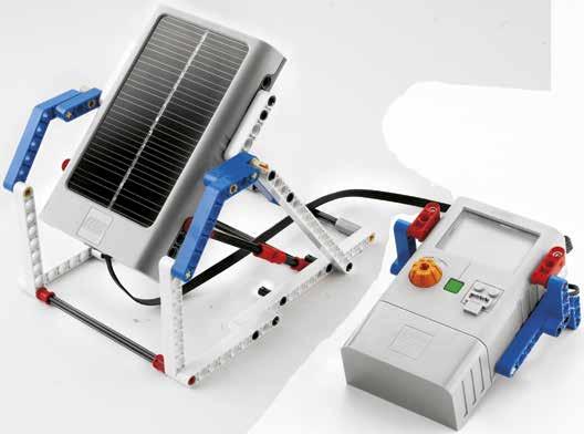
28 LEGO Solar Panel How it works Solar Panels can convert solar energy into electrical energy. The ideal light source is full natural sunlight. When incandescent light bulbs are used, be cautious, they produce a lot of heat and the light bulb should only be on for short periods at a time. Also keep the light bulb at a reasonable distance from the Solar Panel (at least 8 cm) and increase the distance or turn off the light bulb if the Solar Panel gets hot. Do not use energy saving light bulbs; the light they emit is insufficiently bright. An energy saving light bulb emits a very low amount of light in the IR range nm. Functionality Solar Panel Output plug Solar Panel The Solar Panel consists of fourteen solar cells and four diodes, with a total voltage output of approximately 7 V. Output plug The output plug lets you transfer the energy from the Solar Panel to elements like the LEGO Energy Meter or the E-Motor. Technical Specifications With optimal light settings the Solar Panel provides sufficient power to operate the Energy Meter and E-Motor. It delivers: 6.5 V, 100 ma > at 100,000 lux, daylight outdoors 6.5 V, 50 ma > at 50,000 lux, indoor sunlight 5 V, 4 ma > at 2,000 lux, 60 W incandescent bulb positioned 25 cm from the Solar Panel 5 V, 20 ma > at 10,000 lux, 60 W incandescent bulb positioned 8 cm from the Solar Panel 28
29 Solar Panel Element Guide Take good care of your Solar Panel Do not bend or push hard on it or elements connected to it Do not step on or otherwise place heavy weights on it Do not drop it Do not short circuit it Keep the light bulb at a reasonable distance from the Solar Panel (at least 8 cm) and increase the distance or turn off the light bulb if the Solar Panel gets hot It is not waterproof Store at room temperature in a clean, dry place away from heat and frost 29

30 E-Motor How it works The E-Motor is a 9 V motor with an internal gearbox. The E-Motor can also work as a generator of electrical energy. Functionality Input/output plug Axle hole Axle hole Insert an axle and make it turn to use the E-Motor as either a motor or a generator. Input/output plug The input/output plug allows you to transfer electrical energy from the E-Motor to elements like the Energy Meter and LED Lights, or to transfer electrical energy to the E-Motor from elements like the Solar Panel or the Energy Meter. Technical Specifications Without load its rotation speed is around 800 rotations per minute and it delivers: Maximum torque of 4.5 N/cm 9 V motor 9.5:1 gearing 20 cm wire Take good care of your E-Motor Do not bend or push hard on it or elements connected to it Do not step on or otherwise place heavy weights on it Do not drop it Do not short circuit it Do not exceed the maximum 9 V supply voltage Do not leave it in a stalled condition It is not waterproof Store at room temperature in a clean, dry place away from heat and frost 30
31 Teacher s Notes Hand Generator Science Energy accumulation Energy consumption Energy conversion Scientific investigation Design and technology Improvements through technological design Assembling components Evaluating Using mechanisms gears Engineering Engineering design Identifying energy Investigating and evaluating variables Mathematics Graphing Measuring distance Reading measurements Timing Vocabulary Efficiency Distance Joules Work Other materials required Graph paper Ruler or measuring tape Stopwatch or timer 31

32 Hand Generator Teacher s Notes Connect Generators have the ability to convert mechanical energy into electrical energy. The human body can operate a generator by turning the handle. The faster we turn the handle the more electricity we generate. Now build the Hand Generator and investigate its ability to generate power. 32


33 3 Hand Generator Teacher s Notes Construct Build the Hand Generator and the Joule Jeep (Building Instruction booklet 1A and 1B, to page 15 step 16). 1A Test the model s functionality. Loosening bushings can reduce friction Connect the plugs properly by pressing them firmly together Make sure to return the joules (J) reading to zero before testing Test setting Mark a start line for your Joule Jeep 33
34 Hand Generator Teacher s Notes Contemplate Turn and go The task requires students to investigate how many joules (J) the Hand Generator can accumulate after a time period of 60 seconds and see how far these joules can power the Joule Jeep. Did you know? An idler gear changes the direction of rotation, but does not affect the output speed. First, have students graph their prediction in a system of coordinates showing how many joules they will accumulate after a time period of 60 seconds. Then, have students investigate how many joules they can accumulate by turning the handle of the Hand Generator during a period of 60 seconds. Have them read and record their findings at 10 second intervals and have them graph their findings in the same system of coordinates as their prediction. Next, have students find out how far the Joule Jeep can run on the amount of accumulated joules. Hint Reset the Energy Meter before each investigation. Findings will vary; students will see that the distance travelled by the Joule Jeep will vary depending on the amount of accumulated joules. Have students reflect on their investigations by asking questions, such as: Which factors did you base your predictions on? Can you explain your findings? Can you identify a pattern or trend in the findings? For a given time, the amount of accumulated joules is proportional to the speed of turning the handle. How did you make sure that your findings were scientifically valid? Students need to investigate several times to make sure findings are consistent and that the Joule Jeep starts and runs from the same spot and on the same track surface. 34
35 Hand Generator Teacher s Notes Continue Gearing up (Building Instruction booklet 1A and 1B, to page 16 step 1). The task requires students to investigate how many joules (J) the rebuilt Hand Generator can accumulate after a time period of 60 seconds and then see how far these joules can power the Joule Jeep. First, have students rebuild the Hand Generator s gearing. Then, based on their knowledge of specific characteristics of gears, have them graph their prediction in a system of coordinates showing how many joules they will be able to accumulate over a time period of 60 seconds. Then, have students investigate how many joules they can accumulate by turning the handle of the Hand Generator during a period of 60 seconds. Have them read and record their findings at 10 second intervals and have them graph their findings in the same system of coordinates as their prediction. Did you know? The unit for the energy producing potential in food is calories (cal). One calorie is generally assumed to be 4.2 J. Hint Reset the Energy Meter before each investigation. Next, have students find out how far the Joule Jeep can run on the amount of accumulated joules. Findings will vary, but a significant increase in the amount of joules accumulated will be seen. Ideally, students should predict a 60% increase in the amount of joules accumulated. How far the Joule Jeep will travel will vary depending on the amount of accumulated joules. Identifying variables Have students identify and write down at least three variables, explaining clearly how these affect the efficiency of the Hand Generator and the Joule Jeep. Some factors could include the effects of changing the gearing, the length of the handle, the speed with which the handle is turned, the strength and stamina of the person turning the handle and the structural stability of the Hand Generator. The Joule Jeep s efficiency is influenced by its weight, gearing, friction and the track surface. 35
 reading to zero before testing Mark a start line for your Joule")

36 Student Worksheet Hand Generator Name(s): Date and subject: Build the Hand Generator and the Joule Jeep (Building Instruction booklet 1A and 1B, to page 15 step 16). Test the models functionality. Loosening bushings can reduce friction Connect the plugs properly by pressing them firmly together Make sure to return the joules (J) reading to zero before testing Mark a start line for your Joule Jeep Turn and go First, predict how many generated joules (J) you will be able to accumulate by turning the handle of the Hand Generator after a time period of 60 seconds (sec.). J Graph your prediction in a system of coordinates as illustrated opposite. Then, investigate the amount of joules accumulated at 10 second intervals. Read and record your findings. Graph your findings in the same system of coordinates as your prediction. Remember to reset the Energy Meter before each investigation. Next, mark a starting line for your Joule Jeep and find out how far the Joule Jeep can run on the amount of accumulated joules. My Joule Jeep travelled a distance of Prediction Findings sec. 10 sec. 20 sec. 30 sec. 40 sec. 50 sec. 60 sec. My prediction (J) (J) (J) (J) (J) (J) My findings (J) (J) (J) (J) (J) (J) 36


37 Hand Generator Student Worksheet Gearing up (Building Instruction booklet 1A and 1B, to page 16 step 1). First, rebuild the Hand Generator s gearing. Look carefully to see what difference the new gearing will make to the speed. Predict how many generated joules (J) you will be able to accumulate by turning the handle of the Hand Generator after a time period of 60 seconds (sec.). Graph your prediction in a system of coordinates as illustrated opposite. Then, investigate the amount of joules accumulated at 10 second intervals. Read and record your findings. J Graph your findings in the same system of coordinates as your prediction. Remember to reset the Energy Meter before each investigation. Next, mark a starting line for your Joule Jeep and find out how far the Joule Jeep can run on the amount of accumulated joules. My Joule Jeep travelled a distance of sec. Prediction Findings 10 sec. 20 sec. 30 sec. 40 sec. 50 sec. 60 sec. My prediction (J) (J) (J) (J) (J) (J) My findings (J) (J) (J) (J) (J) (J) Identifying variables Identify and write down at least three variables, explaining clearly how these affect the efficiency of the Hand Generator and Joule Jeep. 37
38 Teacher s Notes Solar Station Science Energy conversion Energy transfer Scientific investigation Design and technology Improvements through technological design Assembling components Evaluating Engineering Engineering design Identifying energy Investigating and evaluating variables Mathematics Angles Graphing Measuring distance Reading measurements Vocabulary Current Perpendicular to LEGO Solar Panel Voltage Other materials required A 60W incandescent light bulb, high performance halogen emitters or any other light source that emits a high amount of IR spectra > 800 nm Lamp with parabolic reflector Ruler or measuring tape Tin foil 38

39 Solar Station Teacher s Notes Connect Solar panels have the ability to convert solar energy into electrical energy. They are used to generate electricity for large utility grids, for satellites in space and in isolated locations for small communities or single homes. Now build the Solar Station and investigate its ability to generate power. 39
 reading to zero before testing Test setting Position the Solar")
40 23 Solar Station Teacher s Notes Construct Build the Solar Station (Building Instruction booklet 2A and 2B, to page 30 step 15). 2A Test the model s functionality. Loosening bushings can reduce friction Connect the plugs properly by pressing them firmly together Make sure to return the joules (J) reading to zero before testing Test setting Position the Solar Station at a distance of 15 cm from the light source A 60W incandescent light bulb, high performance halogen emitters or any other light source that emits a high amount of IR spectra > 800 nm. Place the Solar Panel under the centre of the light source. Optimally the lamps diameter should cover the LEGO Solar Panel and have a parabolic reflector To help students measure the distance of the bulb in the lamp to the Solar Panel, it is helpful to make a mark on the lamp casing, level with the centre of the light bulb 15 cm Warning! Heat can damage the Solar Panel. Keep a distance of at least 8 cm from the Solar Panel to the light source at all times. Make sure students handle light bulbs with great care! 40
 readings.")
41 Solar Station Teacher s Notes Contemplate Changing angles The task requires students to investigate how changing the angle of the Solar Panel to the light source will affect the average voltage (V) and average current (A) readings. First, have students predict the average voltage and current of the Solar Station when positioned perpendicular to the light source (see opposite) at a distance of 15 cm. Then, have students investigate the average voltage and current of the Solar Station when positioned horizontally. Have them read and record their findings. Make sure students let the Energy Meter units settle before carrying out the readings. Horizontal Hint Reset the Energy Meter before each investigation. Next, have students follow the same procedure for the Solar Station in a diagonal position and a vertical position to the light source (see opposite). Findings will vary depending on the light source used, the amount of surrounding light in the room and the colour of the surface where the Solar Station is placed. Students will see that maximum power is produced when the incident light beam is perpendicular to the Solar Panels surface. Have students reflect on their investigations by asking questions such as: Which factors did you base your predictions on? Can you explain your findings? Can you identify a pattern or trend in the findings? Diagonal Hint The Energy Meter display must show an input reading of more than 2.0 V to show readings on the display. The intensity of the light is at a maximum when the light source is perpendicular to the Solar Panel. As the intensity of light on the surface of the Solar Panel decreases, the voltage, and in particular the current, also decreases. Vertical How did you make sure that your findings were scientifically valid? Students need to investigate several times to make sure findings are consistent, that the Solar Station always stays in the same position and at the same distance from the light source. 41
, the light source conditions and the distance to the light source.")

42 Solar Station Teacher s Notes Continue Identifying variables Have students identify and write down at least three variables, explaining clearly how these affect the Solar Station s efficiency. Hint Reset the Energy Meter before each investigation. Some factors could include the size of the area exposed (e.g. partially covering some of the Solar Station), the light source conditions and the distance to the light source. Optimizing variables Based on the variables students have identified, have them optimise the Solar Station to maximise the amount of power (W) produced. Have students record findings and describe which variables have been altered. We suggest increasing the wattage of the lamp; one could also use a mirror to reflect the light onto the Solar Station and another underneath the Solar Station to reflect the light back. Instead of a mirror, wrap tin foil around the lid of the basis set as a reflector. Optional Have students simulate different weather and landscape situations to investigate the increase or decrease in the Solar Station s ability to generate power. Have students describe their simulations, the setup and key measurements. Hint You can simulate clouds by covering the Solar Station with tissue paper or other light-absorbent materials. 42
 reading to zero before testing Position the LEGO Solar Panel")

43 Student Worksheet Solar Station Name(s): Date and subject: Build the Solar Station (Building Instruction booklet 2A and 2B, to page 30 step 15). Test the model s functionality. Loosening bushings can reduce friction Connect the plugs properly by pressing them firmly together Make sure to return the joules (J) reading to zero before testing Position the LEGO Solar Panel under the centre of the light source 15 cm Changing angles First, predict the average voltage (V) and the average current (A) readings of the Solar Station when positioned perpendicular to the light source at a distance of 15 cm. Remember to reset the Energy Meter before each investigation. Then, investigate the average voltage and current of the Solar Station in this horizontal position. Make sure to let the Energy Meter units stabilize before carrying out the readings. Read and record your findings. Next, follow the same procedure for the Solar Station in a diagonal position and a vertical position to the light source. Horizontal Diagonal Vertical My prediction of V (V) (V) (V) My prediction of A (A) (A) (A) My average findings of V (V) (V) (V) My average findings of A (A) (A) (A) 43
44 Solar Station Student Worksheet Identifying variables Identify and write down at least three variables, explaining clearly how these affect the efficiency of the Solar Station. Optimizing variables Based on the variables identified, optimise the Solar Station to maximize the power generated. Explain which variables are altered, their effect and record findings. Note them on this worksheet and show the set up, e.g. by taking a photograph or by sketching. Remember to reset the Energy Meter before each investigation. 44
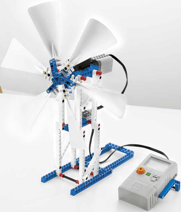
45 Teacher s Notes Wind Turbine Science Energy accumulation Energy conversion Scientific investigation Design and technology Improvements through technological design Assembling components Evaluating Engineering Engineering design Identifying energy Investigating and evaluating variables Mathematics Measuring distance Reading measurements Vocabulary Efficiency Power Voltage Wattage Other materials required Adhesive tape Fan with an effect of at least 40 W Ruler or measuring tape 45

46 Wind Turbine Teacher s Notes Connect Wind turbines have the ability to convert the wind s kinetic energy into electrical energy. They are used to generate electricity for large utility grids and in isolated locations, such as rural farms. Now build the Wind Turbine and investigate its ability to generate power. 46
47 35 Wind Turbine Teacher s Notes Construct Build the Wind Turbine (Building Instruction booklet 3A and 3B, to page 43 step 18). 3A Test the model s functionality. Loosening bushings can reduce friction Connect the plugs properly by pressing them firmly together Make sure to return the joules (J) reading to zero before testing 30 cm Test setting Align the centre of the fan to the centre of the Wind Turbine with a distance of 30 cm between them Choose a suitable power setting on the fan that makes the Wind Turbine rotate at an adequate speed and where the Energy Meter s display shows more than 2.0 V on the input reading. The fan must have an effect of at least 40 W To find the optimal set up, look at the Energy Meter readings as an indicator of which position generates the most power Stability is important; one could choose to use adhesive tape or books to hold the Wind Turbine in place Students can gently turn the blades to get the Wind Turbine started if needed Warning! Fans are potentially dangerous. Make sure that students handle them with great care! Ensure that students turn the fan off when changing the number of blades during the activity. 47
48 Wind Turbine Teacher s Notes Contemplate Six blades and changing the distance The task requires students to investigate the performance of the Wind Turbine at different settings and to read and record the average voltage (V) and the average power (W) generated. First, have students predict the voltage and power generated by the Wind Turbine at a distance of 30 cm. Then, have students investigate and read the average voltage and average power generated by the Wind Turbine. Have them read and record their findings. Next, have students turn off the fan and change the distance to 15 cm. Follow the same procedure as described above. Did you know? Wind turbines can rotate around both horizontal and vertical axis. Horizontal-axis wind turbines (HAWT) are most commonly used. Hint Reset the Energy Meter before each investigation. Findings will vary; students will see that power increases when the Wind Turbine is moved closer to the wind source. Have students reflect on their investigations by asking questions such as: Which factors did you base your predictions on? Can you explain your findings? Can you identify a pattern or trend in the findings? The closer the wind source is to the Wind Turbine, the more power that is generated. How did you make sure that your findings were scientifically valid? Students need to investigate several times to make sure findings are consistent and that the Wind Turbine stays in the same position and at the same distance from the fan. 48
49 Wind Turbine Teacher s Notes Continue Three blades and changing the distance (Building Instruction booklet 3A and 3B, to page 44 step 1). The task requires students to investigate the performance of the Wind Turbine at different settings and to read and record the average voltage (V) and the average power (W) generated. Hint Have students turn off the fan before changing the number of blades on the Wind Turbine. First, have students predict the voltage and power generated by the Wind Turbine at a distance of 30 cm. Then, have students investigate and read the average voltage and average power generated by the Wind Turbine. Have them read and record their findings. Hint Reset the Energy Meter before each investigation. Next, have students turn off the fan and change the distance to 15 cm. Follow the same procedure as described above. Findings will vary; students will see that power increases when the Wind Turbine is moved closer to the wind source. Students will find that the Wind Turbine with six blades generates more power. Identifying variables Have students identify and write down at least three variables, explaining clearly how these affect the Wind Turbine s efficiency. Some factors could include the effect of changing the number of blades used, the angle between the centre of the fan and Wind Turbine and the force of the wind. The efficiency of the E-Motor (e.g. the turbine) plays a major role in the overall efficiency of the Wind Turbine. 49
50 Wind Turbine Teacher s Notes Optional Have students simulate different landscapes to investigate the increase or decrease in the Wind Turbines ability to generate power. You can simulate a landscape feature by e.g. placing a book between the fan and the Wind Turbine. Have students describe their simulations, the setup and key measurements, e.g. the height and the distance between the fan and the Wind Turbine. 50
 reading to zero before testing Align the centre of the fan to the")
51 Student Worksheet Wind Turbine Name(s): Date and subject: Build the Wind Turbine (Building Instruction booklet 3A and 3B, to page 43 step 18). Test the model s functionality. Loosening bushings can reduce friction Connect the plugs properly by pressing them firmly together Make sure to return the joules (J) reading to zero before testing Align the centre of the fan to the centre of the Wind Turbine Choose a suitable power setting on the fan that makes the Wind Turbine rotate at an adequate speed and where the Energy Meters display shows more than 2.0 V on the input reading. Gently turn the blades to get the Wind Turbine started if needed 30 cm Six blades and changing the distance First, predict the voltage (V) and power (W) generated by the Wind Turbine at a distance of 30 cm. Then, investigate and read the average voltage and average power generated by the Wind Turbine. Read and record your findings. Remember to reset the Energy Meter before each investigation. Next, turn off the fan and change the distance to 15 cm. Follow the same procedure as described above. 30 cm 15 cm My prediction (V) (W) (V) (W) My average findings (V) (W) (V) (W) 51
 and power (W) generated by the Wind Turbine at a distance of 30 cm. Then, investigate and read the average voltage and average power generated by the Wind Turbine.")
52 Wind Turbine Student Worksheet Three blades and changing the distance (Building Instruction booklet 3A and 3B, to page 44 step 1). Turn off the fan and remove three blades from the Wind Turbine. First, predict the voltage (V) and power (W) generated by the Wind Turbine at a distance of 30 cm. Then, investigate and read the average voltage and average power generated by the Wind Turbine. Read and record your findings. Remember to reset the Energy Meter before each investigation. Next, turn off the fan and change the distance to 15 cm. Follow the same procedure as described above. 30 cm 15 cm My prediction (V) (W) (V) (W) My average findings (V) (W) (V) (W) Identifying variables Identify and write down at least three variables, explaining clearly how these affect the efficiency of the Wind Turbine. 52
53 Teacher s Notes Hydro Turbine Science Energy accumulation Energy conversion Scientific investigation Design and technology Improvements through technological design Assembling components Evaluating Engineering Engineering design Identifying energy Investigating and evaluating variables Mathematics Graphing Measuring distance Reading measurements Timing Vocabulary Joules Water pressure Other materials required Adhesive tape Enough water pressure to read at least 2.0 V on the Energy Meter input reading Graph paper Stopwatch or timer Tea towels or tissue paper to dry LEGO elements 53

54 Hydro Turbine Teacher s Notes Connect Hydro turbines have the ability to convert the kinetic energy of moving water into electrical energy. They are used to generate electricity for large utility grids and in isolated locations for small communities or for single homes. Now build the Hydro Turbine and investigate its ability to generate power. 54

55 4A 3 Hydro Turbine Teacher s Notes Construct Build the Hydro Turbine (Building Instruction booklet 4A and 4B, to page 20 step 30). Test the model s functionality. Loosening bushings can reduce friction Connect the plugs properly by pressing them firmly together Make sure to return the joules reading to zero before testing Test setting Position the Hydro Turbine at an appropriate distance from the tap Choose a suitable, constant water pressure that shows at least 2.0 V on the Energy Meter s input reading To find the optimal set up, look at the Energy Meter readings as an indicator of which position generates the most power When the pressure point is found, mark the tap handles position with a piece of adhesive tape Have tea towels or tissue paper close at hand to dry LEGO elements Students can gently turn the blades to get the Hydro Turbine started if needed Warning! Make sure that the Energy Meter and the E-Motor are protected as best you can from water spray, they are not waterproof. Additional protection from a plastic bag or cling film might be appropriate. 55
56 Hydro Turbine Teacher s Notes Contemplate Accumulating joules The task requires students to investigate how many joules (J) the Hydro Turbine can accumulate after a time period of 120 seconds. Hint The Energy Meter display must show more than 2.0 V on the input reading. First, have students predict how many joules the Hydro Turbine will accumulate after a time period of 120 seconds at 20 second intervals. Then, have students graph their prediction in a system of coordinates of how many joules the Hydro Turbine will accumulate after a time period of 120 seconds at 20 second intervals. Next, have students investigate how many joules they can accumulate after a period of 120 seconds. Have them read and record their findings at 20 second intervals and have them graph their findings in the same system of coordinates as their prediction. Hint Reset the Energy Meter before each investigation. Before taking any readings, make sure students let the Hydro Turbine run for a while to pick up speed. Findings will vary depending on the water power device available, students will see that the amount of joules accumulated is proportional to the water pressure and time period used. Have students reflect on their investigations by asking questions such as: Which factors did you base your predictions on? Can you explain your findings? Can you identify a pattern or trend in the findings? The amount of joules accumulated is proportional to the water pressure and time period. How did you make sure that your findings were scientifically valid? Students need to investigate several times to make sure findings are consistent, that the Hydro Turbine turns either clockwise or anticlockwise each time, that the water hits the blades in the same spot in every investigation and that the Hydro Turbine always stays in the same position and at the same distance from the water supply. 56
57 Hydro Turbine Teacher s Notes Continue Changing the number of blades (Building Instruction booklet 4A and 4B, to page 22 step 2). The task requires students to investigate how many joules (J) the Hydro Turbine can accumulate after a time period of 120 seconds, with only three blades attached. First, have students predict how many joules the Hydro Turbine will accumulate after a time period of 120 seconds at 20 second intervals. Did you know? The power available from any water power device depends on three variables: the height that the water supply is above the turbine, also called the head, the flow rate and gravity. Then, have students graph their prediction in a system of coordinates of how many joules the Hydro Turbine will accumulate after a time period of 120 seconds at 20 second intervals. Next, have students investigate how many joules they can accumulate after a period of 120 seconds. Have them read and record their findings at 20 second intervals and have them graph their findings in the same system of coordinates as their prediction. Hint Reset the Energy Meter before each investigation and remember to keep the same water pressure as before. Before taking any readings, make sure students let the Hydro Turbine run for a while to pick up speed. Findings will vary depending on the water power device available, students will see that the amount of joules accumulated is proportional to the water pressure and time period used. Students will also see that a lesser amount of joules are accumulated when the Hydro Turbine only has three blades attached. Identifying variables Have students identify and write down at least three variables, explaining clearly how these affect the Hydro Turbine s efficiency. Some factors could include the effects of changing the diameter of the Hydro Turbine, the area and number of blades used, the angle and position at which the blades catch the flow of water, and the condition of the water flow. 57
 reading to zero before testing Choose a suitable, constant water")
58 Student Worksheet Hydro Turbine Name(s): Date and subject: Build the Hydro Turbine (Building Instruction booklet 4A and 4B, to page 20 step 30). Test the model s functionality. Loosening bushings can reduce friction Connect the plugs properly by pressing them firmly together Make sure to return the joules (J) reading to zero before testing Choose a suitable, constant water pressure that shows at least 2.0 V on the Energy Meters input reading When the pressure point is found, mark the tap handles position with a piece of adhesive tape Gently turn the blades to get the Hydro Turbine started if needed Accumulating joules First, predict how many joules (J) the Hydro Turbine will accumulate after a time period of 120 seconds (sec.) at 20 second intervals. J Then, graph your prediction in a system of coordinates, as illustrated opposite. Next, investigate how many joules can be accumulated after a period of 120 seconds. Read and record your findings at 20 second intervals. Graph your findings in the same system of coordinates as your prediction. Remember to reset the Energy Meter before each investigation. Prediction Findings sec. 20 sec. 40 sec. 60 sec. 80 sec. 100 sec. 120 sec. My prediction (J) (J) (J) (J) (J) (J) My findings (J) (J) (J) (J) (J) (J) 58


59 Hydro Turbine Student Worksheet Changing the number of blades (Building Instruction booklet 4A and 4B, to page 22 step 2). Change the number of blades on the Hydro Turbine by removing three blades and follow the same procedure as previously. Keep the same water pressure as before. First, predict how many joules (J) the Hydro Turbine will accumulate after a time period of 120 seconds (sec.) at 20 second intervals. Then, graph your prediction in a system of coordinates, as illustrated opposite. Next, investigate how many joules can be accumulated after a period of 120 seconds. Read and record your findings at 20 second intervals. Graph your findings in the same system of coordinates as your prediction. Remember to reset the Energy Meter before each investigation. J sec. Prediction Findings 20 sec. 40 sec. 60 sec. 80 sec. 100 sec. 120 sec. My prediction (J) (J) (J) (J) (J) (J) My findings (J) (J) (J) (J) (J) (J) Identifying variables Identify and write down at least three variables, explaining clearly how these affect the efficiency of the Hydro Turbine. 59
60 Teacher s Notes Solar Vehicle Science Energy conversion Energy transfer Forces and motion Scientific investigation Design and technology Improvements through technological design Assembling components Evaluating Using mechanisms gears, wheels and axles Engineering Engineering design Identifying energy Investigating and evaluating variables Mathematics Calculating speed Measuring distance Reading measurements Timing Vocabulary Efficiency LEGO Solar Panel Speed Other materials required A smooth flat track surface at least 150 cm long A 60 W incandescent light bulb, high performance halogen emitters or any other light source that emits a high amount of IR spectra > 800 nm Lamps with parabolic reflectors Masking tape and marker for start and stop line Ruler or measuring tape Stopwatch or timer 60

61 Solar Vehicle Teacher s Notes Connect Solar vehicles use the ability of solar panels to convert solar energy into electrical energy. The motor has the ability to convert electrical energy into mechanical energy and move the vehicle. Now build the Solar Vehicle and investigate its speed with different gear ratios and wheel size. 61
62 5A 23 Solar Vehicle Teacher s Notes Construct Build the Solar Vehicle (Building Instruction booklet 5A and 5B, to page 38 step 24). Test the model s functionality. Loosening bushings can reduce friction Connect the plugs properly by pressing them firmly together Test setting Position the LEGO Solar Panel at an adequate distance from the light source A 60 W incandescent light bulb, high performance halogen emitters or any other light source that emits a high amount of IR spectra > 800 nm Place the Solar Panel under the centre of the light source. Optimally the lamps diameter should cover the LEGO Solar Panel and have a parabolic reflector To set up an illuminated test track, place several identical light bulbs / lamps at the same height above the 100 cm test track To help students measure the distance of the bulb in the lamp to the Solar Panel, it is helpful to make a mark on the lamp casing, level with the centre of the light bulb Mark a start line and finish line 100 cm apart on a smooth flat surface Students can gently push the Solar Vehicle forward to get it started if needed 100 cm Warning! Heat can damage the Solar Panel. Keep a distance of at least 8 cm from the Solar Panel to the light source at all times. Make sure students handle light bulbs with great care! 62


63 Solar Vehicle Teacher s Notes Contemplate Travelling with different gear ratios The task requires students to investigate the speed of the Solar Vehicle travelling the track with different gearings and two large rear wheels. Did you know? Gear ratio can be found by comparing the number of teeth on the gears. First, have students predict with which speed the Solar Vehicle will travel the track with a gearing of 5:1. Then, have students investigate the speed of the Solar Vehicle travelling the track with a gearing of 5:1. Calculate the speed and record your findings. Use this formula, where speed is measured in meters per second: Speed = Distance travelled Time taken Findings will vary depending on the light source and the influence of friction. Next, rebuild the Solar Vehicle and have students follow the same procedure for the new Solar Vehicle with a gearing of 3:1. (Building Instruction booklet 5A and 5B, to page 42 step 4). Findings will vary, students will see that the Solar Vehicle with a gearing of 3:1, travels fastest. Have students reflect on their investigations by asking questions such as: Which factors did you base your predictions on? Can you explain your findings? Can you identify a pattern or trend in the findings? The 3:1 gearing travels fastest because of the gear ratio. How did you make sure that your findings were scientifically valid? Students need to investigate several times to make sure findings are consistent and that the Solar Panel stays in the same position and at the same distance from the light source. 63


64 Solar Vehicle Teacher s Notes Continue Travelling with smaller wheels (Building Instruction booklet 5A and 5B, to page 44 step 6). The task requires students to investigate the speed of the Solar Vehicle travelling the track with a gearing of 3:1 and with two small rear wheels. First, have students predict with which speed the Solar Vehicle will travel the track with a gearing of 3:1 and three identical small wheels. Then, have students investigate the speed of the Solar Vehicle travelling the track with a gearing of 3:1 and three identical small wheels. Calculate the speed and record your findings. Findings will vary depending on the light source and friction. Next, have students look carefully at their findings and compare this new arrangement of the Solar Vehicle to the prior test findings, where the Solar Vehicle had a 3:1 gearing and two larger rear wheels. Findings will vary, but the Solar Vehicle with the large rear wheels will travel the distance fastest, even though the axle speed is the same, due to the larger circumference of the larger wheels. Identifying variables Have students identify and write down at least three variables, explaining clearly how these affect the Solar Vehicles efficiency. Did you know? The circumference of the small wheel is 9.6 cm. The circumference of the large wheel is 13.6 cm Some factors could include the effects of changing the amount of light on the Solar Panel, friction, wheel diameter, balance and changing the weight of the Solar Vehicle. Optional Have students optimise conditions for the Solar Vehicle. 64


.")
65 Student Worksheet Solar Vehicle Name(s): Date and subject: Build the Solar Vehicle (Building Instruction booklet 5A and 5B, to page 38 step 24). Test the model s functionality. Loosening bushings can reduce friction Connect the plugs properly by pressing them firmly together Position the Solar Panel at an adequate distance from the light source, but at least 8 cm apart because of heat Place the Solar Panel under the centre of the light source Mark a start line and finish line 100 cm apart on a smooth flat surface Gently push the Solar Vehicle forward to get it started if needed 100 cm Travelling with different gear ratios First, predict with which speed the Solar Vehicle will travel the track with a gearing of 5:1. Then, investigate with which speed the Solar Vehicle will travel the track with the gearing of 5:1, where speed is measured in meters per second (m/s), by using this formula: Next, rebuild the Solar Vehicle and follow the same procedure for the new Solar Vehicle with a gearing of 3:1. (Building Instruction booklet 5A and 5B, to page 42 step 4). Speed = Distance travelled Time taken My prediction sec. sec. My findings sec. sec. My calculations (m/s) (m/s) 65
66 Solar Vehicle Student Worksheet Travelling with smaller wheels (Building Instruction booklet 5A and 5B, to page 44 step 6). First, predict with which speed the Solar Vehicle will travel the track with a gearing of 3:1 and three identical small wheels. Then, investigate and calculate the speed of the rebuilt Solar Vehicle. Next, compare how the rebuilt Solar Vehicles findings compare to the prior test findings, where the Solar Vehicle had a 3:1 gearing and two larger rear wheels. Collect your findings below. My prediction sec. sec. My findings sec. sec. My calculations (m/s) (m/s) Look carefully and analyze your findings. Draw a conclusion and write it down. Identifying variables Identify and write down at least three variables, explaining clearly how these affect the efficiency of the Solar Vehicle. 66
67 Teacher s Notes Boat Pulley Science Energy consumption Energy efficiency Energy transfer Scientific investigation Design and technology Improvements through technological design Assembling components Evaluating Using mechanisms pulleys Engineering Engineering design Identifying energy Investigating and evaluating variables Mathematics Calculating efficiency Calculating measurements Measuring distance Reading measurements Vocabulary Distance Efficiency Friction Joules Load Mass Work Other materials required Ruler or measuring tape 67

68 Boat Pulley Teacher s Notes Connect Boat Pulleys have the ability to hoist and lower heavy loads with ease using the mechanical advantage in the block and tackle. The amount of power needed can be changed by altering the pulley system. Now build the Boat Pulley and investigate the influence of pulley systems on the power needed to lift the load. 68

69 6A 29 Boat Pulley Teacher s Notes Construct Build the Boat Pulley (Building Instruction booklet 6A and 6B, to page 63 step 26). Test the model s functionality. Loosening bushings can reduce friction Connect the plugs properly by pressing them firmly together Test setting Place the Boat Pulley on a table and let the load hang freely over the side with as much string as possible pulled down Charge the Boat Pulley with a minimum of 50 joules (J) 69


70 Boat Pulley Teacher s Notes Contemplate Lifting the load The task requires students to investigate the influence of pulley systems on the power (W) needed to lift a given load. First, have students predict and investigate how much power the Boat Pulley needs to lift with the load removed, as shown. Have them read and record their findings. Then, have students predict and investigate how much average power the Boat Pulley needs to lift the load with one fixed pulley. Have them read and record their findings. Did you know? The LEGO weight element weighs approximately 53 g. Next, rebuild the Boat Pulley with load and have students follow the same procedure now with two fixed and one movable pulley. (Building Instruction booklet 6A and 6B, to page 64 step 1). The power the Boat Pulley uses to lift with the load removed must be subtracted from the two other findings in order to compare the pulley systems. Findings will vary; students will see that the pulley system with two fixed and one movable pulley needs significantly less power to lift the load. It has an ideal mechanical advantage of three, meaning that the pulley system under ideal conditions should only use a third of the amount of power needed to lift the load. In reality, the influence of variables such as friction will make the actual mechanical advantage much less. Have students reflect on their investigations by asking questions such as: Which factors did you base your predictions on? Can you explain your findings? Can you identify a pattern or trend in the findings? An increase in lifting time when using more pulleys is noticeable. How did you make sure that your findings were scientifically valid? Students need to investigate several times to make sure findings are consistent and make no changes to the Boat Pulley which could affect its efficiency, e.g. loosening a point of friction. 70
71 Boat Pulley Teacher s Notes Continue Investigating efficiency The task requires students to investigate the Boat Pulley s percentage of efficiency by calculating the ideal amount of work that needs to be applied and by measuring the actual amount of work that needs to be applied to lift the load over a vertical distance of 60 cm. First, have students calculate the ideal amount of work needed by using this formula: 60 cm Work (J) = Force (N) x Distance (m) Then, have students investigate the actual amount of work needed by reading the consumption of joules (J) on the Energy Meter display. Have them record their findings. Next, have students calculate the Boat Pulley s percentage of efficiency by using this formula: Work done Efficiency = Energy used x 100 The load weighs approximately kg giving a force of approximately 0.67 N and the ideal amount of work the Boat Pulley needs to apply to lift the load would be: Work = 0.67 N x 0.6 m Work = J When investigating how much work the Boat Pulley actually applies it is essential that students get an accurate joule reading. Findings will vary, though most will find the Boat Pulley applies approximately 2 J to lift the load, which equals an efficiency percentage of approximately 20%. Hint Calculate the force using this formula: F = m x g F is the force, m is the mass, measured in kilogram, and g is the proportionality constant, which is 9.8 m/s 2. One could also use a Newton meter. Efficiency = J 2 J x 100 Efficiency = 20.1% This means that approximately 80% of the all the work applied by the Boat Pulley is lost to friction, heat and other variables. 71
72 Boat Pulley Teacher s Notes Identifying variables Have students identify and write down at least three variables, explaining clearly how these affect the Boat Pulleys efficiency. Some factors could include the effects of changing the pulley system, pulley wheels and friction. 72

73 Student Worksheet Boat Pulley Name(s): Date and subject: Build the Boat Pulley (Building Instruction booklet 6A and 6B, to page 63 step 26). Test the model s functionality. Loosening bushings can reduce friction Connect the plugs properly by pressing them firmly together Let the load hang with as much string as possible pulled down Charge the Boat Pulley with a minimum of 50 joules (J) Lifting the load (Building Instruction booklet 6A and 6B, to page 64 step 1). First, predict and investigate how much power the Boat Pulley needs to lift with the load removed. Read and record your findings. Then, predict and investigate how much average power the Boat Pulley needs to lift the load with one fixed pulley. Read and record your findings. Next, rebuild the Boat Pulley, and predict and investigate the influence on the power needed to lift the load with a new pulley system, now with two fixed and one movable pulley. The power the Boat Pulley uses to lift with the load removed, must be subtracted from the two other findings, in order to compare the pulley systems. My prediction (W) (W) (W) My findings (W) (W) (W) 73

74 Boat Pulley Student Worksheet Investigating efficiency Investigate the percentage of efficiency of the Boat Pulley both by calculating the ideal and measuring the actual amount of work that needs to be applied to be able to lift a load over a vertical distance of 60 cm. First, calculate the ideal amount of work needed by using this formula: Work (J) = Force (N) x Distance (m) Then, investigate the actual amount of work needed, by reading the consumption of joules (J) on the Energy Meter display. Record your findings. 60 cm Next, calculate the percentage of efficiency of the Boat Pulley by using this formula: Work Done Efficiency = Energy Used x 100 Ideal amount of work needed (J) (J) Actual amount of work needed (J) (J) Percentage of efficiency for Boat Pulley (%) (%) Identifying variables Identify and write down at least three variables, explaining clearly how these affect the efficiency of the Boat Pulley. 74

75 Student Worksheet Lawn Mower Solar energy can be captured and used in many ways. Solar panels convert solar energy into electrical energy, powering a variety of mechanisms. The school s lawn needs to be mowed frequently during the spring and summer months. Your task is to design and build a prototype solution of a lawn mower, powered by solar energy. Make sure it moves easily and is safe to use. 75

76 5A 23 Teacher s Notes Lawn Mower Objectives Applying knowledge of: Applying principles of safety and product reliability Communicating and team working Designing a prototype solution or prototype product Engineering design Renewable energy sources Need help? Look at: Other materials required (optional): Materials for enhancing the appearance, design and functionality of the model Sweeper Motivation To help in the design process, instruct students to look at the picture on the Student Worksheet and read the accompanying text Let students search the Internet to learn more about the appearance, structure and function of different sorts of lawn mowers and solar powered vehicles Discuss the constraints and functions they will have to take into account as described by the task When in progress, encourage students to relate their knowledge, skills and understanding to the task at hand by asking: How will your Lawn Mower work? What different sorts of elements will you need? How will you ensure that it is easy to use? What mechanism will cause it to move? How will you ensure that it is safe? How will you ensure that it is reliable? Solar Vehicle When finished constructing, encourage students to reflect on both the product that they have produced and the processes they have used by: Carrying out tests to evaluate the performance of the Lawn Mower: - Do the Lawn Mowers blades move efficiently? To test if the Lawn Mowers blades move, as if cutting grass, try rolling small bits of paper together and see if the Lawn Mower can move them. - How will your Lawn Mower work on a sunny day compared to a cloudy day? - How easy is it to use? - How safe is it? - How reliable is it? - What are its limitations, if any? Recording their design by drawing or taking digital photos Adding notes to describe the way the model works and how this might be improved to get better performance Writing briefly on what went well in their design task and what they could have done to improve it 76


77 Lawn Mower Teacher s Notes Suggested model, prototype solution 77

78 Student Worksheet Moving Sign Solar energy can be captured and used in many ways. Solar panels convert solar energy into electrical energy, powering a variety of mechanisms. A local food vendor would like a moving sign on his cart. He is only open during the summer and he wants to be noticed by people walking by. Your task is to design and build a prototype solution of a moving sign, powered by solar energy. Make sure it attracts attention. 78

79 23 Teacher s Notes Moving Sign Objectives Applying knowledge of: Applying principles of product reliability Communicating and team working Designing a prototype solution or prototype product Engineering design Renewable energy sources Need help? Look at: Other materials required (optional): Materials for enhancing the appearance, design and functionality of the model Dogbot Motivation To help in the design process, instruct students to look at the picture on the Student Worksheet and read the accompanying text Let students search the Internet to learn more about the appearance, structure and function of different sorts of sorts of carts and signs Discuss the constraints and functions they will have to take into account as described by the task 2A When in progress, encourage students to relate their knowledge, skills and understanding to the task at hand by asking: How will your Moving Sign work? What different sorts of elements will you need? How will you ensure that it is easy to use? What mechanism will cause it to move? How will you ensure that it is reliable? How does the sign reflect what is being sold? How will you ensure that it attracts attention? Solar Station When finished constructing, encourage students to reflect on both the product that they have produced and the processes they have used by: Carrying out tests to evaluate the performance of the Moving Sign: - Does the Moving Sign attract attention? To test if the Moving Sign attracts the attention of other students, let your students take it outside class and observe what happens - How will your Moving Sign work on a sunny day compared to a cloudy day? - How easy is it to use? - How reliable is it? - What are its limitations, if any? Recording their design by drawing or taking digital photos Adding notes to describe the way the model works and how this might be improved to get better performance Writing briefly on what went well in their design task and what they could have done to improve it 79


80 Moving Sign Teacher s Notes Suggested model, prototype solution 80
81 Student Worksheet Motorised Fan Renewable energy sources can be captured and used in many ways. A variety of mechanisms can be powered by a renewable energy source. The school hall is where students and teachers gather together at the beginning and end of each school year. With so many people in one place it can get very warm; they need a fan to circulate the air. Your task is to design and build a prototype solution of a motorised fan, powered by a renewable energy source. Make sure it makes the air circulate and is safe to use. 81

82 35 23 Teacher s Notes Motorised Fan Objectives Applying knowledge of: Applying principles of product reliability Communicating and team working Designing a prototype solution or prototype product Engineering design Renewable energy sources Need help? Look at: 3A Other materials required (optional): Materials for enhancing the appearance, design and functionality of the model Wind Turbine Motivation To help in the design process, instruct students to look at the picture on the Student Worksheet and read the accompanying text Let students search the Internet to learn more about the appearance, structure and function of different sorts of fans and rotating mechanisms Discuss the constraints and functions they will have to take into account as described by the task 2A When in progress, encourage students to relate their knowledge, skills and understanding to the task at hand by asking: Which renewable energy source would be most appropriate to use? How will your Motorised Fan work? What different sorts of elements will you need? How will you ensure that it is easy to use? What mechanism will cause it to move? How will you ensure that it is safe? How will you ensure that it is reliable? Solar Station When finished constructing, encourage students to reflect on both the product that they have produced and the processes they have used by: Carrying out tests to evaluate the performance of the Motorised Fan: - Which renewable energy source did you find most appropriate to use and why? - How easy is it to use? - How safe is it? - How reliable is it? To test if the Motorised Fan can circulate air, try rolling small bits of paper together and see if the Motorised Fan can move them - What are its limitations, if any? Recording their design by drawing or taking digital photos Adding notes to describe the way the model works and how this might be improved to get better performance Writing briefly on what went well in their design task and what they could have done to improve it 82

83 Motorised Fan Teacher s Notes Suggested model, prototype solution 83

84 Student Worksheet Court Lights Renewable energy sources can be captured and used in many ways. A variety of mechanisms can be powered by a renewable energy source. The school s basketball team needs a lighting system to enable them to train after dark. Your task is to design and build a prototype solution for a lighting system, powered by a renewable energy source. Make sure it can be used after dark. 84
85 3 23 Teacher s Notes Court Lights Objectives Applying knowledge of: Applying principles of product reliability Communicating and team working Designing a prototype solution or prototype product Engineering design Renewable energy sources Need help? Look at: 1A Other materials required (optional): Materials for enhancing the appearance, design and functionality of the model Hand Generator Motivation To help in the design process, instruct students to look at the picture on the Student Worksheet and read the accompanying text Let students search the Internet to learn more about the appearance, structure and function of different sorts of lightning systems and renewable energy light applications Discuss the constraints and functions they will have to take into account as described by the task 2A When in progress, encourage students to relate their knowledge, skills and understanding to the task at hand by asking: Which renewable energy source would be most appropriate to use? How will your Court Lights work? What different sorts of elements will you need? How will you ensure that it is easy to use? How will you ensure that it is reliable? Solar Station When finished constructing, encourage students to reflect on both the product that they have produced and the processes they have used by: Carrying out tests to evaluate the performance of the Court Lights: - Which renewable energy source did you find most appropriate to use and why? - How easy is it to use? - How reliable is it? To test if the Court Lights can light after dark, place them in a dark room and time how long they can stay on - What are its limitations, if any? Recording their design by drawing or taking digital photos Adding notes to describe the way the model works and how this might be improved to get better performance Writing briefly on what went well in their design task and what they could have done to improve it 85

86 Court Lights Teacher s Notes Suggested model, prototype solution 86
87 Glossary A B C D E Ampere (A) The SI unit of electrical current. Ampere is the amount of electric charges per second. Barrage A water channel that is controlled at its head by a gate or a sluice. A barrage is typically an artificial obstruction, designed to either increase a river s depth or to divert its flow. See Head. Current (A) A flow of electrons through a conductor. Current is measured in ampere (A), often called amps. Distance A physical length describing how far objects are apart, referred to by a numerical description. Efficiency Defined as energy out divided by energy in, or the ratio between input and output, usually converted to a percentage. The efficiency of a machine can be described as the ratio between how much work goes into a machine and how much comes out as useful work. Friction often wastes a lot of energy, reducing the efficiency of a machine. Elastic Potential Energy A potential energy due to the deformation of a material. See Potential Energy. Energy (J) The capacity to do work. The SI unit of energy is the joule (J). Energy Conversion The process of transforming energy from one form to another. F Flow Rate The rate by which water is discharged from an opening, usually measured in litres per hour. Friction The resistance met when one surface is sliding over another, e.g. when an axle is turning in a hole or when you rub your hands together. G Generator This is a device containing magnets and coils of wire which, when they rotate relative to each other, convert kinetic energy into electrical energy. Gravitational Acceleration Gravitational Potential Energy The acceleration of an object due to gravity. Normally considered to be 9.8 m/s², but will vary depending on elevation. A potential energy of an object as the result of its vertical height, mass and the gravitational attraction of the Earth. See Potential Energy. H Head The distance or drop in height from where the water flow starts at the outlet or opening, until it reaches a generator turbine. 87
88 Glossary J K M Joule (J) The SI unit of measurement of energy, work and heat is the joule (J). One joule is the amount of work done by a force of 1 N acting through a distance of 1 m in the same direction of the force. One joule is one watt applied for the time of one second (1 Ws). Kinetic Energy The energy of an object that is related to its motion. The faster it travels, the more kinetic energy it has. Mass (kg) The SI unit for mass is kilogram (kg). Mass is the amount of matter in an object. See Weight (N). N Mechanical Energy Non-renewable Energy Describing the potential or kinetic energy that can be used directly to do work in the components of a mechanical system. Energy derived from a finite source, like coal, oil and gas. P Perpendicular to When two planes are perpendicular to each other, in the case of the Solar Station, the lamp bulb and the solar panel, they are positioned with an angle of 90 degrees between them. One straight line at right angles to another straight line is perpendicular to that straight line. Photovoltaic Derived from the words photo (meaning light) and volt (electricity), referring to technological systems that produce voltage when exposed to radiant energy (in particular sunlight). Potential Energy The energy of an object that is related to its position. It is a form of stored energy. An object held above the floor has potential energy. A stretched elastic band or spring has potential energy. Power (W) The rate of transfer of energy. The rate of doing work is called power. The electrical unit of power is called the watt (W). R Renewable Energy Energy derived from naturally occurring and inexhaustible sources, like wind, sun and moving water. S SI The International System of Units. Solar Cell Individual photovoltaic cells are wired together in series and parallel to make modules convert light energy directly into electrical energy. See Solar Panel. Solar Panel A group of solar cells arranged into a panel, providing an increased output. See Solar Cell. Solar Radiation Radiant electromagnetic energy emitted by the sun, including ultraviolet and infrared wave lengths as well as visible light. Speed The rate at which an object moves. Speed can be calculated using this formula: Distance travelled Speed = Time taken 88
89 Glossary T Torque The applied force creating a rotational motion, also called a moment of force. Turbine A rotary machine that extracts energy from steam, water or wind and converts it into useful work. V Variable A quantity that can take on different values or is likely to vary. Volt (V) The SI unit of electromotive force or electrical potential difference, measured in volt (V). Voltage The force driving the flow of electrical energy. Voltage is measured in volt (V). W Watt (W) The SI unit for the rate at which work is done is the watt (W). The watt is the unit of measurement for power. One watt is the equal to one joule (J) per second. Wattage The amount of work done in a given time, a measure of power. See Watt (W). Water Pressure The force or pressure of a column of water, where the pressure exerted by the confined water is forced downward caused by the pull of the Earth s gravity in any water supply system. Weight (N) Weight is a measure of the force that gravity exerts on an object. Since weight is affected by gravity, an object would weigh less on the moon, where the gravitational field strength is less. Weight is a force and measured in Newtons (N). Work The application of a force over a distance. Work done can be calculated by multiplying the force needed to move an object by the distance it is moved (Force x Distance). 89


90 LEGO Element Survey 1x Energy Display, light grey x Energy Storage, dark grey x Solar Panel, light grey x E-Motor, light grey x Blade, white x LED lights, white x Extension Wire, 50cm