The New Engine Exhaust CPC
|
|
|
- Myles May
- 5 years ago
- Views:
Transcription

1 The New Engine Exhaust CPC Model 3790 EECPC Mark Crooks Regional Sales Manager TSI Instruments Ltd
2 Schematic Diagram New design of the saturator and condenser: - Anti-spill - Water removal - Improved temperature control - Improved flow monitoring - Removable saturator
3 Water Removal Factors Aerosol sample has a dew point above the condenser temperature of 30.8 C Water vapour can condense on the walls of the condenser and run back into the saturator contaminating the butanol Model 3790 CPC is able to capture condensed water vapour and remove it, reducing butanol contamination in high humidity environments. This process increases the butanol consumption.

4 EECPC 3790 Front Panel Status & Particle LEDs Display SD-Card Slot Inlet Keypad for Manual Operation
5 Internal Data Logging A removable Flash Memory Card can be inserted in the slot on the front panel stores data particle concentration analog input data. Data can then be transferred Further data processing.
6 Total Count Mode Total Count Mode also called totalizer mode Counts the number of particles in a given time period. Improves counting resolution at very low particle concentrations. Time and number of counts are shown on the front panel display.
7 Temperature Control Temperatures maintained when within the in the operating range of 10 to 35 C condenser 30.8 C, saturator 38.3 C, optics 40 C, Controlled through feedback circuits on the main electronics board. Viewable via the Status display screen or firmware commands. Status indicator LED on the front panel will be off If the temperatures are out of range. NB For ambient temperatures outside the instrument operating range, the instrument temperature performance may not be maintained.
8 Flow rate Control The CPC uses a critical orifice to accurately control the air flow. The critical orifice operates at or below a critical pressure to control the 1.0 L/min volumetric aerosol flow. Problems with the aerosol flow can be detected by monitoring the pressure drop across the nozzle, and verifying that the critical orifice pressure is maintained.
9 Inlet Pressure Measurement In addition to Flow control Using an adequate external vacuum, EECPC operates at inlet pressures in the range of 75 to 105 kpa. The pressure is measured by an absolute pressure sensor, This pressure is essentially the barometric pressure if no inlet restriction is present. Inlet Pressure is accessible through firmware commands or from the Status display screen.

10 EECPC 3790 Back Panel RS 232 1&2 Ethernet Programmable Analog Out Real Time Pulse Out USB 0-10 V Analog In
11 Remote Access of Instrument Previous slide showed Model 3790 EECPC Ethernet port This can connect the instrument to a network for monitoring status information. Status information includes Saturator temperature, condenser temperature, optics temperature, laser power, particle concentration, etc. Data is updated once every five seconds. See next slide for example

12 Remote Access


13 EECPC 3790 Removable Saturator I


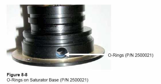
14 EECPC 3790 Removable Saturator II
15 EECPC Live-Time Processing Live-Time Electronics Processing: Real-time single particle counters use electronics to process particle detector pulses. In order to turn the raw counts from a single-particle counter into a concentration, the following formula must be used: C = N Q t C is the number concentration (particles per unit of volume) N is the number of pulses/particles counted in sample time t Q is the flow rate through the sensing instrument t is the sampling time
16 EECPC Live-Time Processing For all single particle counting instruments there is a fraction of time during which the designed detector is occupied, and no other electronic signals can be processed. During this non-detecting time, additional particle events can not be captured, so this time is not technically part of the sampling time of the aerosol. In order to accurately represent the concentration of particles in the aerosol stream, the non-detecting time must be subtracted from the sample time, and the resulting live-time should be used in the concentration calculations.
17 EECPC Live-Time Processing The non-detecting time is composed of two components: t dead Dead Time: The dead time is the time until another particle can trigger the detector. This can be measured using a high speed clock and accumulator. τ Dead Time Factor: Since the electronic pulses are not perfect square waves, there is an additional portion of time when the electronics are not available due to overlapping tails of adjacent particle signals. This time is dependent on the specific pulse output and detection scheme of the particle counter, and is therefore instrument specific. A dead time factor is used to quantify this effect.
18 EECPC Live-Time Processing Therefore, in order to achieve the highest concentration accuracy possible, the live time must be used in concentration calculations, and the nondetecting time must include the dead time of the electronics (t dead ) and a dead time factor (t ) dependent on the pulse output. t live = t sample - (t dead x τ ) t live electronic live-time t sample sample time T dead electronic dead-time ; measured every Dt = 0.1 s in the 3790 τ dead time factor, experimentally determined for 3790 (t = 1.9) C D = N V t t live = N Q t t t live = N Q t live
19 EECPC Live-Time Processing C D N = V t t live N t = Q t t live N = Q t live
20 EECPC Live-Time Processing Live-time electronics processing compensates for the finite time needed for signal processing It increases the accuracy of the number concentration measurement. When using live-time electronics processing, number concentration is always higher than the concentration calculated using the standard sample time.
21 EECPC 3790 Counting Efficiency

22 EECPC 3790 Linearity Response
23 EECPC 3790 Response Time
24 Heavy-duty Diesel Vehicles PN emission limit values expected for EURO 6 (Regulation 49) Heavy-duty validation exercise begins this month Led by Chris Parkins, UK Dept. for Transport 2-year program similar to light-duty, interlaboratory correlation exercise 7 EU labs JRC (first and last sight) UTAC (France) AVL-MTS (Sweden) EMPA (Switzerland) 2 more labs yet to be confirmed 4 non-eu labs NTSEL (Japan) Environment Canada NIER (Korea) JARI (Japan) Engine manufacturers planning round-robin exercise as well
25 Update from Milan Particle number (PN) emission limit value announced by European Commission for EURO 5 Regulation 83 (appendix 5) Applies to emissions from light-duty vehicles only M 1 and N 1 category vehicles 5 x particles/km Proposed effect date: 2009 The EECPC is for EURO 5 Regulation 83 compliance.
26 Summary EECPC3790 Improvements over 3010D Anti-spill/flooding design Condensate removal to prevent performance issues due to absorption of water in butanol Separate saturator and condenser temperature controls to prevent shifting of lower detection limit Removable saturator for ease of maintenance Modern interfaces (i.e. USB, Ethernet) Built-in data logging capabilities Meets PMP guidelines. (Regulations 49 and 83)