LOW IMPACT DEVELOPMENT BIO-SORPTION ACTIVATED MEDIA
|
|
|
- Meghan McGee
- 5 years ago
- Views:
Transcription
1 LOW IMPACT DEVELOPMENT BIO-SORPTION ACTIVATED MEDIA M A R T Y W A N I E L I S T A S T O R M W A T E R M A N A G E M E N T A C A D E M Y J U L Y, O R L A N D O F L O R I D A W W W. S T O R M W A T E R. U C F. E D U Florida Environmental Network, Inc
?")

2 PURPOSE OF PRESENTATION IS TO: What are Low Impact Development LID Characteristics? Why use Bio-sorption Activated Media (BAM)? Present Case Studies where BAM is being used by local government. Computation aids to assist in implementing LID BAM BMPTRAINS Available from: and for legacy programs
3 LOW IMPACT DEVELOPMENT CHARACTERISTICS Take no more land: Fit into existing development plans. Examples: depression areas, landscape areas, underground vaults, greenroofs, pervious pave, and Flood Control areas. Can replicate runoff conditions of existing land uses. Reduces runoff pollution and thus helps meet TMDL and BMAPs Offer aesthetic improvements. And to a lesser extent, Promote more green infrastructure. OBJECTIVE: To show how BAM fits into plans to take no more area, help replicate runoff conditions, improve aesthetics and reduce pollution into our waters. Taking no more land is important to local governments interest in maximizing tax revenue while meeting water quality constraints.
4 WHY USE BIO-SORPTION MEDIA BEING USED MORE FREQUENTLY ESPECIALLY IN URBAN AREAS Used to meet Post=Pre Nutrient Loadings. Detention or flow through devices Combinations of LIDs such as greenroofs, under-ground vaults, and reuse of stormwater. All can use bio-sorption media. Help meet BMAP allocations. Wet detention ponds discharges Swales and exfiltration. Help remove both N & P species before entering groundwater. Using landscaping with tree wells and rain gardens to reduce N&P species. Pervious pavement with BAM Regional retention basins with bottom added BAM.


5 PERVIOUS PAVEMENT LID OPTION RETENTION BASIN WET DETENTION EXFILTRATION TRENCH RAIN (BIO) GARDEN Unit Individual Level SWALE USER DEFINED BMP PERVIOUS PAVEMENT GREENROOF STORMWATER HARVESTING RAINWATER HARVESTING FILTRATION including Up-Flow Filters FLOATING ISLANDS WITH WET DETENTION LINED REUSE POND & UNDERDRAIN INPUT NOTE!!!: All individual system must be sized prior to being analyzed in conjunction with other systems. Please read instructions in the CATCHMENT AND TREATMENT SUMMARY RESULTS tab for more information. VEGETATED NATURAL BUFFER VEGETATED FILTER STRIP VEGETATED AREA Example tree well CATCHMENT AND TREATMENT SUMMARY RESULTS BAM under the pavement
")


6 GREENROOFS (ONE NEAR SARASOTA) BAM Mondo, Muhly, Coontie, And specimen plants In a bed of rounded rock Over B&G media John Wheeler Landscaping


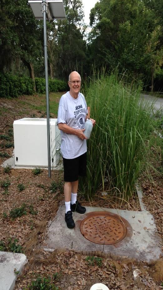
7 UNDERGROUND SYSTEMS IN HIGH WATER TABLE AREAS UP-FLOW FILTER AT THE DISCHARGE BAM

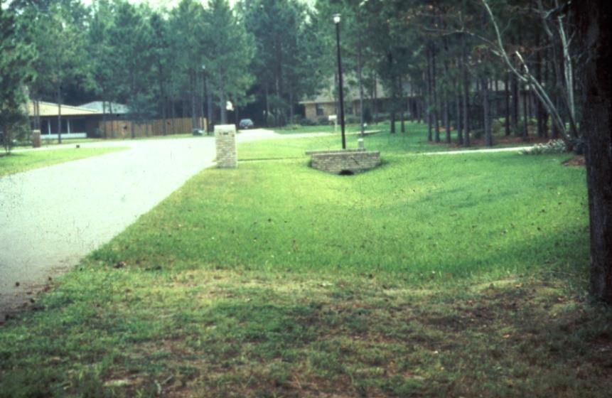
8 ON-SITE RETENTION LIDS EXFILTRATION, SWALES,


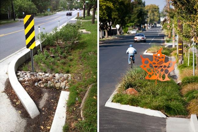
9 Tree Well and Interceptor Design Overflow storage tree anchors Overflow if not diverted BAM Overflow Flow to Tree Well Flow to Tree Wells Overflow


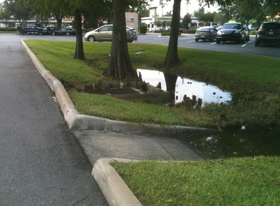
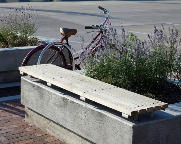
10 Street and Parking Lot Rain Gardens


11 COMBINING LID METHODS (COMMUNITY LEVEL) Retrofit Opportunities


12 UNDER GROUND TREATMENT WITH BAM IF NO BAM IN THE GROUND, USE B&G On-Site Under Ground Treatment BAM B&G at the on Bottom bottom Diffuse TN/TP source Regional Treatment Flow direction Contaminant groundwater plume Treatment zone known as Gate Low permeable zone known as 'Funnel'


13 UNDER GROUND TREATMENT WITH BAM Flow Through BAM with Plants BAM
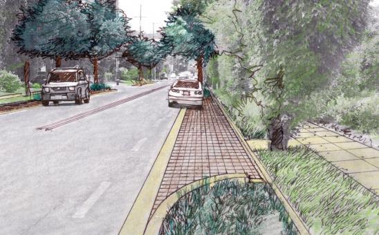


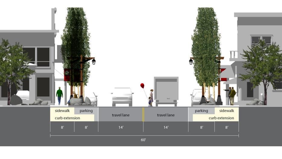
14 PERVIOUS PAVEMENTS, SWALES, AND RAIN GARDENS ABOVE GROUND LID OPTIONS
15 THE QUESTIONS OF MEETING LOADING REDUCTIONS Can one BMP meet loading reduction target? Not always. Wet ponds do not achieve 80% reduction of N, or must occupy large areas to meet only the P reduction (about 200 days residence time). To Remove more, use a treatment train Swales before the wet pond. Convert a wet pond to a reuse pond (stormwater harvesting). There may not be sufficient area for a swale or need for reuse water. Thus use an up-flow filter within a drainage pipe that you can provide storage and use a sorption media and in a treatment train.
16 WET DETENTION SYSTEMS MAY NEED TO REMOVE MORE N&P SPECIES


17 TYPICAL FAILURE PROBLEMS ASSOCIATED WITH SIDE BANK FILTERS Some Failure Problems Filters are difficult to access to properly clean Because of slow filtration or no filtration, exotics take over Often difficult or very costly to replace
18 WATERMARK ENGINEERING GROUP, INC. Example Pond Retrofit Design for Upflow Filter THE NEW UP-FLOW FILTER REPLACES AN OLD UN-SERVICEABLE SIDE BANK SYSTEM
19 DESIGN by Watermark Engineering Group THE UP-FLOW FILTER DESIGN ALLOWS FOR EASY INSPECTION AND SERVICE OF THE MEDIA


20 UP-FLOW FILTER INSTALLATION BY SUNTREE TECHNOLOGIES


21 IMPROVED TREATMENT USING AN UP- FLOW FILTER WITH WET POND Observations Filters can be designed to remove nitrogen without media replacement For phosphorus, media replacement time is specified Can be easily cleaned Can be used in BMP Treatment Train
 1.83 0.73 42.")
22 UP-FLOW WITH WET DETENTION PERFORMANCE DATA Summary Data Concentration data based Averages based on 6 events Construction cost less than under drains Average yearly based 1.0 inch design for filter Permanent pool MEDIA ROCK Parameter TN TP TSS Average Influent Concentration (mg/l) Average Filter Removal (%) Average Pond Removal (%) Average Pond + Filter Removal (%) Average Annual System Performance
23 FIELD DATA FIELD DATA ph Turbidity DO Temp Date: Pond In Filter In Filter Out Pond In Filter In Filter Out Pond In Filter In Filter Out SU SU SU NTU NTU NTU mg/l mg/l mg/l o C 3/ / / / / AVG % Change based on pond influent 86% 89% 7% 89% % Change due to filter 18% 88% USING 5 SAMPLES: NOx (mg/l) IN=0.77 OUT= % removal
24 DESIGN CHART ASSISTANCE Insi de Di m Fi l ter Area Release (CF) Release (CF) Total volume ftxft (SF) Max CFS 1st Day* next 2 days 3 days (CF) 4 x x x x x x x x x note: rate of maximum filtration is CFS/SF * half the maximum Note: Example Calculations for a 14 SF filter. filter area < vault area Column 3: Max CFS = 1 GPM/SF x CFS/GPM x 14 SF = CFS Column 4: Release in 1 st day = CFS x 86,400 sec/day / 2 = 1347 CF Column 5: Remaining half is released, thus 1347, extended value is Column 6: Sum of water released in 3 days (round off values)

25 OFF-LINE ULTRA URBAN FILTER BLUE COVE LAKE- FDOT DISTRICT 5

 Off-line Filter SECTIO N")
26 BLUE COVE LAKE FDOT DISTRICT 5 Reference: FDOT Project BDK , May 2014 Demonstration: Bio Media for Ultra Urban Stormwater Treatment Diversion Box (Smart) Off-line Filter SECTIO N

 0.502 0.")
27 SAMPLING RESULTS AND INSTALLATION PHOTOS 70% OF FLOW THROUGH FILTER (PHOTO CREDIT: FDOT OCALA) Inlet Outlet Temporary Covers Prevent Media Loss TM BOLD & GOLD Average Concentration and % Removal TN TP TSS Concentration from the Street (mg/l) Concentration to the Filter (mg/l) Concentration from the Filter (mg/l) Average Filter Removal (%) Overall Average Removal (%) Annual Average Removal (%)


28 0.7 ac basin, 10 ft deep, 51 bottom ~61-62 at the top GROUNDWATER PROTECTION, 56 ac drainage basin, only 4.2 ac EIA Water table ~10 ft below basin bottom MARION CO BASIN Well sampling locations Well Locations N 30-in CMP 42-in CMP 42-in CMP

29 Flood Control Basin OPERATING PHOTO AFTER PLACEMENT OF EROSION CONTROL BLANKET ON BERM AND 3.7 INCH STORM Nutrient or Pollution Control Basin

30 Nitrate Present in This volume of soil Before amendment Verification phase
31 AFTER BAM NITRATE 50-80% reductions in nitrate from pre-construction ( ) to post-construction ( ) median concentrations in soil water and at the water table. Stormwater Soil Water Groundwater Nitrate decreases most likely due to dilution, sorption, reduced nitrification, denitrification, anammox, or some combination of these processes. Preconstruction Postconstruction
32 AFTER BAM PHOSPHORUS 70 90% reductions in total dissolved phosphorus (TDP) from pre-construction ( ) to post-construction ( ) median concentrations in soil water No change in TDP at water table. TDP decreases may be due to dilution, sorption, precipitation, microbial assimilation, or some combination of these processes ortho-p > 80% TDP, total P (unfiltered) is ~1 10x TDP Soil Water Preconstruction Stormwater Postconstruction Groundwater
![COMPUTATIONAL AIDS: BMPTRAINS MODEL AND SMADA PROGRAMS Stormwater BMP Treatment Trains [BMPTRAINS ] CLICK HERE TO START INTRODUCTION PAGE Model requires the use of Excel 2007 or newer 1) There is a](/docs-images/89/101001485/images/33-1.jpg "users manual to help navigate this program and it is available at www.stormwater.ucf.")

33 COMPUTATIONAL AIDS: BMPTRAINS MODEL AND SMADA PROGRAMS Stormwater BMP Treatment Trains [BMPTRAINS ] CLICK HERE TO START INTRODUCTION PAGE Model requires the use of Excel 2007 or newer 1) There is a users manual to help navigate this program and it is available at This program is compiled from stormwater management publications and deliberations during a two year review of the stormwater rule in the State of Florida. Input from the members of the Florida Department of Environmental Protection Stormwater Review Technical Advisory Committee and the staff and consultants from the State Water Management Districts is appreciated. The State Department of Transportation provided guidance and resources to compile this program. The Stormwater Management Academy is responsible for the content of this program. 2) This spreadsheet is best viewed at 1280 BY 1080 PIXELS screen resolution. If the maximum resolution of your computer screen is lower than 1280 BY 1080 PIXELS you can adjust the view in the Excel VIEW menu by zooming out to value smaller than 100 PERCENT. 3) This spreadsheet has incorporated ERROR MESSAGE WINDOWS. Your analysis is not valid unless ALL ERROR MESSAGE WINDOWS are clear. 4) PRINTING INSTRUCTIONS: Print the page to MICROSOFT OFFICE DOCUMENT IMAGE WRITER (typically the default) or ADOBE PDF, save the page as an image document, then print the document you saved. 5) Click on the button located on the top of this window titled CLICK HERE TO START to begin the analysis. Disclaimer: These workbooks were created to assist in the analysis of Best Management Practice calculations. All users are responsible for validating the accuracy of the internal calculations. If improvements are noted within this model, please Marty Wanielista, Ph.D., P.E. at martin.wanielista@ucf.edu with specific information so that revisions can be made. BMPTRAINS Available from: and for legacy programs The authors of this program were Christopher Kuzlo, Marty Wanielista, Mike Hardin, and Ikiensinma Gogo-Abite. This is version 7.3 of the program, updated on June 20, Comments are appreciated.


34 Conclusions 1. Many examples of LIDs with BAM for new- and re-development. 2. BAM is being used to help meet BMAP allocations, post=pre loadings and to protect groundwater. 3. There is credit being given by regulatory agency personnel. 4. BMPTRAINS can be used to assign effectiveness. Seal of Approval
35 QUESTIONS, REMARKS AND DISCUSSION M A R TY WA N I E LI S TA July, 2016 Orlando Florida