GEOTECHNICAL SUBSURFACE DATA REPORT
|
|
|
- Oswin Lindsey
- 5 years ago
- Views:
Transcription
1 GEOTECHNICAL SUBSURFACE DATA REPORT SC-41 REPLACEMENT BRIDGE OVER MAIDEN DOWN SWAMP MARION COUNTY, SOUTH CAROLINA PREPARED FOR Mr. Joshua Meetze, E.I.T. RPG-2 GDS South Carolina Department of Transportation 955 Park Street Columbia, South Carolina PREPARED BY F&ME Consultants, Inc Devine Street Columbia, South Carolina OCTOBER 1, 2015 SCDOT Project ID. P F&ME Project No. G
2
3 TABLE OF CONTENTS I. INTRODUCTION... 3 A. General... 3 B. Scope... 3 II. FIELD INVESTIGATION SUMMARY... 3 A. Soil Test Borings (STB)... 4 B. Electro-Piezocone Soundings (CPT)... 4 C. Downhole Seismic Tests (SW)... 5 D. Bulk Sample (BS)... 5 E. Groundwater... 6 III. SOIL LABORATORY TESTING... 7 A. LOCATION PLANS Figure 1: Site Location Plan Figure 2: Boring Location Plan B. SUBSURFACE EXPLORATION Soil Test Boring Logs (STB) Electro-Piezocone Soundings (CPT) C. LABORATORY TESTING Section 1: Split-Spoon Samples Section 2: Bulk Sample APPENDIX D. DOWNHOLE SHEAR WAVE VELOCITY TESTING SW-1 E. REQUEST FOR WORK Request for Preliminary Subsurface Exploration and Laboratory Testing Soil Laboratory Testing F. SPT HAMMER CALIBRATION Drill Rig SPT Hammer Energy Calibration Report G Geotechnical Subsurface Data Report for SC-41 Replacement Bridge over Maiden Down Swamp Page 2 of 7
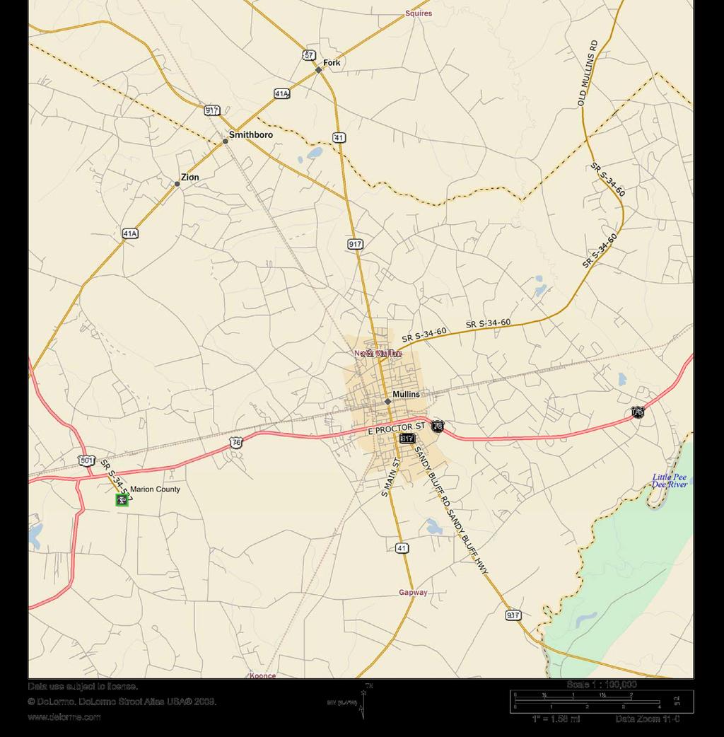
4 I. INTRODUCTION A. General The SC-41 Replacement Bridge over Maiden Down Swamp is located in Marion County, South Carolina. We understand that the primary objective for the project is to replace the existing bridge on alignment. The total length for the new bridge structure is approximately 0 feet with additional roadway improvements. A Site Location Plan is presented as Figure 1 in Appendix A of this report. B. Scope F&ME performed a geotechnical subsurface investigation and laboratory testing for the bridge and roadway portion of the SC-41 Replacement Bridge over Maiden Down Swamp. The South Carolina Department of Transportation (SCDOT) request and scope for the geotechnical subsurface investigation was issued on June 8, 2015, and a subsequent laboratory testing scope was issued on August 21, Copies of these requests can be found in Appendix E. The field investigation included soil test borings (STB), electro-piezocone soundings (CPT), shear wave velocity measurements using downhole methods (SW), and obtaining a bulk sample (BS). Laboratory testing was performed on soil samples collected from the test borings and bulk soil sample. All exploration methods and laboratory procedures were conducted in accordance with the most recent American Association of State Highway and Transportation Officials (AASHTO), American Society of Testing and Materials (ASTM) Standards, and the SCDOT Geotechnical Design Manual (GDM). This report was prepared in general accordance with the 20 SCDOT Geotechnical Design Manual (GDM), Version 1.1. II. FIELD INVESTIGATION SUMMARY From August 11 through 19, 2015, F&ME performed five (5) soil test borings (STB), two (2) electro-piezocone soundings (CPT), one (1) downhole seismic test (SW), and obtained one (1) bulk sample (BS) at locations along the length of the proposed roadway improvements and bridge replacement. MicroStation files with the roadway plans and stationing, as well as test boring locations and test hole number designations, were provided by the SCDOT. The soil test borings were advanced using a CME 550 ATV mounted drill rig with an automatic standard penetration test (SPT) hammer system. Soil test borings were advanced to the individual target depths provided by the SCDOT. Rotary wash drilling techniques were used to maintain a stable borehole. Borings were advanced with standard split-spoon sampling to the boring termination depths requested by the SCDOT or to auger refusal. Details of each boring are included on the individual Soil Test Boring Logs in Appendix B. G Geotechnical Subsurface Data Report for SC-41 Replacement Bridge over Maiden Down Swamp Page 3 of 7
5 A. Soil Test Borings (STB) The following table is a summary of the soil test boring designations, depths, locations, and surface elevations. Test Hole No. Soil Depth (ft.) Surface Condition Total Air Gap Depth (ft.) SOIL TEST BORINGS (STB) Total Boring Depth (ft.) Station Offset Distance (ft.) Latitude Longitude TOB Elev. (ft.-msl) B-1 20 Asphalt Roadway N/A RT B-2 80 Asphalt Roadway N/A RT B-3 0 Concrete Bridge Deck RT B Grass Shoulder N/A RT B-5 20 Asphalt Roadway N/A RT Totals B. Electro-Piezocone Soundings (CPT) The following table is a summary of the electro-piezocone sounding designations, depths, locations, and surface elevations. CPT testing was performed on the bridge approach embankments at each end of the bridge. CPT-1 and CPT-2 were both terminated due to refusal. CPT locations are shown on Figure 2 in Appendix A. Detailed descriptions of each CPT are shown in Appendix B of this report. A CD with an electronic copy of the spreadsheet meeting SCDOT requirements for CPT will be delivered with the report. Test Hole No. Soil Depth (ft.) CPT CPT Totals 60.9 ELECTRO-PIEZOCONE SOUNDINGS (CPT) Surface Condition Station Offset Distance TOB Elev. Latitude Longitude (ft.) (ft.-msl) Grass Shoulder RT Grass Shoulder RT G Geotechnical Subsurface Data Report for SC-41 Replacement Bridge over Maiden Down Swamp Page 4 of 7
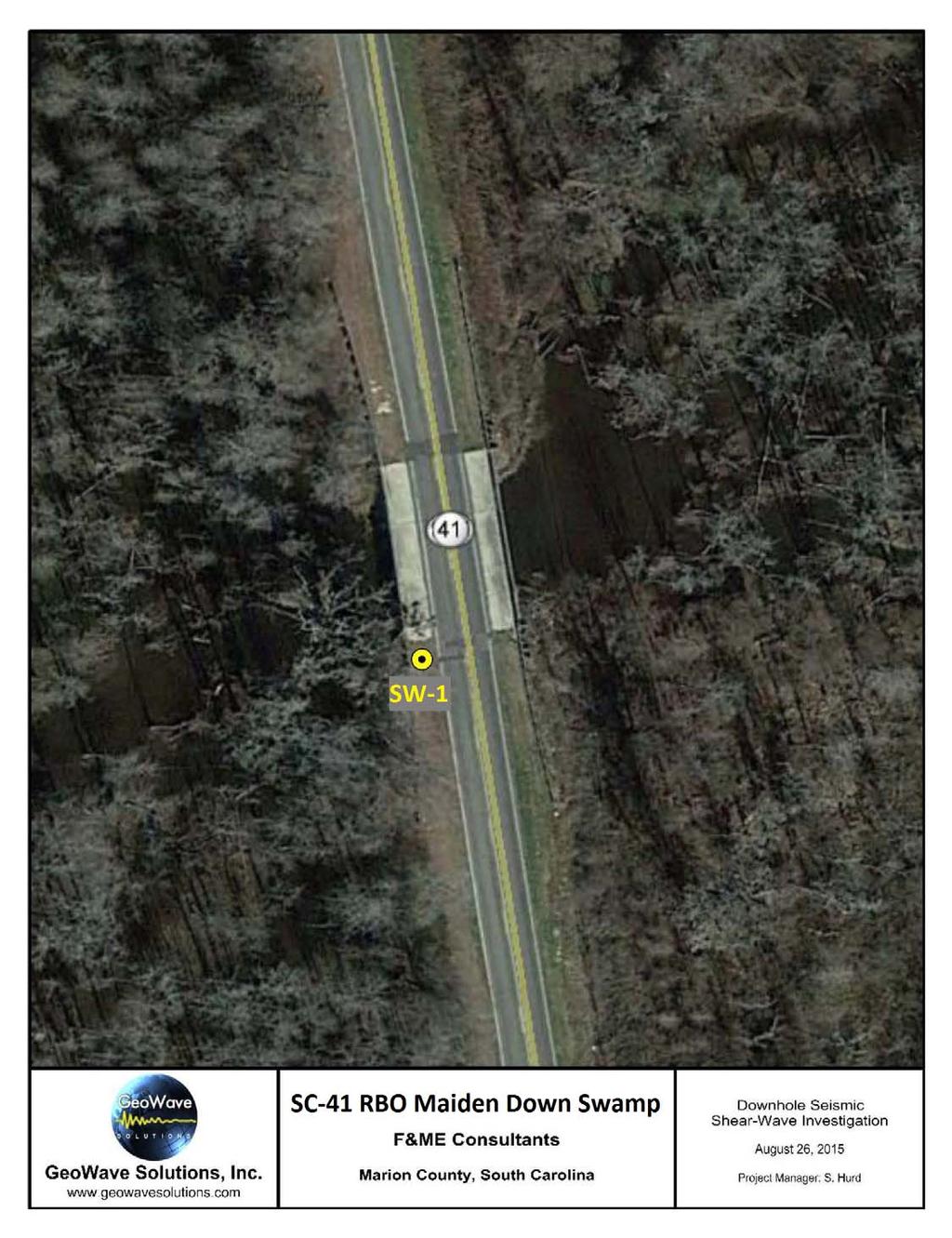
6 C. Downhole Seismic Tests (SW) The following table is a summary of the downhole seismic test designation, depth, location, and surface elevation. One (1) downhole seismic shear-wave test was performed in soil test boring B-4. The downhole seismic test was designated as SW- 1. Soil test boring B-4 was drilled to a depth of one hundred and twenty (120) feet below the existing ground surface. Two (2) inch PVC casing was installed in the boring to a depth of one hundred and seventeen (117) feet below the existing ground surface. Prior to performing the downhole seismic test for SW-1, the location needed to be dewatered in order to obtain accurate results. A report outlining the test methodology and results of the downhole seismic shear wave investigation are included in Appendix D of this report. Test Hole No. Soil Test Boring I.D. Soil Depth (ft.) Casing Depth (ft.) DOWNHOLE SEISMIC TESTS (SW) Station Offset Distance (ft.) Latitude Longitude TOB Elev. (ft.-msl) SW-1 B RT Totals D. Bulk Sample (BS) F&ME was requested to obtain one (1) bulk sample from the auger cuttings within the upper 5 feet from soil test boring B-2. SCDOT required rotary wash drilling to be performed for the soil test borings. Auger cuttings were not available due to rotary wash drilling techniques. F&ME performed an offset boring approximately five (5) feet from soil test boring B-2 within the existing bridge approach embankment. A manual auger boring was performed in order to obtain the bulk soil sample. The bulk sample location and depth was selected by the SCDOT. Bulk Sample BS-1 (Offset from B-2) Surface Condition Grass Shoulder Sample Depth (ft.) BULK SAMPLE (BS) Offset Station Distance (ft.) Latitude Longitude Elev. (ft.-msl) RT G Geotechnical Subsurface Data Report for SC-41 Replacement Bridge over Maiden Down Swamp Page 5 of 7
7 E. Groundwater Groundwater depth measurements were made at the time of boring for all borings, and are noted on the individual Soil Test Boring Logs in Appendix B. Groundwater measurements were also made twenty-four (24) hours following boring completion for soil test borings B-2, B-3, and B-4. Soil test borings B-1 and B-5 were backfilled following completion of drilling due to the borings being located within the existing roadway. Twenty-four (24) hour groundwater tables were not recorded in soil test borings B-1, and B-5. The following table is a summary of the groundwater measurements for the soil test borings at time of boring (TOB) and twenty-four (24) hours following boring completion. Groundwater measurements for electro-piezocone soundings were interpreted from the cone penetration testing logs. Boring No. Date of TOB Groundwater Measurement GROUNDWATER DEPTH TOB Groundwater Depth (ft.) 24-hr. Groundwater Depth (ft.) B Backfilled at Completion of Drilling B B B B Backfilled at Completion of Drilling CPT Backfilled at Completion of Drilling CPT Backfilled at Completion of Drilling G Geotechnical Subsurface Data Report for SC-41 Replacement Bridge over Maiden Down Swamp Page 6 of 7
8 III. SOIL LABORATORY TESTING Following completion of F&ME s field investigation, preliminary soil test boring logs were prepared and submitted to the SCDOT. Based on the data represented in these logs, soil samples were selected by the SCDOT for laboratory testing. The selected samples were tested in F&ME s laboratory to determine applicable physical and engineering properties. This included split-spoon samples and one (1) composite bulk sample. All laboratory testing was performed in accordance with procedures set forth in the most recently published AASHTO and ASTM standards. The laboratory testing performed for the split-spoon samples are detailed in the table below. Data sheets containing the results of the laboratory testing are provided in Appendix C, Section 1 of this report. LABORATORY SOIL TESTING (SPLIT-SPOON SAMPLES) Type of Test Quantity Procedure Wash # AASHTO T11 Grain Size w/ Wash #200 3 AASHTO T88 Atterberg Limits 21 AASHTO T89/T90 Moisture Content 28 ASTM D2216 Organic Content 3 AASHTO T267 ph 1 AASHTO T289 Chloride Content 1 AASHTO T291 Sulfate Content 1 AASHTO T290 Resistivity 1 AASHTO T288 On August 21, 2015, F&ME received the laboratory testing request from SCDOT for the bulk soil sample. The laboratory testing performed for the bulk sample is detailed in the table below and data sheets containing the results are provided in Appendix C, Section 2 of this report. LABORATORY SOIL TESTING (BULK SAMPLE) Type of Test Quantity Procedure Atterberg Limits 1 AASHTO T89/T90 Moisture Content 1 ASTM D2216 Grain Size Analysis with Hydrometer 1 AASHTO T88 Standard Proctor 1 AASHTO T99 CU Triaxial 1 AASHTO T236 G Geotechnical Subsurface Data Report for SC-41 Replacement Bridge over Maiden Down Swamp Page 7 of 7
9 APPENDIX A LOCATION PLANS G Geotechnical Subsurface Data Report for SC-41 Replacement Bridge over Maiden Down Swamp
10
11
12 APPENDIX B SUBSURFACE EXPLORATION G Geotechnical Subsurface Data Report for SC-41 Replacement Bridge over Maiden Down Swamp
13 Soil Test Log Project ID: P County: Marion Boring No.: B-1 Site Description: SC 41 Bridge Over Maiden Down Swamp Route: SC-41 Eng./Geo.: M. Touchberry Boring Location: Offset: 6' RT Alignment: On Elev.: 70.2 ft Latitude: Longitude: Date Started: 8/13/2015 Total Depth: 20 ft Soil Depth: 20 ft Core Depth: 0 ft Date Completed: 8/13/2015 Bore Hole Diameter (in): 4 Sampler Configuration Liner Required: Y N Liner Used: Y Drill Machine: CME 550 Drill Method: RW Hammer Type: Automatic Energy Ratio: 74% Core Size: N/A Driller: D. Harris Groundwater: TOB 13 ft 24HR NR N SPT N VALUE Elevation (ft) Depth (ft) 0.0 Roadway 0.3 ASHPALT (4") MATERIAL DESCRIPTION FILL Medium Dense, Dry to Moist, Light Olive Brown, None to Low Plasticity, Clayey Fine to Coarse SAND (SC), Munsell=2.5Y 5/6 Graphic Log Sample Depth (ft) Sample No./Type SS-1 1st 6" 2nd 6" 14 3rd 6" 12 N Value 26 PL MC LL FINES CONTENT (%) => Strong Brown, Munsell=7.5YR 5/8 SS th 6" = 8 Blows Loose to Medium Dense, Moist to Wet, Stong Brown, Medium Plasticity, Silty Fine to Coarse SAND (SM), Munsell=7.5YR 5/8 LL=37, PL=25, PI=12, NMC=18.8%, %#200= SS th 6" = 8 Blows SS th 6" = 6 Blows => Olive Gray, Fine to Medium Sand, Munsell=5Y 5/2.0 SS th 6" = 6 Blows SC_DOT G SC 41 RBO MAIDEN SWAMP.GPJ SCDOT DATA TEMPLATE_12_30_2014.GDT /1/ SS - UD - AWG ALLUVIUM Loose to Medium Dense, Moist, Very Dark Gray, Non-Plastic, Silty Fine to Coarse SAND (SM), with Trace of Organics, Munsell=5Y 3/1 LL=NP, PL=NP, PI=NP, NMC=41.5%, %#200=29.3 => Wet, Light Gray, Non-Plastic, with Wood Fragments, Munsell=5Y 7/1 NMC=32.2%, %#200=14.5, Organics=0.6% => with Gravel Split Spoon Undisturbed Sample Rock Core, 1-1/8" Boring Terminated at 20.0 feet SAMPLER TYPE NQ - Rock Core, 1-7/8" CU - Cuttings CT - Continuous Tube LEGEND HSA CFA DC SS-6 SS-7 SS-8 SS Hollow Stem Auger Continuous Flight Augers Driving Casing DRILLING METHOD RW - RC - 4th 6" = 5 Blows 4th 6" = 3 Blows 4th 6" = 12 Blows Rotary Wash Rock Core
14 Soil Test Log Project ID: P County: Marion Boring No.: B-2 Site Description: SC 41 Bridge Over Maiden Down Swamp Route: SC-41 Eng./Geo.: M. Touchberry Boring Location: Offset: 6' RT Alignment: On Elev.: 70.2 ft Latitude: Longitude: Date Started: 8/12/2015 Total Depth: 80 ft Soil Depth: 80 ft Core Depth: 0 ft Date Completed: 8/12/2015 Bore Hole Diameter (in): 4 Sampler Configuration Liner Required: Y N Liner Used: Y Drill Machine: CME 550 Drill Method: RW Hammer Type: Automatic Energy Ratio: 74% Core Size: N/A Driller: D. Harris Groundwater: TOB 13 ft 24HR ft N SPT N VALUE Elevation (ft) 65.2 Depth (ft) 0.0 Roadway MATERIAL DESCRIPTION ASPHALT (2") RECYCLED ASPHALT PAVEMENT (4") FILL Medium Dense to Loose, Moist, Yellowish Brown, Low Plasticity, Silty, Clayey Fine to Coarse SAND (SC-SM), Munsell=YR 5/6 => Yellowish Red, Munsell=5YR 5/8 => Strong Brown, Munsell=7.5YR 5/8 LL=26, PL=21, PI=5, NMC=13.0%, %#200=19.6 Graphic Log Sample Depth (ft) Sample No./Type SS-1 SS-2 SS-3 1st 6" nd 6" rd 6" N Value PL MC 4th 6" = 7 Blows 4th 6" = 5 Blows LL FINES CONTENT (%) SC_DOT G SC 41 RBO MAIDEN SWAMP.GPJ SCDOT DATA TEMPLATE_12_30_2014.GDT /1/ SS - UD - AWG Split Spoon Undisturbed Sample Rock Core, 1-1/8" Loose, Moist, Yellowish Brown, Medium Plasticity, Silty Fine SAND (SM), Munsell=YR 5/6 LL=38, PL=26, PI=12, NMC=21.7%, %#200=41.8 Firm, Moist to Wet, Light Olive Brown, Low Plasticity, Fine Sandy SILT (ML), Munsell=2.5Y 5/4 LL=36, PL=26, PI=, NMC=21.5%, %#200=52.6 Very Loose, Wet, Light Olive Brown, Non-Plastic, Silty Fine to Medium SAND (SM), Munsell=2.5Y 5/4 ALLUVIUM Very Loose, Wet, Black, Non-Plastic, Silty Fine to Medium SAND (SM), with Few Organics, Munsell=2.5Y 2.5/1 LL=NP, PL=NP, PI=NP, NMC=39.0%, %#200=41.0, Organics=7.2% Medium Dense, Wet, Very Dark Grayish Brown, None to Low Plasticity, Clayey Fine to Medium SAND (SC), Munsell= 2.5Y 3/2 Medium Dense, Wet, Gray, Non-Plastic, Silty Fine to Medium SAND (SM), Munsell=2.5Y 5/1 => Dark Grayish Brown, with Gravel, Munsell=2.5Y 4/2 SAMPLER TYPE NQ - Rock Core, 1-7/8" CU - Cuttings CT - Continuous Tube LEGEND HSA CFA DC SS-4 SS-5 SS-6 SS-7 SS-8 SS Hollow Stem Auger Continuous Flight Augers Driving Casing DRILLING METHOD RW - RC - 4th 6" = 2 Blows 4th 6" = 12 Blows 4th 6" = 4 Blows 4th 6" = 4 Blows 4th 6" = 2 Blows Continued Next Page Rotary Wash Rock Core
15 Soil Test Log Project ID: P County: Marion Boring No.: B-2 Site Description: SC 41 Bridge Over Maiden Down Swamp Route: SC-41 Eng./Geo.: M. Touchberry Boring Location: Offset: 6' RT Alignment: On Elev.: 70.2 ft Latitude: Longitude: Date Started: 8/12/2015 Total Depth: 80 ft Soil Depth: 80 ft Core Depth: 0 ft Date Completed: 8/12/2015 Bore Hole Diameter (in): 4 Sampler Configuration Liner Required: Y N Liner Used: Y Drill Machine: CME 550 Drill Method: RW Hammer Type: Automatic Energy Ratio: 74% Core Size: N/A Driller: D. Harris Groundwater: TOB 13 ft 24HR ft N SPT N VALUE Elevation (ft) Depth (ft) MATERIAL DESCRIPTION Medium Dense, Wet, Dark Grayish Brown, Non-Plastic, Silty Fine to Medium SAND (SM), Munsell=2.5Y 4/2 Graphic Log Sample Depth (ft) Sample No./Type 1st 6" 2nd 6" 3rd 6" N Value PL MC LL FINES CONTENT (%) => White, Munsell=2.5Y 8/1 NMC=64.9%, %#200= SS => Brownish Yellow, YR 6/ => Greenish Gray, with Gravel, Munsell=GLEY1 5/N Very Stiff, Wet, Greenish Black, Low Plasticity, CLAY (CL), with Fine Sand, Munsell=GLEY1 2.5/GY 28.5 SS SC_DOT G SC 41 RBO MAIDEN SWAMP.GPJ SCDOT DATA TEMPLATE_12_30_2014.GDT /1/ SS - UD - AWG Split Spoon Undisturbed Sample Rock Core, 1-1/8" Medium Dense to Dense, Moist to Wet, Gray, Non-Plastic, Fine to Medium SAND (SP-SM), with Silt, Munsell=GLEY1 5/N LL=NP, PL=NP, PI=NP, NMC=26.3%, %#200=.9 SAMPLER TYPE NQ - Rock Core, 1-7/8" CU - Cuttings CT - Continuous Tube LEGEND HSA CFA DC SS-12 SS Hollow Stem Auger Continuous Flight Augers Driving Casing DRILLING METHOD RW - RC - Continued Next Page Rotary Wash Rock Core
16 Soil Test Log Project ID: P County: Marion Boring No.: B-2 Site Description: SC 41 Bridge Over Maiden Down Swamp Route: SC-41 Eng./Geo.: M. Touchberry Boring Location: Offset: 6' RT Alignment: On Elev.: 70.2 ft Latitude: Longitude: Date Started: 8/12/2015 Total Depth: 80 ft Soil Depth: 80 ft Core Depth: 0 ft Date Completed: 8/12/2015 Bore Hole Diameter (in): 4 Sampler Configuration Liner Required: Y N Liner Used: Y Drill Machine: CME 550 Drill Method: RW Hammer Type: Automatic Energy Ratio: 74% Core Size: N/A Driller: D. Harris Groundwater: TOB 13 ft 24HR ft N SPT N VALUE Elevation (ft) 25.2 Depth (ft) 44.5 MATERIAL DESCRIPTION Dense, Moist to Wet, Gray, Non-Plastic, Fine to Medium SAND (SP-SM), with Silt, Munsell=GLEY1 5/N => Brownish Yellow, Munsell=YR 6/8 Hard, Moist to Wet, Greenish Black, Low Plasticity, CLAY (CL), Munsell=GLEY1 2.5/5GY Graphic Log Sample Depth (ft) 43.5 Sample No./Type SS-14 1st 6" 9 2nd 6" 18 3rd 6" 24 N Value 42 PL MC LL FINES CONTENT (%) Dense, Wet, Gray, Non-Plastic, Fine to Medium SAND (SP), Munsell=GLEY1 5/N 48.5 SS SC_DOT G SC 41 RBO MAIDEN SWAMP.GPJ SCDOT DATA TEMPLATE_12_30_2014.GDT /1/ SS - UD - AWG Split Spoon Undisturbed Sample Rock Core, 1-1/8" Hard, Wet, Greenish Black, Low Plasticity, CLAY (CL), with Fine Sand, Munsell=GLEY1 2.5/Y Medium Dense, Wet, Greenish Gray, None to Low Plasticity, Clayey Fine to Coarse SAND (SC), with Wood Fragments Very Stiff, Wet, Greenish Black, Very Plastic, Elastic SILT (MH), with Fine Sand, Munsell=GLEY1 2.5/Y SAMPLER TYPE NQ - Rock Core, 1-7/8" CU - Cuttings CT - Continuous Tube LEGEND HSA CFA DC SS-16 SS Hollow Stem Auger Continuous Flight Augers Driving Casing DRILLING METHOD RW - RC - Continued Next Page Rotary Wash Rock Core
17 Soil Test Log Project ID: P County: Marion Boring No.: B-2 Site Description: SC 41 Bridge Over Maiden Down Swamp Route: SC-41 Eng./Geo.: M. Touchberry Boring Location: Offset: 6' RT Alignment: On Elev.: 70.2 ft Latitude: Longitude: Date Started: 8/12/2015 Total Depth: 80 ft Soil Depth: 80 ft Core Depth: 0 ft Date Completed: 8/12/2015 Bore Hole Diameter (in): 4 Sampler Configuration Liner Required: Y N Liner Used: Y Drill Machine: CME 550 Drill Method: RW Hammer Type: Automatic Energy Ratio: 74% Core Size: N/A Driller: D. Harris Groundwater: TOB 13 ft 24HR ft N SPT N VALUE Elevation (ft) 5.2 Depth (ft) MATERIAL DESCRIPTION Hard, Wet, Greenish Black, Very Plastic, Elastic SILT (MH), with Fine Sand, Munsell=GLEY1 2.5/Y LL=6, PL=48, PI=58, NMC=57.4%, %#200=74.6 Graphic Log Sample Depth (ft) 63.5 Sample No./Type SS-18 1st 6" 15 2nd 6" 25 3rd 6" 21 N Value 46 PL MC LL FINES CONTENT (%) SS /3" SC_DOT G SC 41 RBO MAIDEN SWAMP.GPJ SCDOT DATA TEMPLATE_12_30_2014.GDT /1/ SS - UD - AWG Split Spoon Undisturbed Sample Rock Core, 1-1/8" Boring Terminated at 80.0 feet SAMPLER TYPE NQ - Rock Core, 1-7/8" CU - Cuttings CT - Continuous Tube LEGEND HSA CFA DC SS-20 SS Hollow Stem Auger Continuous Flight Augers Driving Casing DRILLING METHOD RW - RC - Rotary Wash Rock Core
18 Soil Test Log Project ID: P County: Marion Boring No.: B-3 Site Description: SC 41 Bridge Over Maiden Down Swamp Route: SC-41 Eng./Geo.: M. Touchberry Boring Location: Offset: 6'RT Alignment: On Elev.: 70.1 ft Latitude: Longitude: Date Started: 8/11/2015 Total Depth: 117 ft Soil Depth: 0 ft Core Depth: 0 ft Date Completed: 8/11/2015 Bore Hole Diameter (in): 4 Sampler Configuration Liner Required: Y N Liner Used: Y Drill Machine: CME 550 Drill Method: RW Hammer Type: Automatic Energy Ratio: 74% Core Size: N/A Driller: D. Harris Groundwater: TOB 11.9 ft 24HR 11.9 ft SPT N VALUE N Elevation (ft) Depth (ft) MATERIAL DESCRIPTION 0.0 Bridge Deck 1.0 ASPHALT/CONCRETE (1.0') AIR GAP (17.0') Graphic Log Sample Depth (ft) Sample No./Type 1st 6" 2nd 6" 3rd 6" N Value PL MC LL FINES CONTENT (%) Top of Water SC_DOT G SC 41 RBO MAIDEN SWAMP.GPJ SCDOT DATA TEMPLATE_12_30_2014.GDT /1/ SS - UD - AWG Split Spoon Undisturbed Sample Rock Core, 1-1/8" Very Loose, Wet, Very Dark Gray, Medium Plasticity, Silty Fine to Coarse SAND (SM), with Organics, Munsell=YR 3/1 NMC=21.4%, %#200=12.7 NMC=22.5%, %#200=13.6 => Medium Dense to Dense, Moist to Wet, Light Greenish Gray, Munsell=GLEY1 7/Y NMC=26.2%, %#200=21.2 => Olive Yellow, Munsell=2.5Y 6/8 => Bluish Gray, Munsell=GLEY2 5/5PB => Bluish Black, Munsell=GLEY2 2.5/BG LL=50, PL=35, PI=15, NMC=46.9%, %#200=49.3 Dense, Moist to Wet, Olive Yellow, Non-Plastic, Fine to Medium SAND (SP), Munsell=2.5Y 6/8 SAMPLER TYPE NQ - Rock Core, 1-7/8" CU - Cuttings CT - Continuous Tube LEGEND HSA CFA DC SS-1 SS-2 SS-3 SS-4 SS-5 SS-6 SS-7 SS Hollow Stem Auger Continuous Flight Augers Driving Casing 4th 6" = 1 Blow 4th 6" = 42 Blows DRILLING METHOD RW - RC - 4th 6" = 8 Blows 4th 6" = 19 Blows 4th 6" = 19 Blows Continued Next Page Rotary Wash Rock Core
19 Soil Test Log Project ID: P County: Marion Boring No.: B-3 Site Description: SC 41 Bridge Over Maiden Down Swamp Route: SC-41 Eng./Geo.: M. Touchberry Boring Location: Offset: 6'RT Alignment: On Elev.: 70.1 ft Latitude: Longitude: Date Started: 8/11/2015 Total Depth: 117 ft Soil Depth: 0 ft Core Depth: 0 ft Date Completed: 8/11/2015 Bore Hole Diameter (in): 4 Sampler Configuration Liner Required: Y N Liner Used: Y Drill Machine: CME 550 Drill Method: RW Hammer Type: Automatic Energy Ratio: 74% Core Size: N/A Driller: D. Harris Groundwater: TOB 11.9 ft 24HR 11.9 ft SPT N VALUE N Elevation (ft) 25.1 Depth (ft) 45.5 MATERIAL DESCRIPTION Dense, Moist to Wet, Olive Yellow, Non-Plastic, Fine to Medium SAND (SP), Munsell=2.5Y 6/8 Dense to Medium Dense, Wet, Olive Yellow, Very Plastic, Silty Fine to Medium SAND (SM), Munsell=2.5Y 6/8 Graphic Log Sample Depth (ft) 45.5 Sample No./Type SS-9 1st 6" 17 2nd 6" 18 3rd 6" 25 N Value 43 PL MC LL FINES CONTENT (%) NMC=41.5%, %#200= SS => Dark Greenish Gray, Munsell=GLEY1 4/N 55.5 SS SC_DOT G SC 41 RBO MAIDEN SWAMP.GPJ SCDOT DATA TEMPLATE_12_30_2014.GDT /1/ SS - UD - AWG Split Spoon Undisturbed Sample Rock Core, 1-1/8" => Moist, Greenish Black, Munsell=GLEY1 2.5/Y LL=1, PL=59, PI=42, NMC=24.1%, %#200=12.4 Hard, Moist, Greenish Black, Low Plasticity, Fine Sandy CLAY (CL), Munsell=GLEY1 2.5/Y SAMPLER TYPE NQ - Rock Core, 1-7/8" CU - Cuttings CT - Continuous Tube LEGEND HSA CFA DC SS-12 SS-13 SS-14 SS-15 SS /4.5" Hollow Stem Auger Continuous Flight Augers Driving Casing DRILLING METHOD RW - RC - Continued Next Page Rotary Wash Rock Core >> 1
20 Soil Test Log Project ID: P County: Marion Boring No.: B-3 Site Description: SC 41 Bridge Over Maiden Down Swamp Route: SC-41 Eng./Geo.: M. Touchberry Boring Location: Offset: 6'RT Alignment: On Elev.: 70.1 ft Latitude: Longitude: Date Started: 8/11/2015 Total Depth: 117 ft Soil Depth: 0 ft Core Depth: 0 ft Date Completed: 8/11/2015 Bore Hole Diameter (in): 4 Sampler Configuration Liner Required: Y N Liner Used: Y Drill Machine: CME 550 Drill Method: RW Hammer Type: Automatic Energy Ratio: 74% Core Size: N/A Driller: D. Harris Groundwater: TOB 11.9 ft 24HR 11.9 ft SPT N VALUE N Elevation (ft) Depth (ft) MATERIAL DESCRIPTION Hard, Moist, Greenish Black, Low Plasticity, Fine Sandy CLAY (CL), Munsell=GLEY1 2.5/Y Graphic Log Sample Depth (ft) 85.5 Sample No./Type SS-17 1st 6" 13 2nd 6" 20 3rd 6" 28 N Value 48 PL MC LL FINES CONTENT (%) SS SS SS SC_DOT G SC 41 RBO MAIDEN SWAMP.GPJ SCDOT DATA TEMPLATE_12_30_2014.GDT /1/ SS - UD - AWG Split Spoon Undisturbed Sample Rock Core, 1-1/8" Dense to Very Dense, Moist to Wet, Dark Greenish Gray, Non-Plastic, Fine to Medium SAND (SP), Munsell=GLEY1 4/5GY Boring Terminated at feet SAMPLER TYPE NQ - Rock Core, 1-7/8" CU - Cuttings CT - Continuous Tube LEGEND HSA CFA DC SS-21 SS-22 SS /6" Hollow Stem Auger Continuous Flight Augers Driving Casing DRILLING METHOD RW - RC - Rotary Wash Rock Core >>
21 Soil Test Log Project ID: P County: Marion Boring No.: B-4 Site Description: SC 41 Bridge Over Maiden Down Swamp Route: SC-41 Eng./Geo.: M. Touchberry Boring Location: Offset: 14' RT Alignment: On Elev.: 69.9 ft Latitude: Longitude: Date Started: 8/12/2015 Total Depth: 120 ft Soil Depth: 120 ft Core Depth: 0 ft Date Completed: 8/13/2015 Bore Hole Diameter (in): 4 Sampler Configuration Liner Required: Y N Liner Used: Y Drill Machine: CME 550 Drill Method: RW Hammer Type: Automatic Energy Ratio: 74% Core Size: N/A Driller: D. Harris Groundwater: TOB 9 ft 24HR 9 ft N SPT N VALUE Elevation (ft) Depth (ft) 0.0 Grass Mat MATERIAL DESCRIPTION FILL Stiff, Dry to Moist, Olive, Low Plasticity, Fine to Coarse Sandy CLAY (CL), Munsell=5Y 5/4 Graphic Log Sample Depth (ft) Sample No./Type SS-1 1st 6" 3 2nd 6" 5 3rd 6" 5 N Value PL MC 4th 6" = 5 Blows LL FINES CONTENT (%) SC_DOT G SC 41 RBO MAIDEN SWAMP.GPJ SCDOT DATA TEMPLATE_12_30_2014.GDT /1/ SS - UD - AWG Loose, Dry to Moist, Brownish Yellow, Non-Plastic, Fine to Coarse SAND (SP), Munsell=YR 6/8 Loose to Very Loose, Moist to Wet, Yellowish Brown, Low to Medium Plasticity, Clayey Fine to Coarse SAND (SC), Munsell=YR 5/6 => Yellowish Brown, Munsell=YR 5/6 LL=25, PL=17, PI=8, NMC=16.9%, %#200=33.3 LL=37, PL=18, PI=19, NMC=23.7%, %#200=48.0 => Pale Brown, Munsell=YR 6/3 LL=31, PL=19, PI=12, NMC=24.2%, %#200=49.6 Loose, Wet, Dark Gray, None to Low Plasticity, Silty Fine to Medium SAND (SM), with Trace of Organics, Munsell=2.5Y 4/1 LL=NP, PL=NP, PI=NP, NMC=29.2%, %#200=30.6, Organics=4.4% ALLUVIUM Firm, Wet, Black, Low Plasticity, Silty CLAY (CL-ML), with Trace of Organics, Munsell=2.5Y 2.5/1 => Very Stiff Split Spoon Undisturbed Sample Rock Core, 1-1/8" Medium Dense to Dense, Wet, Light Gray, Non-Plastic, Fine to Coarse SAND (SP), Munsell=2.5Y 7/1 => With Gravel NMC=17.6%, %#200=3.4 => Yellow, Fine to Medium, Munsell=YR 7/8 => Light Gray, Munsell=GLEY1 7/N SAMPLER TYPE NQ - Rock Core, 1-7/8" CU - Cuttings CT - Continuous Tube LEGEND HSA CFA DC SS-2 SS-3 SS-4 SS-5 SS-6 SS-7 SS-8 SS-9 SS- SS Hollow Stem Auger Continuous Flight Augers Driving Casing DRILLING METHOD RW - RC - 4th 6" = 4 Blows 4th 6" = 3 Blows 4th 6" = 3 Blows 4th 6" = 4 Blows 4th 6" = 17 Blows 4th 6" = 2 Blows 4th 6" = 3 Blows Continued Next Page Rotary Wash Rock Core
22 Soil Test Log Project ID: P County: Marion Boring No.: B-4 Site Description: SC 41 Bridge Over Maiden Down Swamp Route: SC-41 Eng./Geo.: M. Touchberry Boring Location: Offset: 14' RT Alignment: On Elev.: 69.9 ft Latitude: Longitude: Date Started: 8/12/2015 Total Depth: 120 ft Soil Depth: 120 ft Core Depth: 0 ft Date Completed: 8/13/2015 Bore Hole Diameter (in): 4 Sampler Configuration Liner Required: Y N Liner Used: Y Drill Machine: CME 550 Drill Method: RW Hammer Type: Automatic Energy Ratio: 74% Core Size: N/A Driller: D. Harris Groundwater: TOB 9 ft 24HR 9 ft N SPT N VALUE Elevation (ft) 34.9 Depth (ft) MATERIAL DESCRIPTION Very Stiff, Moist, Black, Low Plasticity, Fine Sandy Elastic SILT (MH), Munsell=GLEY1 2.5/N LL=52, PL=42, PI=, NMC=42.4%, %#200=53.5 Graphic Log Sample Depth (ft) Sample No./Type SS-12 1st 6" 5 2nd 6" 8 3rd 6" 11 N Value 19 PL MC LL FINES CONTENT (%) Very Dense to Dense, Wet to Moist, Strong Brown, Non-Plastic, Fine SAND (SP), Munsell=7.5YR 5/ SS SS SC_DOT G SC 41 RBO MAIDEN SWAMP.GPJ SCDOT DATA TEMPLATE_12_30_2014.GDT /1/ SS - UD - AWG Split Spoon Undisturbed Sample Rock Core, 1-1/8" => Olive Yellow, Munsell=2.5Y 6/6 => Gray, Munsell=GLEY1 6/N Hard, Wet to Moist, Black, Low Plasticity, CLAY (CL), with Fine Sand Lenses, Munsell=GLEY1 2.5/N Dense, Moist, Dark Gray, Non-Plastic, Fine to Medium SAND (SP), Munsel=GLEY1 4/N Hard to Very Stiff, Moist, Black, Very Plastic, Elastic SILT (MH), Munsell=GLEY1 2.5/N LL=8, PL=58, PI=50, NMC=62.5%, %#200=94.3 SAMPLER TYPE NQ - Rock Core, 1-7/8" CU - Cuttings CT - Continuous Tube LEGEND HSA CFA DC SS-15 SS-16 SS-17 SS Hollow Stem Auger Continuous Flight Augers Driving Casing DRILLING METHOD RW - RC - Continued Next Page Rotary Wash Rock Core 8
23 Soil Test Log Project ID: P County: Marion Boring No.: B-4 Site Description: SC 41 Bridge Over Maiden Down Swamp Route: SC-41 Eng./Geo.: M. Touchberry Boring Location: Offset: 14' RT Alignment: On Elev.: 69.9 ft Latitude: Longitude: Date Started: 8/12/2015 Total Depth: 120 ft Soil Depth: 120 ft Core Depth: 0 ft Date Completed: 8/13/2015 Bore Hole Diameter (in): 4 Sampler Configuration Liner Required: Y N Liner Used: Y Drill Machine: CME 550 Drill Method: RW Hammer Type: Automatic Energy Ratio: 74% Core Size: N/A Driller: D. Harris Groundwater: TOB 9 ft 24HR 9 ft N SPT N VALUE Elevation (ft) Depth (ft) MATERIAL DESCRIPTION Very Stiff to Hard, Moist, Black, Very Plastic, Elastic SILT (MH), Munsell=GLEY1 2.5/N Graphic Log Sample Depth (ft) 68.5 Sample No./Type 1st 6" 2nd 6" 3rd 6" N Value PL MC LL FINES CONTENT (%) SS => Trace of Organics SS /1.5" 0+ >> SS SC_DOT G SC 41 RBO MAIDEN SWAMP.GPJ SCDOT DATA TEMPLATE_12_30_2014.GDT /1/ SS - UD - AWG - Split Spoon Undisturbed Sample Rock Core, 1-1/8" SAMPLER TYPE NQ - Rock Core, 1-7/8" CU - Cuttings CT - Continuous Tube LEGEND HSA CFA DC SS-22 SS-23 SS-24 SS Hollow Stem Auger Continuous Flight Augers Driving Casing DRILLING METHOD RW - RC - Continued Next Page Rotary Wash Rock Core
24 Soil Test Log Project ID: P County: Marion Boring No.: B-4 Site Description: SC 41 Bridge Over Maiden Down Swamp Route: SC-41 Eng./Geo.: M. Touchberry Boring Location: Offset: 14' RT Alignment: On Elev.: 69.9 ft Latitude: Longitude: Date Started: 8/12/2015 Total Depth: 120 ft Soil Depth: 120 ft Core Depth: 0 ft Date Completed: 8/13/2015 Bore Hole Diameter (in): 4 Sampler Configuration Liner Required: Y N Liner Used: Y Drill Machine: CME 550 Drill Method: RW Hammer Type: Automatic Energy Ratio: 74% Core Size: N/A Driller: D. Harris Groundwater: TOB 9 ft 24HR 9 ft N SPT N VALUE Elevation (ft) Depth (ft) MATERIAL DESCRIPTION Hard, Moist, Black, Very Plastic, Elastic SILT (MH), with Fine Sand Lenses, Munsell=GLEY1 2.5/N Graphic Log Sample Depth (ft) Sample No./Type 1st 6" 2nd 6" 3rd 6" N Value PL MC LL FINES CONTENT (%) SS Dense, Wet, Gray, Non-Plastic, Fine to Medium SAND (SP), Munsell=GLEY1 5/N 8.5 SS Very Dense, Wet, Dark Greenish Gray, Non-Plastic, Fine to Medium SAND (SP-SC), with Clay, Munsell=GLEY1 4/GY SS /3.5" 0+ >> SC_DOT G SC 41 RBO MAIDEN SWAMP.GPJ SCDOT DATA TEMPLATE_12_30_2014.GDT /1/ SS - UD - AWG Split Spoon Undisturbed Sample Rock Core, 1-1/8" Boring Terminated at feet SAMPLER TYPE NQ - Rock Core, 1-7/8" CU - Cuttings CT - Continuous Tube LEGEND HSA CFA DC SS /5.5" 96+ Hollow Stem Auger Continuous Flight Augers Driving Casing DRILLING METHOD RW - RC - Rotary Wash Rock Core
25 Soil Test Log Project ID: P County: Marion Boring No.: B-5 Site Description: SC 41 Bridge Over Maiden Down Swamp Route: SC-41 Eng./Geo.: M. Touchberry Boring Location: Offset: 6' RT Alignment: On Elev.: 70.2 ft Latitude: Longitude: Date Started: 8/13/2015 Total Depth: 20 ft Soil Depth: 20 ft Core Depth: 0 ft Date Completed: 8/13/2015 Bore Hole Diameter (in): 4 Sampler Configuration Liner Required: Y N Liner Used: Y Drill Machine: CME 550 Drill Method: RW Hammer Type: Automatic Energy Ratio: 74% Core Size: N/A Driller: D. Harris Groundwater: TOB 9 ft 24HR NR N SPT N VALUE Elevation (ft) Depth (ft) 0.0 Roadway 0.5 ASPHALT (6") MATERIAL DESCRIPTION Medium Dense to Loose, Moist, Light Yellowish Brown, Low Plasticity, Clayey Fine to Medium SAND (SC), Munsell=YR 6/4 LL=30, PL=21, PI=9, NMC=14.6%, %#200=32.9 Graphic Log Sample Depth (ft) Sample No./Type SS-1 SS-2 1st 6" 5 3 2nd 6" 6 3 3rd 6" 6 6 N Value 12 9 PL MC LL FINES CONTENT (%) th 6" = 7 Blows Stiff, Moist, Olive Gray, Low Plasticity, Fine to Coarse Sandy CLAY (CL), Munsell=5Y 4/2 4.0 SS th 6" = 6 Blows 6.0 SC_DOT G SC 41 RBO MAIDEN SWAMP.GPJ SCDOT DATA TEMPLATE_12_30_2014.GDT /1/ SS - UD - AWG Split Spoon Undisturbed Sample Rock Core, 1-1/8" Medium Dense, Moist, Olive Gray, None to Low Plasticity, Clayey Fine to Coarse SAND (SC), Munsell=5Y 5/2 Loose, Wet, Olive Gray, Low Plasticity, Silty, Clayey Fine to Coarse SAND (SC-SM), Munsell=5Y 5/2 LL=24, PL=20, PI=4, NMC=13.6%, %#200=27.2 Loose to Very Loose, Wet, Pale Olive, None to Low Plasticity, Silty Fine to Medium SAND (SM), Munsell=5Y 6/3 LL=NP, PL=NP, PI=NP, NMC=19.6%, %#200=25.0 LL=22, PL=19, PI=3, NMC=32.2%, %#200=38.1 => Very Dark Gray, with Trace of Organics, Munsell=5Y 8/1 Medium Dense, Wet, Dark Grayish Brown, Low Plasticity, Fine to Coarse SAND (SP), Munsell=2.5Y 4/2 Medium Dense, Wet, Gray, Non-Plastic, Silty Fine to Coarse SAND (SM), Munsell=5Y 5/1 LL=NP, PL=NP, PI=NP, NMC=21.1%, %#200=17.3 Boring Terminated at 20.0 feet SAMPLER TYPE NQ - Rock Core, 1-7/8" CU - Cuttings CT - Continuous Tube LEGEND HSA CFA DC SS-4 SS-5 SS-6 SS-7 SS-8 SS Hollow Stem Auger Continuous Flight Augers Driving Casing DRILLING METHOD RW - RC - 4th 6" = 6 Blows 4th 6" = 9 Blows 4th 6" = 3 Blows 4th 6" = 2 Blows 4th 6" = 8 Blows Rotary Wash Rock Core
26 Date: Estimated Water Depth: Rig/Operator: SC-41 RBO Maiden Down Swamp Mullins, SC Aug. 11, ft M. Cox J Croom Project Number : Northing: Easting: Elevation: Cone Penetration Test C-1 Total Depth: Termination Criteria: Cone Size: 29.3 ft Maximum Reaction Force 1.75 Depth (ft) 0 Tip Resistance q t (tsf) Sleeve Friction f s (tsf) Pore Pressure u 2 (tsf) Friction Ratio R f (%) Equivalent N SBT Fr Normalized MAI = 5 (1990) Depth (ft) 0 5 Sands-Clean Sand to Silty Sand 5 Clays-Clay to Silty Clay CPT REPORT - STANDARD HWY 41 RBO MADIEN DOWN SWAMP.GPJ DF STD US LAB.GDT 8/12/ Page 1 of 1 >> >> >> >> >> >> >> >> >> Electronic File Name: A11G1501C.DAT Gravelly Sand to Sand Sands-Clean Sand to Silty Sand Sands-Clean Sand to Silty Sand C-1
27 Date: Estimated Water Depth: Rig/Operator: SC-41 RBO Maiden Down Swamp Mullins, SC Aug. 11, 2015 ft M. Cox J Croom Project Number : Northing: Easting: Elevation: Cone Penetration Test C-2 Total Depth: Termination Criteria: Cone Size: 31.6 ft Maximum Reaction Force 1.75 Depth (ft) 0 Tip Resistance q t (tsf) Sleeve Friction f s (tsf) Pore Pressure u 2 (tsf) Friction Ratio R f (%) Equivalent N SBT Fr Normalized MAI = 5 (1990) Depth (ft) Sand Mixtures-Silty Sand to Sandy Silt CPT REPORT - STANDARD HWY 41 RBO MADIEN DOWN SWAMP.GPJ DF STD US LAB.GDT 8/12/ Page 1 of 1 >> >> >> >> >> >> >> >> Electronic File Name: A11G1502C.DAT Sands-Clean Sand to Silty Sand Gravelly Sand to Sand Sands-Clean Sand to Silty Sand Sands-Clean Sand to Silty Sand C-2
28 APPENDIX C SECTION 1 LABORATORY TESTING (SPLIT-SPOON SAMPLES) G Geotechnical Subsurface Data Report for SC-41 Replacement Bridge over Maiden Down Swamp
29 SUMMARY OF LABORATORY RESULTS PAGE 1 OF 1 PROJECT ID P PROJECT NAME SC 41 Bridge Over Maiden Down Swamp PROJECT COUNTY Marion Borehole Depth Liquid Limit Plastic Limit Plasticity Index Maximum Size (mm) %<#200 Sieve Classification Water Content (%) Dry Density (pcf) Saturation (%) Void Ratio LAB SUMMARY G SC 41 RBO MAIDEN SWAMP.GPJ GINT STD US LAB.GDT 9/28/15 B SM 18.8 B NP NP NP SM 41.5 B B SC-SM 13.0 B SM 21.7 B ML 21.5 B NP NP NP SM 39.0 B B NP NP NP B MH 57.4 B B B B SM 46.9 B B B SC 16.9 B SC 23.7 B SC 24.2 B NP NP NP SM 29.2 B B MH 42.4 B MH 62.5 B SC 14.6 B SC-SM 13.6 B NP NP NP SM 19.6 B SM 32.2 B NP NP NP SM 21.1
30 INDEX PROPERTIES VERSUS DEPTH PROJECT ID P SURFACE ELEVATION: PROJECT NAME SC 41 Bridge Over Maiden Down Swamp PROJECT COUNTY Marion BORING B DEPTH, feet 8 12 INDEX PROPS G SC 41 RBO MAIDEN SWAMP.GPJ GINT STD US LAB.GDT 9/16/ LEGEND Water Content Plastic Limit Liquid Limit Fines Property Value, %
31 ATTERBERG LIMITS' RESULTS PROJECT ID P PROJECT NAME SC 41 Bridge Over Maiden Down Swamp 60 PROJECT COUNTY Marion CL CH P L A S T I C I T Y I N D E X CL-ML ML MH LIQUID LIMIT BOREHOLE DEPTH LL PL PI Fines Classification B-1 B NP 25 NP 12 NP Silty SAND (SM) Silty SAND (SM) ATTERBERG LIMITS G SC 41 RBO MAIDEN SWAMP.GPJ GINT STD US LAB.GDT 9/16/15
32 GRAIN SIZE DISTRIBUTION PROJECT ID 0 P PROJECT NAME SC 41 Bridge Over Maiden Down Swamp PROJECT COUNTY Marion U.S. SIEVE OPENING IN INCHES U.S. SIEVE NUMBERS HYDROMETER /4 1/23/ PERCENT FINER BY WEIGHT GRAIN SIZE G SC 41 RBO MAIDEN SWAMP.GPJ GINT STD US LAB.GDT 9/16/ BOREHOLE B-1 B-1 B-1 BOREHOLE B-1 B-1 B-1 COBBLES 0 DEPTH DEPTH coarse GRAVEL fine coarse D0 D60 D30 D %Gravel GRAIN SIZE IN MILLIMETERS medium SAND Classification Silty SAND (SM) Silty SAND (SM) Silty SAND (SM) fine 0.1 LL 37 NP 0.01 SILT OR CLAY PL 25 NP PI 12 NP Cc Cu %Sand %Silt %Clay
33 F&ME CONSULTANTS 3112 Devine Street Columbia, South Carolina MOISTURE CONTENT DETERMINATION (AASHTO T265) PROJECT: SC41 Bridge over Maiden Down Swamp PROJECT NO.: G SAMPLE NUMBER: DESCRIPTION OF SOIL: /B-1 DATE SAMPLE RECEIVED: VARIOUS 8/26/2015 TESTED BY: MM DATE OF TESTING: 8/26/2015 DATE OF WEIGHING: 8/27/2015 BORING NO. SAMPLE NO. SAMPLE DEPTH WATER CONTENT, W% B-1 B-1 B C F H ' ' ' BORING NO. SAMPLE NO. SAMPLE DEPTH WATER CONTENT, W% BORING NO. SAMPLE NO. SAMPLE DEPTH WATER CONTENT, W% BORING NO. SAMPLE NO. SAMPLE DEPTH WATER CONTENT, W%
34 F&ME CONSULTANTS 3112 Devine Street Columbia, South Carolina ORGANIC IMPURITIES DETERMINATION (AASHTO T267) PROJECT: SC-41 Bridge over Maiden Down Swamp PROJECT NO.: SAMPLE NUMBER: DESCRIPTION OF SOIL: I B-1 DATE SAMPLE RECEIVED: Silty SAND (SM) 8/26/2015 TESTED BY: JH DATE OF TESTING: 8/31/2015 DATE OF WEIGHING: 8/31/2015 BORING NO. SAMPLE NO. SAMPLE DEPTH WT. OF CRUCIBLE + DRY SOIL (BEFORE IGNITION) (GRAMS) WT. OF CRUCIBLE + DRY SOIL (AFTER IGNITION) (GRAMS) WT. OF CRUCIBLE (GRAMS) WT. OF DRY SOIL (BEFORE IGNITION) (GRAMS) WT. OF DRY SOIL (AFTER IGNITION) (GRAMS) IGNITION LOSS (GRAMS) ORGANIC IMPURITIES % B I 14.0'-16.0'
35 INDEX PROPERTIES VERSUS DEPTH PROJECT ID P SURFACE ELEVATION: PROJECT NAME SC 41 Bridge Over Maiden Down Swamp PROJECT COUNTY Marion BORING B DEPTH, feet INDEX PROPS G SC 41 RBO MAIDEN SWAMP.GPJ GINT STD US LAB.GDT 9/16/ LEGEND Water Content Plastic Limit Liquid Limit Fines Property Value, %
36 ATTERBERG LIMITS' RESULTS PROJECT ID P PROJECT NAME SC 41 Bridge Over Maiden Down Swamp 60 PROJECT COUNTY Marion CL CH P L A S T I C I T Y I N D E X ATTERBERG LIMITS G SC 41 RBO MAIDEN SWAMP.GPJ GINT STD US LAB.GDT 9/28/15 CL-ML ML MH LIQUID LIMIT BOREHOLE DEPTH LL PL PI Fines Classification B-2 B-2 B-2 B-2 B-2 B NP NP NP NP NP NP Silty, Clayey SAND (SC-SM) Silty SAND (SM) Sandy SILT (ML) Silty SAND (SM) SAND (SP-SM) with Silt Elastic SILT (MH) with Sand
37 GRAIN SIZE DISTRIBUTION PROJECT ID 0 P PROJECT NAME SC 41 Bridge Over Maiden Down Swamp PROJECT COUNTY Marion U.S. SIEVE OPENING IN INCHES U.S. SIEVE NUMBERS HYDROMETER /4 1/23/ PERCENT FINER BY WEIGHT GRAIN SIZE G SC 41 RBO MAIDEN SWAMP.GPJ GINT STD US LAB.GDT 9/16/ BOREHOLE B-2 B-2 B-2 B-2 BOREHOLE B-2 B-2 B-2 B-2 COBBLES 0 DEPTH DEPTH coarse GRAVEL fine coarse D0 D60 D30 D %Gravel GRAIN SIZE IN MILLIMETERS medium SAND Classification Silty, Clayey SAND (SC-SM) Silty SAND (SM) Sandy SILT (ML) Silty SAND (SM) fine 0.1 LL NP 0.01 SILT OR CLAY PL NP PI 5 12 NP Cc Cu %Sand %Silt %Clay
38 GRAIN SIZE DISTRIBUTION PROJECT ID 0 P PROJECT NAME SC 41 Bridge Over Maiden Down Swamp PROJECT COUNTY Marion U.S. SIEVE OPENING IN INCHES U.S. SIEVE NUMBERS HYDROMETER /4 1/23/ PERCENT FINER BY WEIGHT GRAIN SIZE G SC 41 RBO MAIDEN SWAMP.GPJ GINT STD US LAB.GDT 9/16/ BOREHOLE B-2 B-2 B-2 BOREHOLE B-2 B-2 B-2 COBBLES 0 DEPTH DEPTH coarse GRAVEL fine coarse D0 D60 D30 D %Gravel GRAIN SIZE IN MILLIMETERS medium SAND Classification Silty SAND (SM) SAND (SP-SM) with Silt Elastic SILT (MH) with Sand fine 0.1 LL NP SILT OR CLAY PL NP 48 PI NP 58 Cc Cu %Sand %Silt %Clay
39 F&ME CONSULTANTS 3112 Devine Street Columbia, South Carolina MOISTURE CONTENT DETERMINATION (AASHTO T265) PROJECT: SC41 Bridge over Maiden Down Swamp PROJECT NO.: G SAMPLE NUMBER: DESCRIPTION OF SOIL: /B-2 DATE SAMPLE RECEIVED: VARIOUS 8/26/2015 TESTED BY: MM DATE OF TESTING: 8/26/2015 DATE OF WEIGHING: 8/27/2015 BORING NO. SAMPLE NO. SAMPLE DEPTH WATER CONTENT, W% B-2 B-2 B-2 B-2 B C F I L N ' ' ' ' ' BORING NO. SAMPLE NO. B-2 B Q T SAMPLE DEPTH ' ' WATER CONTENT, W% BORING NO. SAMPLE NO. SAMPLE DEPTH WATER CONTENT, W% BORING NO. SAMPLE NO. SAMPLE DEPTH WATER CONTENT, W%
40 F&ME CONSULTANTS 3112 Devine Street Columbia, South Carolina ORGANIC IMPURITIES DETERMINATION (AASHTO T267) PROJECT: SC-41 Bridge over Maiden Down Swamp PROJECT NO.: SAMPLE NUMBER: DESCRIPTION OF SOIL: U B-2 DATE SAMPLE RECEIVED: Silty SAND (SM) 8/26/2015 TESTED BY: JH DATE OF TESTING: 8/31/2015 DATE OF WEIGHING: 8/31/2015 BORING NO. SAMPLE NO. SAMPLE DEPTH WT. OF CRUCIBLE + DRY SOIL (BEFORE IGNITION) (GRAMS) WT. OF CRUCIBLE + DRY SOIL (AFTER IGNITION) (GRAMS) WT. OF CRUCIBLE (GRAMS) WT. OF DRY SOIL (BEFORE IGNITION) (GRAMS) WT. OF DRY SOIL (AFTER IGNITION) (GRAMS) IGNITION LOSS (GRAMS) ORGANIC IMPURITIES % B U 12.0'-14.0'
41 INDEX PROPERTIES VERSUS DEPTH PROJECT ID P SURFACE ELEVATION: PROJECT NAME SC 41 Bridge Over Maiden Down Swamp PROJECT COUNTY Marion BORING B DEPTH, feet INDEX PROPS G SC 41 RBO MAIDEN SWAMP.GPJ GINT STD US LAB.GDT 9/16/ LEGEND Water Content Plastic Limit Liquid Limit Fines Property Value, %
42 ATTERBERG LIMITS' RESULTS PROJECT ID P PROJECT NAME SC 41 Bridge Over Maiden Down Swamp 60 PROJECT COUNTY Marion CL CH P L A S T I C I T Y I N D E X CL-ML ML MH LIQUID LIMIT BOREHOLE DEPTH LL PL PI Fines Classification B-3 B Silty SAND (SM) Silty SAND (SM) ATTERBERG LIMITS G SC 41 RBO MAIDEN SWAMP.GPJ GINT STD US LAB.GDT 9/16/15
43 GRAIN SIZE DISTRIBUTION PROJECT ID 0 P PROJECT NAME SC 41 Bridge Over Maiden Down Swamp PROJECT COUNTY Marion U.S. SIEVE OPENING IN INCHES U.S. SIEVE NUMBERS HYDROMETER /4 1/23/ PERCENT FINER BY WEIGHT GRAIN SIZE G SC 41 RBO MAIDEN SWAMP.GPJ GINT STD US LAB.GDT 9/16/ BOREHOLE B-3 B-3 B-3 BOREHOLE B-3 B-3 B-3 COBBLES 0 DEPTH DEPTH coarse GRAVEL fine 1 GRAIN SIZE IN MILLIMETERS SAND Classification Silty SAND (SM) Silty SAND (SM) Silty SAND (SM) D0 D60 D30 D %Gravel coarse medium fine LL 0.01 SILT OR CLAY PL PI Cc Cu %Sand %Silt %Clay
44 GRAIN SIZE DISTRIBUTION PROJECT ID 0 P PROJECT NAME SC 41 Bridge Over Maiden Down Swamp PROJECT COUNTY Marion U.S. SIEVE OPENING IN INCHES U.S. SIEVE NUMBERS HYDROMETER /4 1/23/ PERCENT FINER BY WEIGHT GRAIN SIZE G SC 41 RBO MAIDEN SWAMP.GPJ GINT STD US LAB.GDT 9/16/ BOREHOLE B-3 B-3 B-3 BOREHOLE B-3 B-3 B-3 COBBLES 0 DEPTH DEPTH coarse GRAVEL fine coarse D0 D60 D30 D %Gravel GRAIN SIZE IN MILLIMETERS medium SAND Classification Silty SAND (SM) Silty SAND (SM) Silty SAND (SM) fine 0.1 LL SILT OR CLAY PL PI Cc Cu %Sand %Silt %Clay
45 F&ME CONSULTANTS 3112 Devine Street Columbia, South Carolina MOISTURE CONTENT DETERMINATION (AASHTO T265) PROJECT: SC41 Bridge over Maiden Down Swamp PROJECT NO.: G SAMPLE NUMBER: DESCRIPTION OF SOIL: /B-3 DATE SAMPLE RECEIVED: VARIOUS 8/26/2015 TESTED BY: MM DATE OF TESTING: 8/26/2015 DATE OF WEIGHING: 8/27/2015 BORING NO. SAMPLE NO. SAMPLE DEPTH WATER CONTENT, W% B-3 B-3 B-3 B-3 B B D F I K ' ' ' ' ' BORING NO. SAMPLE NO. SAMPLE DEPTH WATER CONTENT, W% B N ' 24.1 BORING NO. SAMPLE NO. SAMPLE DEPTH WATER CONTENT, W% BORING NO. SAMPLE NO. SAMPLE DEPTH WATER CONTENT, W%
46 INDEX PROPERTIES VERSUS DEPTH PROJECT ID P SURFACE ELEVATION: PROJECT NAME SC 41 Bridge Over Maiden Down Swamp PROJECT COUNTY Marion BORING B DEPTH, feet INDEX PROPS G SC 41 RBO MAIDEN SWAMP.GPJ GINT STD US LAB.GDT 9/16/ LEGEND Water Content Plastic Limit Liquid Limit Fines Property Value, %
47 ATTERBERG LIMITS' RESULTS PROJECT ID P PROJECT NAME SC 41 Bridge Over Maiden Down Swamp 60 PROJECT COUNTY Marion CL CH P L A S T I C I T Y I N D E X ATTERBERG LIMITS G SC 41 RBO MAIDEN SWAMP.GPJ GINT STD US LAB.GDT 9/28/15 CL-ML ML MH LIQUID LIMIT BOREHOLE DEPTH LL PL PI Fines Classification B-4 B-4 B-4 B-4 B-4 B NP NP NP Clayey SAND (SC) Clayey SAND (SC) Clayey SAND (SC) Silty SAND (SM) Sandy Elastic SILT (MH) Elastic SILT (MH)
48 GRAIN SIZE DISTRIBUTION PROJECT ID 0 P PROJECT NAME SC 41 Bridge Over Maiden Down Swamp PROJECT COUNTY Marion U.S. SIEVE OPENING IN INCHES U.S. SIEVE NUMBERS HYDROMETER /4 1/23/ PERCENT FINER BY WEIGHT GRAIN SIZE G SC 41 RBO MAIDEN SWAMP.GPJ GINT STD US LAB.GDT 9/16/ BOREHOLE B-4 B-4 B-4 B-4 BOREHOLE B-4 B-4 B-4 B-4 COBBLES 0 DEPTH DEPTH coarse GRAVEL fine coarse D0 D60 D30 D %Gravel GRAIN SIZE IN MILLIMETERS medium SAND Classification Clayey SAND (SC) Clayey SAND (SC) Clayey SAND (SC) Silty SAND (SM) fine 0.1 LL NP 0.01 SILT OR CLAY PL NP PI NP Cc Cu %Sand %Silt %Clay
49 GRAIN SIZE DISTRIBUTION PROJECT ID 0 P PROJECT NAME SC 41 Bridge Over Maiden Down Swamp PROJECT COUNTY Marion U.S. SIEVE OPENING IN INCHES U.S. SIEVE NUMBERS HYDROMETER /4 1/23/ PERCENT FINER BY WEIGHT GRAIN SIZE G SC 41 RBO MAIDEN SWAMP.GPJ GINT STD US LAB.GDT 9/16/ BOREHOLE B-4 B-4 B-4 BOREHOLE B-4 B-4 B-4 COBBLES 0 DEPTH DEPTH coarse GRAVEL fine coarse D0 D60 D30 D %Gravel GRAIN SIZE IN MILLIMETERS medium SAND Classification SAND (SP) Sandy Elastic SILT (MH) Elastic SILT (MH) fine 0.1 LL SILT OR CLAY PL PI 50 Cc Cu %Sand %Silt %Clay
50 F&ME CONSULTANTS 3112 Devine Street Columbia, South Carolina MOISTURE CONTENT DETERMINATION (AASHTO T265) PROJECT: SC41 Bridge over Maiden Down Swamp PROJECT NO.: G SAMPLE NUMBER: DESCRIPTION OF SOIL: /B-4 DATE SAMPLE RECEIVED: VARIOUS 8/26/2015 TESTED BY: MM DATE OF TESTING: 8/26/2015 DATE OF WEIGHING: 8/27/2015 BORING NO. SAMPLE NO. SAMPLE DEPTH WATER CONTENT, W% B-4 B-4 B-4 B-4 B C F I L N ' ' ' ' ' BORING NO. SAMPLE NO. B-4 B Q T SAMPLE DEPTH ' ' WATER CONTENT, W% BORING NO. SAMPLE NO. SAMPLE DEPTH WATER CONTENT, W% BORING NO. SAMPLE NO. SAMPLE DEPTH WATER CONTENT, W%
51 F&ME CONSULTANTS 3112 Devine Street Columbia, South Carolina ORGANIC IMPURITIES DETERMINATION (AASHTO T267) PROJECT: SC-41 Bridge over Maiden Down Swamp PROJECT NO.: SAMPLE NUMBER: DESCRIPTION OF SOIL: U B-4 DATE SAMPLE RECEIVED: Silty SAND (SM) 8/26/2015 TESTED BY: JH DATE OF TESTING: 8/31/2015 DATE OF WEIGHING: 8/31/2015 BORING NO. SAMPLE NO. SAMPLE DEPTH WT. OF CRUCIBLE + DRY SOIL (BEFORE IGNITION) (GRAMS) WT. OF CRUCIBLE + DRY SOIL (AFTER IGNITION) (GRAMS) WT. OF CRUCIBLE (GRAMS) WT. OF DRY SOIL (BEFORE IGNITION) (GRAMS) WT. OF DRY SOIL (AFTER IGNITION) (GRAMS) IGNITION LOSS (GRAMS) ORGANIC IMPURITIES % B U 12.0'-14.0'
52 INDEX PROPERTIES VERSUS DEPTH PROJECT ID P SURFACE ELEVATION: PROJECT NAME SC 41 Bridge Over Maiden Down Swamp PROJECT COUNTY Marion BORING B DEPTH, feet INDEX PROPS G SC 41 RBO MAIDEN SWAMP.GPJ GINT STD US LAB.GDT 9/16/ LEGEND Water Content Plastic Limit Liquid Limit Fines Property Value, %
53 ATTERBERG LIMITS' RESULTS PROJECT ID P PROJECT NAME SC 41 Bridge Over Maiden Down Swamp 60 PROJECT COUNTY Marion CL CH P L A S T I C I T Y I N D E X ATTERBERG LIMITS G SC 41 RBO MAIDEN SWAMP.GPJ GINT STD US LAB.GDT 9/28/15 CL-ML ML MH LIQUID LIMIT BOREHOLE DEPTH LL PL PI Fines Classification B-5 B-5 B-5 B-5 B NP 22 NP NP 19 NP 9 4 NP 3 NP Clayey SAND (SC) Silty, Clayey SAND (SC-SM) Silty SAND (SM) Silty SAND (SM) Silty SAND (SM)
54 GRAIN SIZE DISTRIBUTION PROJECT ID 0 P PROJECT NAME SC 41 Bridge Over Maiden Down Swamp PROJECT COUNTY Marion U.S. SIEVE OPENING IN INCHES U.S. SIEVE NUMBERS HYDROMETER /4 1/23/ PERCENT FINER BY WEIGHT GRAIN SIZE G SC 41 RBO MAIDEN SWAMP.GPJ GINT STD US LAB.GDT 9/28/ BOREHOLE B-5 B-5 B-5 B-5 B-5 BOREHOLE B-5 B-5 B-5 B-5 B-5 COBBLES 0 DEPTH DEPTH coarse GRAVEL fine coarse Classification Clayey SAND (SC) Silty, Clayey SAND (SC-SM) Silty SAND (SM) Silty SAND (SM) Silty SAND (SM) D0 D60 D30 D %Gravel GRAIN SIZE IN MILLIMETERS medium SAND fine SILT OR CLAY LL PL PI Cc Cu NP 22 NP NP 19 NP 9 4 NP 3 NP %Sand %Silt %Clay
55 F&ME CONSULTANTS 3112 Devine Street Columbia, South Carolina MOISTURE CONTENT DETERMINATION (AASHTO T265) PROJECT: SC41 Bridge over Maiden Down Swamp PROJECT NO.: G SAMPLE NUMBER: DESCRIPTION OF SOIL: /B-5 DATE SAMPLE RECEIVED: VARIOUS 8/26/2015 TESTED BY: MM DATE OF TESTING: 8/26/2015 DATE OF WEIGHING: 8/27/2015 BORING NO. SAMPLE NO. SAMPLE DEPTH WATER CONTENT, W% B-5 B-5 B-5 B-5 B C F I L O ' ' ' ' ' BORING NO. SAMPLE NO. SAMPLE DEPTH WATER CONTENT, W% BORING NO. SAMPLE NO. SAMPLE DEPTH WATER CONTENT, W% BORING NO. SAMPLE NO. SAMPLE DEPTH WATER CONTENT, W%
56
57
58
59
60 APPENDIX C SECTION 2 LABORATORY TESTING (BULK SAMPLE) G Geotechnical Subsurface Data Report for SC-41 Replacement Bridge over Maiden Down Swamp
61 SUMMARY OF LABORATORY RESULTS PAGE 1 OF 1 PROJECT ID P PROJECT NAME SC 41 Bridge Over Maiden Down Swamp PROJECT COUNTY Marion Borehole Depth Liquid Limit Plastic Limit Plasticity Index Maximum Size (mm) %<#200 Sieve Classification Water Content (%) Dry Density (pcf) Saturation (%) Void Ratio BS NP NP NP 2 35 SM 9.6 LAB SUMMARY G SC 41 RBO MAIDEN SWAMP.GPJ GINT STD US LAB.GDT 9/28/15
62 ATTERBERG LIMITS' RESULTS PROJECT ID P PROJECT NAME SC 41 Bridge Over Maiden Down Swamp 60 CL PROJECT COUNTY CH Marion P L A S T I C I T Y I N D E X CL-ML ML MH LIQUID LIMIT BOREHOLE DEPTH LL PL PI Fines Classification BS NP NP NP 35 Silty F/M SAND (SM) A-2-4 ATTERBERG LIMITS G SC 41 RBO MAIDEN SWAMP.GPJ GINT STD US LAB.GDT 9/11/15
63 GRAIN SIZE DISTRIBUTION PROJECT ID 0 P PROJECT NAME SC 41 Bridge Over Maiden Down Swamp PROJECT COUNTY Marion U.S. SIEVE OPENING IN INCHES U.S. SIEVE NUMBERS HYDROMETER /4 1/23/ PERCENT FINER BY WEIGHT GRAIN SIZE G SC 41 RBO MAIDEN SWAMP.GPJ GINT STD US LAB.GDT 9/11/ BOREHOLE BS-1 BOREHOLE BS-1 COBBLES 0 DEPTH 5.0 DEPTH 5.0 coarse GRAVEL fine 1 GRAIN SIZE IN MILLIMETERS coarse medium SAND Classification Silty F/M SAND (SM) A-2-4 fine 0.1 LL NP 0.01 SILT OR CLAY PL NP PI NP Cc 1.45 D0 D60 D30 D %Gravel %Sand %Silt %Clay Cu 27.84
64 F&ME CONSULTANTS 3112 Devine Street Columbia, South Carolina MOISTURE CONTENT DETERMINATION (AASHTO T265) PROJECT: SC41 Bridge over Maiden Down Swamp PROJECT NO.: G SAMPLE NUMBER: DESCRIPTION OF SOIL: /BS-1 DATE SAMPLE RECEIVED: Silty F/M SAND (SM) A-2-4 8/26/2015 TESTED BY: MM DATE OF TESTING: 8/26/2015 DATE OF WEIGHING: 8/28/2015 BORING NO. SAMPLE NO. SAMPLE DEPTH WATER CONTENT, W% BS D ' 9.6 BORING NO. SAMPLE NO. SAMPLE DEPTH WATER CONTENT, W% BORING NO. SAMPLE NO. SAMPLE DEPTH WATER CONTENT, W% BORING NO. SAMPLE NO. SAMPLE DEPTH WATER CONTENT, W%
65 MOISTURE-DENSITY RELATIONSHIP PROJECT ID 135 P PROJECT NAME SC 41 Bridge Over Maiden Down Swamp PROJECT COUNTY Marion Source of Material Description of Material Test Method BS Silty F/M SAND (SM) A-2-4 ASTM D698 Method A TEST RESULTS Maximum Dry Density Optimum Water Content PCF % DRY DENSITY, pcf 5 ATTERBERG LIMITS LL PL PI NP NP NP COMPACTION G SC 41 RBO MAIDEN SWAMP.GPJ GINT STD US LAB.GDT 9/11/ WATER CONTENT, % Curves of 0% Saturation for Specific Gravity Equal to:
66 TRIAXIAL SHEAR TEST REPORT ASTM D4767 / AASHTO T297 Mohr Circles Stress Strain Curves Sample Water Content, % 13.8% 12.0% 12.6% Void Ratio Diameter, in Height, in Volume, in Water Content, % 16.9% 16.0% 15.9% Void Ratio Diameter, in Height, in Stress Strain Volume, in Saturation, % 0.0% 98.8% 0.0% Dry Density, PCF Cell Pressure (ksf) Sample Pressure (ksf) Stress at Failure (ksf) Strain at Failure, % 6.5% 6.5% 6.5% 0.0% 5.0%.0% 15.0% 20.0% σ 1 at Failure (ksf) Strain σ 3 at Failure (ksf) Sample 1 Sample 2 Sample 3 σ' 1 at Failure (ksf) σ' 3 at Failure (ksf) Project Name SC 41 Bridge over Maiden Down Swamp Type of Test : Consolidated Undrained Sample Type : Remolded Project Number G Date 9/17/2015 Brown Silty Fine to Medium Description: SCDOT Project ID # P SAND (SM), A 2 4 PI= NP % Fines= 35.4 Sample/Location Bulk 1 / Sta C= 1.29 ksf C'= 0.19 ksf Depth/Elevation 0' 5' φ= 27 φ'= 34 Deviator Stress in ksf Initial Final 3112 Devine Street Columbia, SC Geotechnical Environmental Materials
67 APPENDIX D DOWNHOLE SHEAR WAVE VELOCITY TESTING G Geotechnical Subsurface Data Report for SC-41 Replacement Bridge over Maiden Down Swamp

68 August 26, 2015 Mr. Jason P. Stewart, P.E. F&ME Consultants 3112 Devine Street Columbia, SC Subject: Results of Downhole Seismic Shear-Wave Investigation SC-41 RBO Maiden Down Swamp Marion County, South Carolina Dear Mr. Stewart: As requested, GeoWave Solutions, Inc. has completed a downhole seismic shear-wave investigation at the proposed bridge upgrade of SC-41 over the Maiden Down Swamp in Marion County, South Carolina. The study was conducted to augment drilling for determination of IBC seismic shear-wave soil classifications for the proposed bridge project. This report summarizes our downhole testing method and presents the shear-wave velocity results. Site Description The area of investigation is the SC-41 bridge crossing over the Maiden Down Swamp north of Mullins, South Carolina. The test boring was installed prior to our visit in the grassy right-ofway at the southern bridge abutment adjacent to the southbound lane of traffic. The boring was drilled to approximately 1 feet in depth and was grouted with 2-inch diameter PVC casing. The borehole was dewatered right before testing began to ensure no standing water was present. Downhole Shear-Wave Testing Method Seismic shear-wave data for the downhole testing were collected by recording data directly with a downhole geophone receiver. A 24-channel Geometrics Geode seismograph along with a three-component GeoStuff BHG-3 borehole geophone and control box were used to record shear-waves generated from a sixteen-pound sledgehammer horizontally striking an 8.5-foot long railroad cross tie with aluminum strike plates affixed to the ends. Measurements were taken starting at the bottom of the borehole (maximum of 5 feet for our testing) and continued at 2.5-foot intervals as the geophone was raised to the ground surface. Each interval included two separate recordings from energy sources designed to enhance specific properties of the wave: 1) positive shear (western end of beam hammer blow), 2) negative shear (eastern end of beam hammer blow). Additionally a third compression wave recording was collected for the primary wave but was not essential for the analysis phase for this study.

69 Downhole Seismic Shear-Wave Investigation SC-41 RBO Maiden Down Swamp August 26, 2015 Page 2 Unfortunately, equipment problems were encountered while attempting to collect the data. The clamping mechanism on the downhole tool that firmly attaches the tool to the borehole casing failed to operate while in the hole. After numerous troubleshooting attempts, the clamp was configured on the surface to act more as a spring clamp than a mechanical clamp. The clamp was opened wide enough to keep the borehole tool snug with the inside of the casing, but loose enough to allow the tool to drop down the borehole under its own weight. Results from this equipment adaptation did not appear to affect the quality of the data. Analysis and Results Data collected from the downhole testing were plotted with a positive-negative shear overlay to aid in identifying shear-wave arrivals within the waveform. These arrival times were then correlated to determine interval velocities between adjacent waveforms. The results from these data are in the attached seismic velocity model and table that display shear-wave velocities from 2.5 to 5 feet. The resulting shear-wave data from this investigation produced a Vs0 value of ft/sec which falls in the site class D range. This study reports one-dimensional, subsurface shear-wave results at the test location. Because abrupt changes can occur in the subsurface, the attached seismic velocity model may not be representative of subsurface conditions across the entire bridge area. If you have any questions about the findings of this study or the data contained in this report, or if you require any further services, please feel free to call us. We appreciate the opportunity to offer these consulting services and look forward to working with you again on future projects. Sincerely, Steven A. Hurd, P.G. GeoWave Solutions, Inc.
70
71 0 Shear-Wave Velocity, ft/sec Depth, ft Average Vs (0 feet) = ft/sec SC-41 RBO Maiden Down Swamp F&ME Consultants Downhole Seismic Shear-Wave Investigation Project Manager: S. Hurd August 26, 2015
72 SW-1 Depth (ft) Vs ( ft/sec) SC-41 RBO Maiden Down Swamp F&ME Consultants Downhole Seismic Shear-Wave Investigation Project Manager: S. Hurd August 26, 2015
73 APPENDIX E REQUEST FOR SUBSURFACE EXPLORATION AND LABORATORY TESTING G Geotechnical Subsurface Data Report for SC-41 Replacement Bridge over Maiden Down Swamp
74 To: F&ME, Inc. From: Pee Dee Region Geotechnical Design Section Date: June 8, 2015 Subject: Request for Preliminary Subsurface Exploration and Laboratory Testing County: Marion Road: SC 41 Project ID: P Project Name: SC 41 Bridge over Maiden Down Swamp Location: Mullins, SC Charge Code: 34P027059B2.M231.2 Program Manager: Brian Dix ( ) Attached is one (1) set of a proposed soil boring location plan for the SC 41 Bridge over Maiden Down Swamp. The scope of work required is described herein. The majority of the work will include five (5) Soil Test Borings (STB), two (2) electro-piezocone soundings, and one (1) shear wave velocity measurement using downhole methods. 1. Important Site Information The SC 41 Bridge over Maiden Down Swamp project consists of the replacement of the existing bridge over Maiden Down Swamp along SC 41. The project is located approximately 3.4 miles north of Mullins, South Carolina. The project is still at an early stage and final horizontal and vertical alignments are not yet defined. It is our understanding that the existing bridge will be removed and the replacement bridge will be built on the same alignment. 2. Subsurface Exploration The test hole locations are to be conducted within the existing SCDOT Right-of-Way. If the intended test hole locations impact existing foundation elements, utilities, or the safety of the drillers and/or their equipment may be compromised, the test hole may be offset as close as possible to the intended testing locations where existing foundation elements or utilities will not be damaged by drilling operations. Proposed test holes that need to be relocated shall be confirmed with the RPG-2 Geotechnical Design Section (GDS) prior to drilling the offset hole. The STBs shall be advanced using rotary wash drilling techniques and include Standard Penetration Tests (SPT) within the STBs. SPTs shall be performed as indicated in the latest Geotechnical On-Call Consultant Agreement; on 2-foot intervals in the upper feet and on 5-foot intervals thereafter to the boring termination depth. For borings B-1, B-2, B-4, and B- 5, continuous sampling on 2-foot intervals shall be extended past the standard upper feet until a depth of 16 feet has been reached. Make note of the depth of existing fill, if
75 encountered. Please obtain the groundwater depth at the completion of drilling operations and approximately 24 hours after completing, if practical. Each as-drilled test location shall be located by a licensed surveyor. The station, offset, GPS coordinates (latitude and longitude) and ground elevations shall be provided for each test location. Please see Section 4.3 of the GDM for further details on subsurface exploration. Test holes are required as described in Table 1. Please coordinate drilling operations and traffic control with the Resident Maintenance Engineer, Harold Coleman ( ). Perform five (5) STBs and two (2) CPTs at the proposed station locations as indicated in Table 1. Collect one (1) bulk sample from the auger cuttings within the upper 5 feet of boring B-2. Advance STBs to the depth indicated in Table 1. The Consultant shall contact the RPG- 2 GDS if a soft (N-value <4 bpf) cohesive layer is encountered in any of the borings. In this event, up to two (2) undisturbed (UD) samples may be taken within a companion wash boring at a 1-foot offset from the STB. A shear wave velocity measurement using downhole methods is to be performed at SW-1. Boring B-4 shall be used for the downhole test. The downhole method shall be performed to obtain shear wave velocities (V s ) to a depth of at least 120 feet. Table 1: Test Hole Locations Road Test Hole No. Station 1 Offset Distance (ft.) 1 Depth (ft.) 2 SC 41 B R 20 SC 41 CPT R 50 SC 41 B R 80 SC 41 B R 0 SC 41 B R 120 SC 41 CPT R 50 SC 41 B R 20 SC 41 SW R Stations provided are existing stations. Offsets provided are from the existing centerline. 2. For borings performed through the existing embankment, depth shall be taken from existing ground surface. For borings performed through the existing bridge deck, depth shall be taken from natural ground surface/existing mud line. Once we have received a draft version of each STB log, laboratory index testing will be requested for specified soil samples. Please refer to the following section, Soil Laboratory Testing, for the number of tests that may be requested. 3. Soil Laboratory Testing The number of tests that will be requested from the STBs may consist of the following: - Wash No. 200 = 46 - Atterberg Limits = 46 - Natural Moisture Content = 46 - Triaxial Shear Test (Consolidated Undrained with pore pressure measurement) = 3 - Unconfined Compression Strength of Cohesive Soil = 2 - Consolidation Test = 2 - Organic Content = 3 - Corrosion Series (ph, Resistivity, Chloride, Sulfate) = 1 - Full Grain Size Analysis with Wash #200 = 6 2
76

77 Date: August 21, 2015 To: Jason Stewart, P.E. From: Pee Dee Geotechnical Design Section Re: Soil Laboratory Testing Soil laboratory testing of soil samples is requested for the following project: County: Marion Road: SC 41 Project ID: P Project Name: SC 41 Bridge over Maiden Down Swamp Location: Mullins, SC Charge Code: 34P027059B2.M231.2 Program Manager: Brian Dix ( ) For the following soil test borings, please perform the index tests indicated in the table below: Boring Number B-1 B-2 B-3 B-4 B-5 Sample Depth (ft) Sample Number Wash #200 Grain Size With Wash #200 Atterberg Limits Natural Moisture Content SS-3 X X X SS-7 X X X SS-8 X X SS-3 X X X SS-5 X X X SS-6 X X X SS-7 X X X SS- X X SS-13 X X X SS-18 X X X SS-1 X X SS-2 X X SS-3 X X SS-6 X X X SS- X X SS-12 X X X SS-4 X X X SS-5 X X X SS-6 X X X SS-7 X X X SS-9 X X SS-12 X X X SS-18 X X X SS-2 X X X SS-5 X X X SS-6 X X X SS-7 X X X SS-9 X X X
78
79 APPENDIX F SPT HAMMER CALIBRATION G Geotechnical Subsurface Data Report for SC-41 Replacement Bridge over Maiden Down Swamp


80 Job No Report on: Standard Penetration Test Energy Measurements Iron Station, NC Prepared for Ameridrill By Scott Webster, P.E. and Karen Webster January 16, 2014
81 January 16, 2015 Ms. Debra Meatyard Ameridrill P.O. Box 2755 Huntersville, NC Re: Standard Penetration Test Energy Measurements Iron Station, NC GRL Job No Dear Ms. Meatyard, This report presents results of energy measurements obtained on January 9, 2015 during Standard Penetration Test (SPT) sampling. Three automatic hammers were tested. Two of the hammers were mounted on CME 550X ATV drill rigs and one of the hammers was mounted on a CME 55 truck drill rig. All dynamic tests were performed on AWJ drill rods. GRL Engineers, Inc. obtained the dynamic measurements with an instrumented AWJ subsection and a Model PAX Pile Driving Analyzer. This report describes the testing procedures and summarizes the test results. Appendix A describes our measurement and analysis methods, Appendix B contains calibration information for the gages and equipment used, and Appendix C is a summary of the field data. PURPOSE AND SCOPE OF WORK At the request of Ameridrill, GRL conducted SPT energy measurements at a site in Iron Station, NC. The SPT energy measurements were obtained in accordance with ASTM D Specifically, we recorded SPT energy measurements at 5-foot sample intervals between approximately 23.5 and 45.0 to 50.0 feet below the existing ground surface. In general, blank drilling was performed to a depth of approximately 23.5 feet where the first sample was collected. SPT samples were then collected continuously until the boring depth of approximately 45.0 or 50.0 feet was reached. EQUIPMENT Drilling and SPT Hammer Equipment CME 550X (Serial # ) SPT energy measurements were made on an automatic hammer mounted on a CME 550X ATV drill rig operated by Mr. Don Harris. The drilling method used to advance the boring was the hollow stem auger method. Energy measurements for this drill rig were collected at a dummy borehole location to a boring termination depth of 45.0 feet below grade. SPT energy measurement tests were performed at 5-foot sampling penetrations beginning at 23.5 feet. A total of five energy measurement events were monitored for this drill rig.
82 Red Dog Drilling January 16, 2015 GRL Job No Page 2 CME 550X (Serial # ) SPT energy measurements were made on an automatic hammer mounted on a CME 550X ATV drill rig operated by Mr. Brian Boyce. The drilling method used to advance the boring was the hollow stem auger method. Energy measurements for this drill rig were collected at a dummy borehole location to a boring termination depth of 45.0 feet below grade. SPT energy measurement tests were performed at 5-foot sampling penetrations beginning at 23.5 feet. A total of five energy measurement events were monitored for this drill rig. CME 55 (Serial # ) SPT energy measurements were made on an automatic hammer mounted on a CME 55 truck drill rig operated by Mr. Chris Meatyard. The drilling method used to advance the boring was the hollow stem auger method. Energy measurements for this drill rig were collected at a dummy borehole location to a boring termination depth of 50.0 feet below grade. SPT energy measurement tests were performed at 5-foot sampling penetrations beginning at 23.5 feet. A total of six energy measurement events were monitored for this drill rig. Instrumentation A Model PAX Pile Driving Analyzer (PDA) data acquisition system (SN# 3797L) was used to collect and process the dynamic measurements of force and velocity. The data was collected using a two-foot long section of AWJ rod subsection (SN# 168AWJ) with a cross sectional area of 1.18 square inches and instrumented with two full bridge foil resistance strain gages and two piezoresistive accelerometers mounted in the midpoint location of the instrumented rod. Analog signals from the strain gages and accelerometers were conditioned, digitized, stored and processed with the PDA. The sampling frequency used during the SPT testing was 50 khz. Selected output from the PDA for each recorded impact included the energy transfer ratio (ETR), maximum rod top velocity (VMX), maximum energy transfer (EFV), maximum rod top force (FMX), and the hammer operating rate (BPM). MEASUREMENTS AND CALCULATIONS FV Method (EFV) Energy transfer to the PDA gage location, EFV, was computed by the PDA using force, F(t), and velocity, v(t), records as follows: b EFV F a t v dt t GRL Engineers, Inc.
83 Red Dog Drilling January 16, 2015 GRL Job No Page 3 The time "a" corresponds to the start of the record when the energy transfer begins, and "b" is the time at which energy transferred to the rod reaches a maximum value. The FV Method is currently recognized in ASTM D4633-, and is the theoretically correct result; therefore, no other energy calculation methods are reported. Corrected SPT number (N 60 ) While the primary purpose of SPT energy testing is to calculate the maximum transferred energy (ETR) of each hammer blow, the overall average EFV value can be used to calculate the corrected SPT number (N 60 ). To adjust the SPT N-values for hammer performance, the following correction as suggested by Seed for N-value adjustment to 60% transfer efficiency (e.g. 2 ft-pounds) was used: N 60 Em N 2 m Where: N 60 = Corrected N-value E m = overall average measured energy transfer (EFV) N m =number of blows for last 12 inches of sampler penetration A general introduction to dynamic SPT testing methods is included in this report as Appendix A. References for more detailed descriptions of our testing and analysis methods are available upon request. Any cross-sectional area difference between the GRL rod subsection and the drill rods, any loose connections or changes in area at section joints, or any cross-sectional area differences between the individual drill rod sections will result in stress wave reflections that can potentially influence the energy transfer. The EFV transferred energy calculation method, utilizing both force and velocity records, is theoretically correct and gives energy transfer results that are not adversely affected by cross-sectional area changes or loose connectors. The EFV results are included in Appendix C for all records collected and accepted after checking them for consistency. RESULTS Upon return to the office, the records collected by the PDA were checked for consistency and accuracy. For example, records from very weak startup or final impacts were not included in average results. Appendix C contains a representative plot of force and normalized velocity versus time, as well as plots and tables of PDA results for all hammer blows at each dynamically monitored sampling depth. The results include the EFV (transferred energy by the FV method, as recommended by ASTM D4633-), ETR (energy transfer efficiency for the EFV method), BPM (hammer operating rate), DMX (maximum rod displacement), and VMX (maximum rod top velocity). The plots show GRL Engineers, Inc.
84 Red Dog Drilling January 16, 2015 GRL Job No Page 4 each calculated PDA result versus split-spoon penetration, while the tables show statistical summaries for each 6 inch increment. At the end of each table is a statistical evaluation of the results which include the average and standard deviation of the entire measurement sample. The table below and Table 1 summarize the average transferred energy values calculated by the EFV method. The records consist of averaged hammer blows from the last 12 inches (i.e. N value) at each dynamically monitored sampling depth. The energy transfer ratio (ETR) is defined as the ratio of maximum transferred energy EFV divided by the theoretical hammer potential energy of 350 ft-lbs (i.e., computed per the 140 lb SPT hammer and the standard 30 inch drop as specified by ASTM D ). The average hammer operating rate is reported in blows per minute (BPM). A summary of the dynamic measurements of the energy transfer to the drill rods using the EFV equation is provided in the table below. Drill Rig Avg. EFV (ft-lbs) Avg ETR (%) Range of EFV (ft-lbs) Range of ETR (%) CME CME CME CONCLUSIONS Based upon the dynamic test data obtained, the following conclusions are presented: 1. Loose connections in the drill string were sometimes observed in the force and velocity records. However, energy transfer values calculated using the EFV equation are not adversely affected by the connectors and therefore are considered a better indication of transferred energy. 2. Dynamic measurements of the transferred energy to the drill rods using the EFV equation ranged from 245 to 268 ft-lbs for the CME 550X drill rig. This corresponds to a transfer efficiency ranging from 70 to 77% of the SPT hammer energy of 350 ft-lbs. 3. Dynamic measurements of the transferred energy to the drill rods using the EFV equation ranged from 289 to 296 ft-lbs for the CME 550X drill rig. This corresponds to a transfer efficiency ranging from 83 to 85% of the SPT hammer energy of 350 ft-lbs. 4. Dynamic measurements of the transferred energy to the drill rods using the EFV equation ranged from 296 to 316 ft-lbs for the CME drill rig. This corresponds to a transfer efficiency ranging from 85 to 90% of the SPT hammer energy of 350 ft-lbs. GRL Engineers, Inc.

85 Red Dog Drilling January 16, 2015 GRL Job No Page 5 Please review both ASTM D4633- and ASTM D prior to applying these test results. The energy calibrations reported herein are valid for the same hammer/drill rig, with the same drill operator, same anvil dimensions, and same drilling methods. We appreciate the opportunity to be of assistance to you on this project. Please contact our office should you have any questions regarding this submittal, require additional information, or if we may be of further service. Sincerely, GRL Engineers, Inc. Karen Webster SDW:KW:dms Scott Webster, P.E. GRL Engineers, Inc.