Alaska Geothermal LLC Geothermal Heat Pumps. Alternatives for Heating, Cooling & Domestic Hot Water Production
|
|
|
- Ralph Norris
- 5 years ago
- Views:
Transcription
1 Alaska Geothermal LLC Geothermal Heat Pumps Alternatives for Heating, Cooling & Domestic Hot Water Production
2 Short Video Santa Monica Mountains Recreation Area Intern Center 2
3 Geothermal? Two Types l Active geothermal = anything greater than 100 Degrees F l Passive geothermal OR Heat Pump geothermal = anything less than 100 Degrees F. Also called Ground Source heat pumps. 3
4 Why a Geothermal Heat Pump? l Lower operating costs -- reduces energy consumption 30-50% l Payback period of 3 to 12 years with current tax credit depending on new vs retrofit l Better aesthetics -- no stack, no make-up air l Can cover heating and cooling with one system l Long life, low maintenance l Safe -- no combustion, no fumes l No ambient emissions l Renewable and green technology 4
5 Status in the Interior l About 60 systems currently in the interior l 6 commercial / industrial systems and 54 residential. 90% is hydronic. 10% is forced air. l Alaska Geothermal has done 52 systems all handling 100% of building s space heating l AK Geothermal has had no system failures and no major problems!! 5
6 Outlook for Geothermal in FRBKS l Outlook is good! Progressively more systems each year. l 12 systems in 2014 l Largest systems in 2014 and 2015 l More systems on the schedule for 2015 than this time in
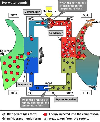
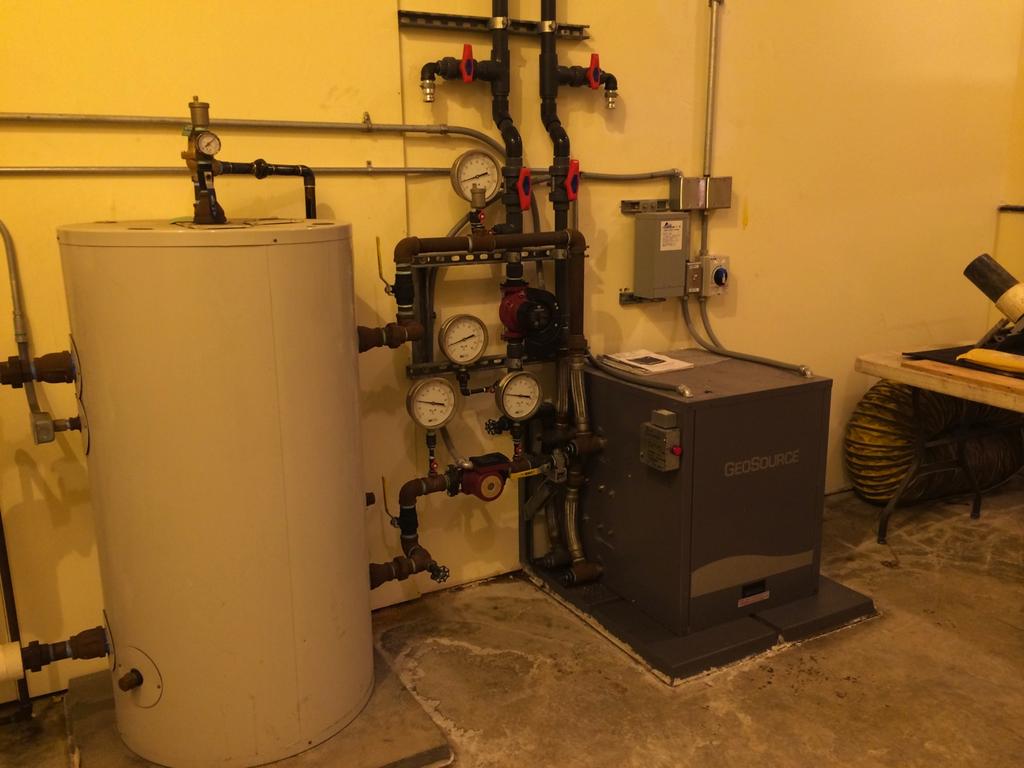
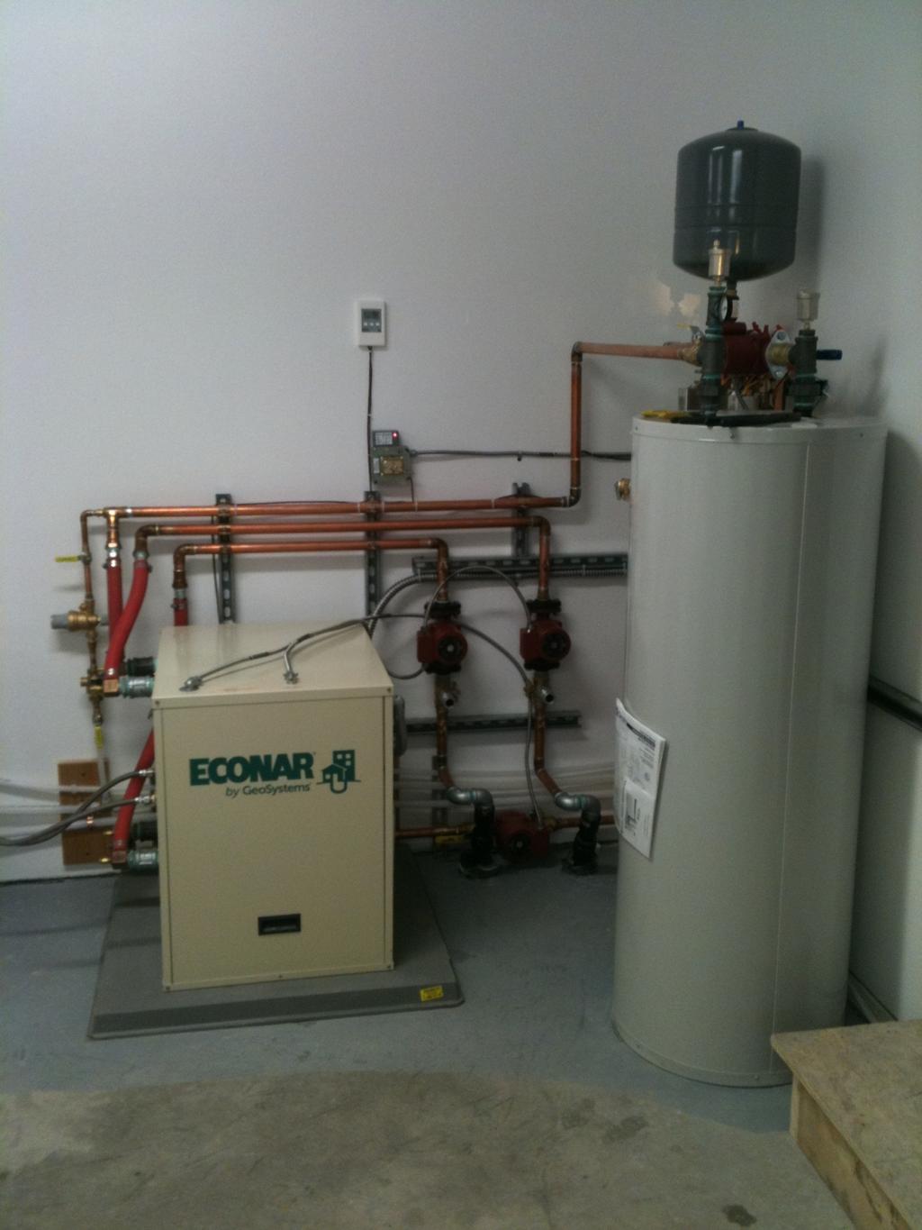
7 What is a Geothermal Heat Pump? Three components: Heat pump unit Ground loop heat exchanger Heat distribution system 7
8 8
9 9
10 Coefficient of Performance - C.O.P. l Ratio of energy delivered to energy purchased Example: C.O.P. of 3 Heat Pump Electricity 1 3 To Building 2 10 Free from Earth
11 11
12 12
13 13
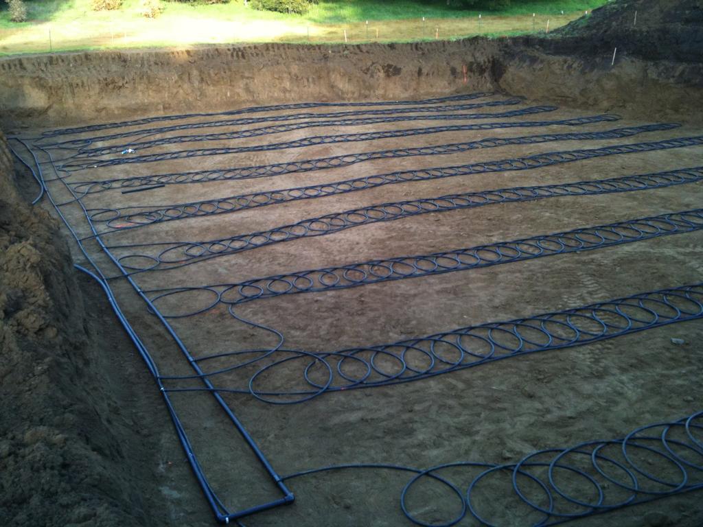
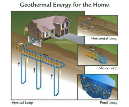
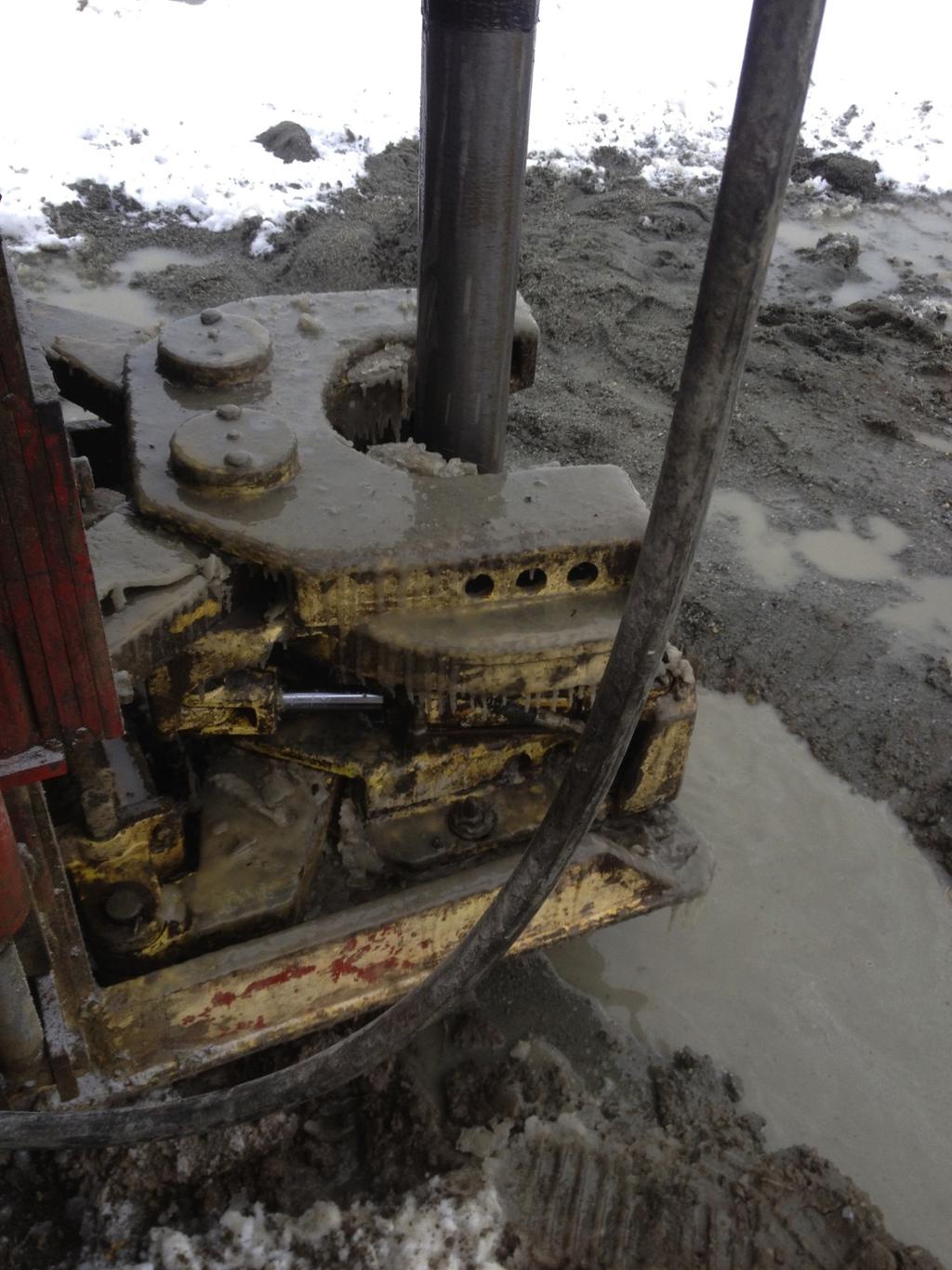
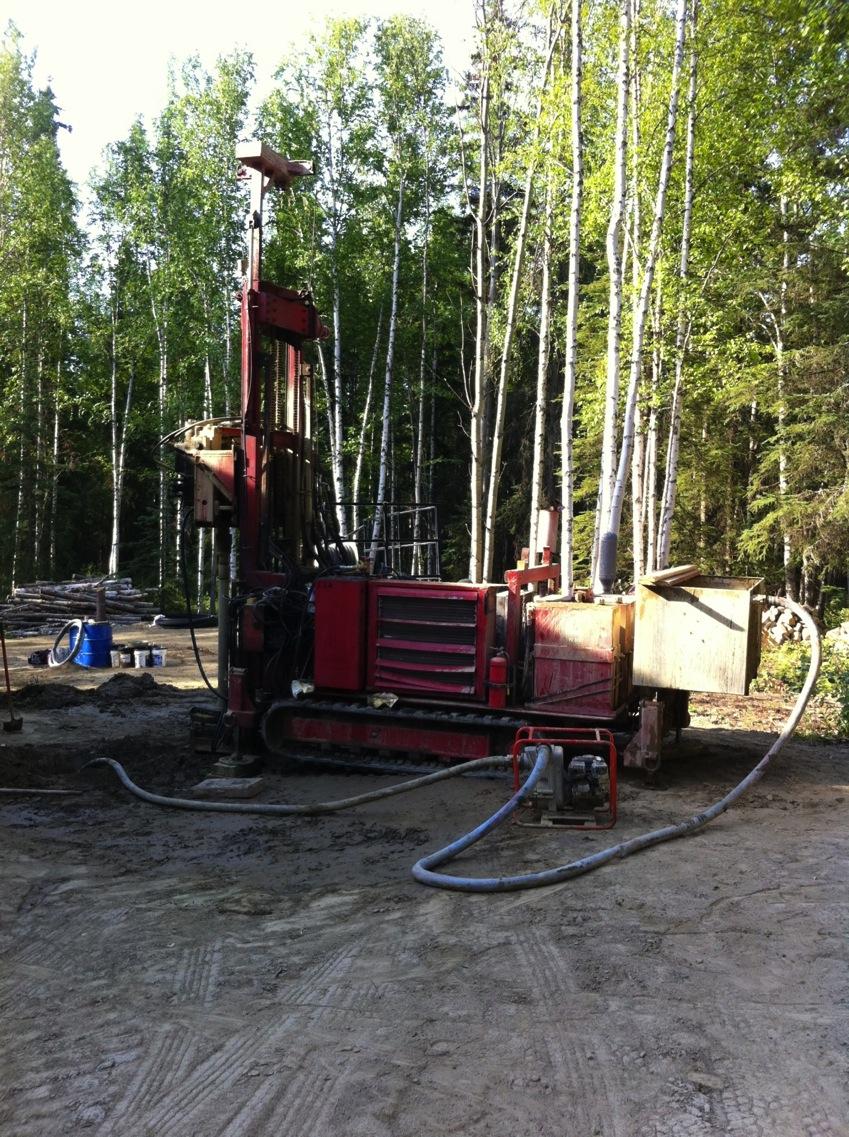
14 Installations of GHEX l All horizontal slinky loops prior to 2011 l 90% Vertical or Directional Drilled since 2011 l Reduced bore hole length per ton in some valley applications 14
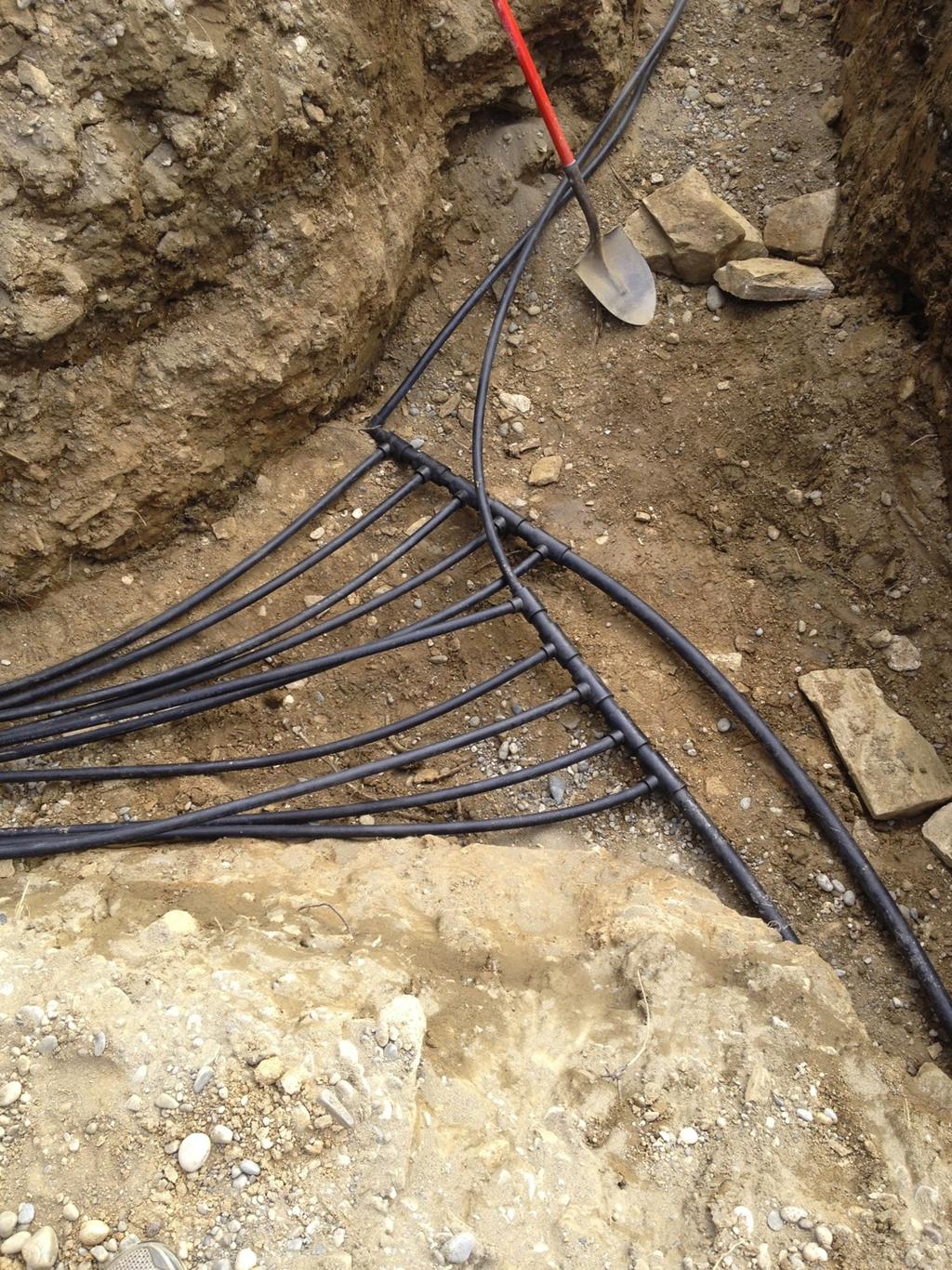
15 Typical 10-ton Horizontal System ¾" Slinky at 18" Pitch 3 ft. diameter Slinky Reverse Return Header see back for detail 1 ¼" ft. 2-3 ft. space House 2" 15 Pumping data good if total 2" header is less than 200 feet (supply & return) 80 feet long - using 600-foot Slinky Coil 100 feet long - using 800-foot Slinky Coil
16 16
17 17
18 18
19 19
20 20

21 21
22 Commercial / Industrial Examples l WV Builders - Office and Shop l NLC General - Office and Shop l Peterbuilt Truck Garage l GHU WWTP Addition l CCHRC Retrofit 22
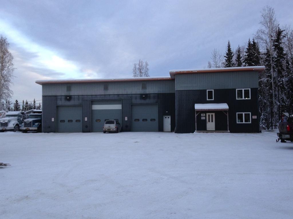
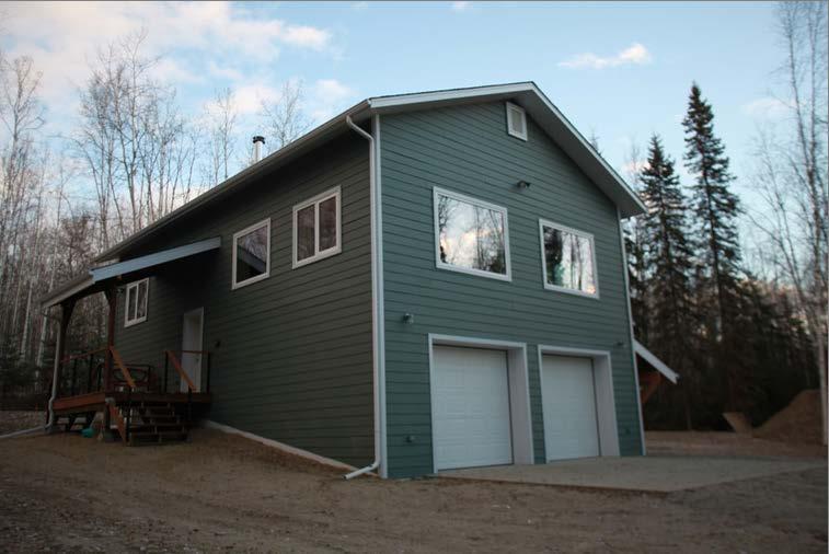
23 WV Builders Office and Shop l Built in 2012 on University Ave l 6,000 sq ft office, shop and residential appt. l 10 ton heating system with domestic h.w. 23
24 24
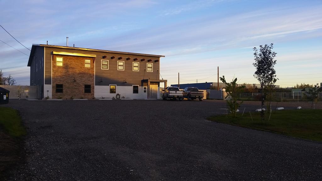
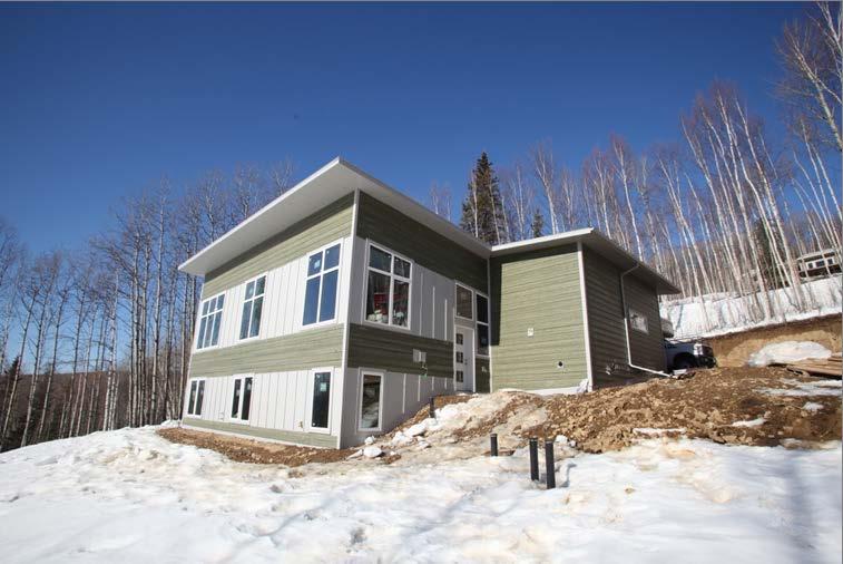
25 NLC OFFICE AND SHOP l 7,000 sq ft building near Mitchell Expressway l 60% office space and 40% shop l 10 ton hydronic heating and cooling system l 10 bore holes to
26 26
27 27
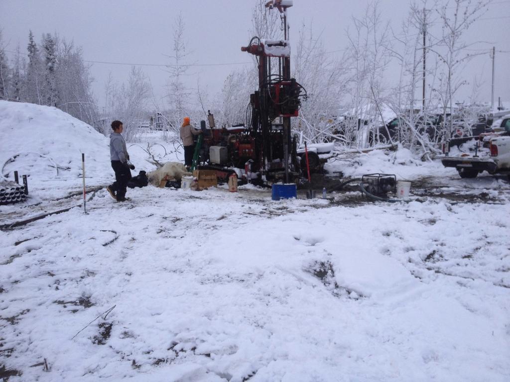
28 Peterbuilt Semi-Truck Garage l Currently being built off Van Horn Rd l 16,800 sq ft of heated garage space l 20 ton heating system l 20 bore holes to
29 29
30 30
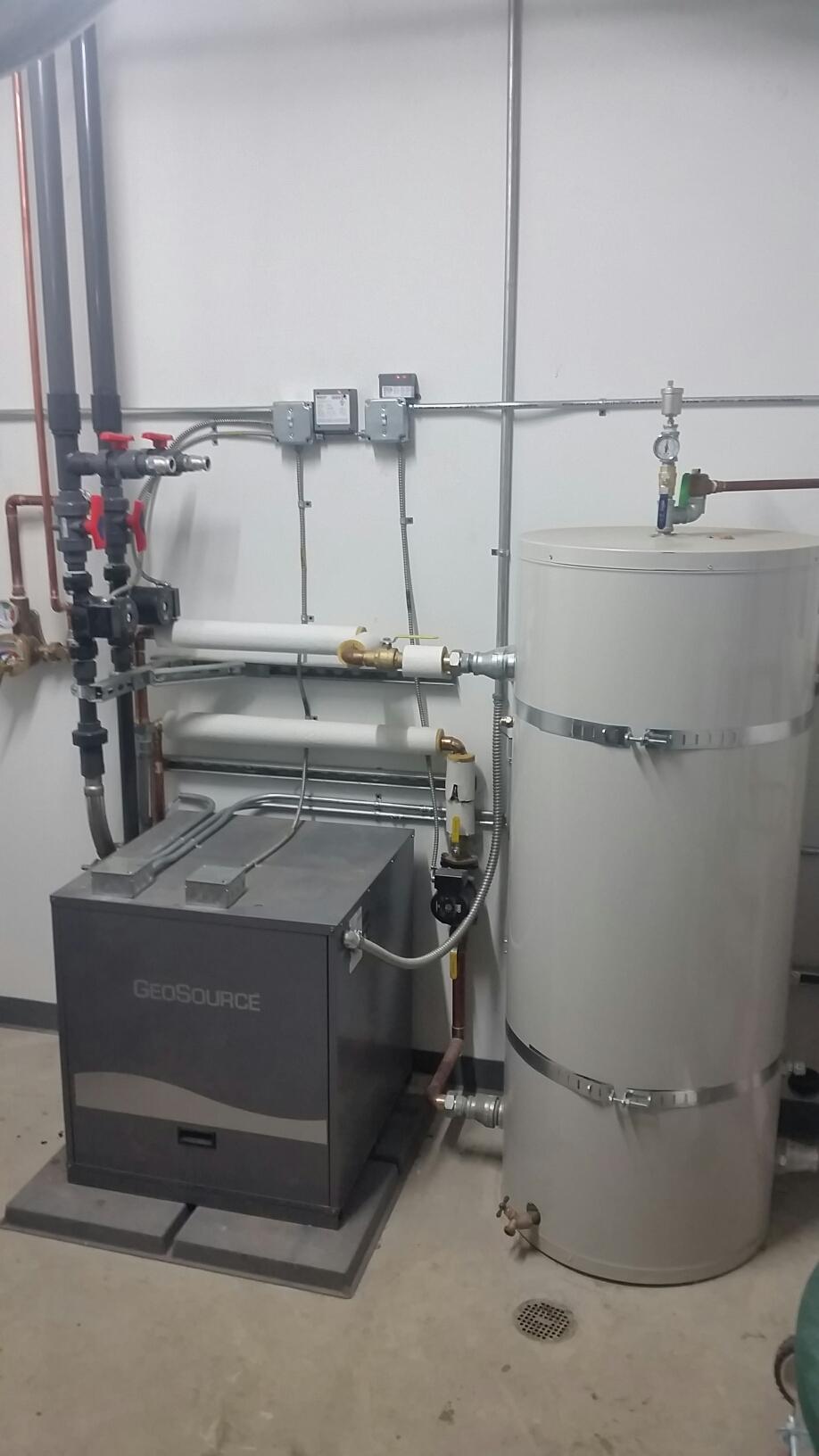
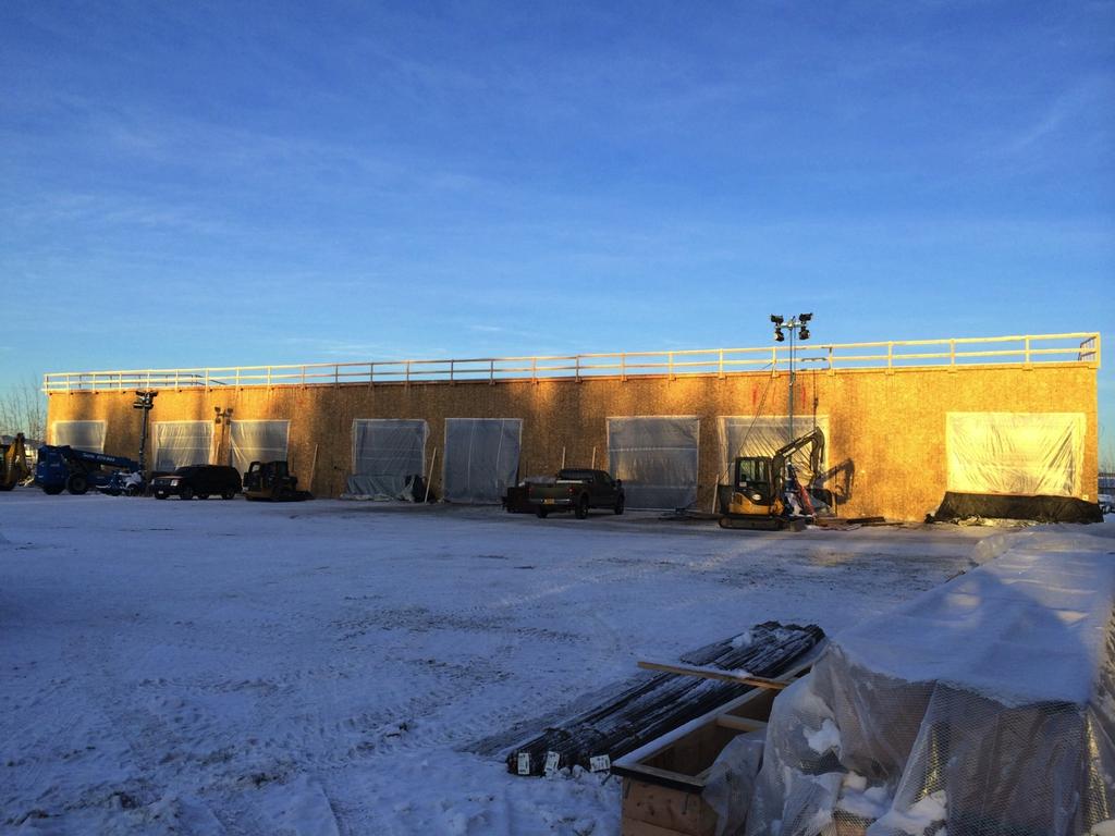
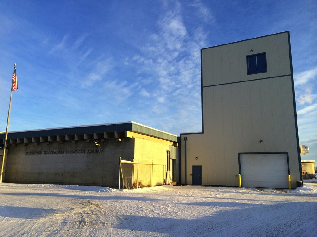
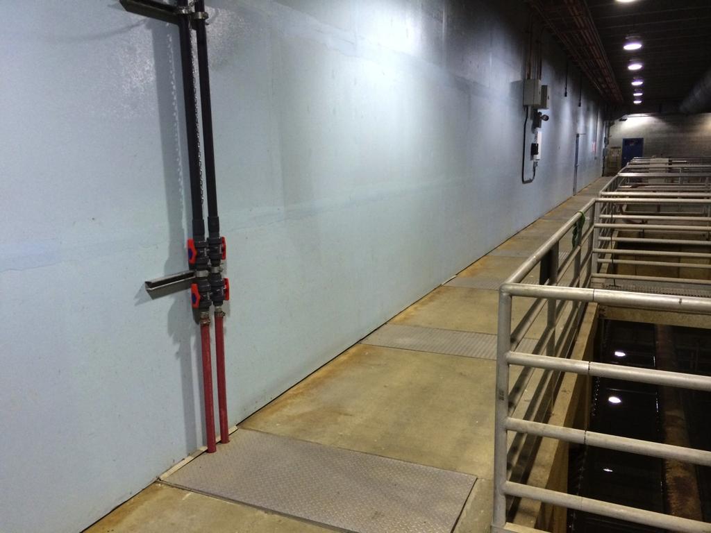
31 GHU WWTP Addition l 6 ton heat pump l Uses effluent channel as heat source l HX is one 4x8 Slim Jim l Effluent channel is 2000 gpm at 50 Deg F 31
32 32
33 33
34 34
35 CCHRC Retrofit l 6 ton heating system l Horizontal Slinky loop l Completely monitored with electrical and BTU meters l Measured C.O.P. of 3.4 to 3.6!!! l Same system as all Alaska Geothermal Residential systems 35
36 Quote From CCHRC Report Owner Satisfaction: The surveyed homeowners reported that their heat pumps are generally meeting their expectations. Many respondents noted substantial energy savings over using oil heat. Additionally, homeowners felt that the low maintenance requirements of the heat pump are an advantage, likening it to a refrigerator. Other noted advantages include not relying on the fluctuating prices of fuel, no on site combustion, and no on site fuel storage. CCHRC Ground Source Heat Pumps in Interior Alaska Lessons Learned From Installed Systems 36
37 37
38 38
39 39
40 40
41 41
42 GHP vs Heating Oil in Fairbanks l Cost for Mbtu with heating oil at $4.12 and 85% eff. Boiler = $34.95 l Cost for Mbtu with GHP with C.O.P of 3.1 and elec rates of $0.217 Kwhr = $20.52 l GHP saves 41% with current prices for energy 42
43 EPA s Take A 1993 study by the U.S. Environmental Protection Agency showed geothermal heat pumps: Provide the lowest cost heating & cooling, even when higher initial costs are factored into analysis Geothermal Heat Pumps had the lowest CO2 (greenhouse gas) emissions and the lowest over all environmental cost Can be highly cost-effective for utility conservation programs Can save home / business owners 30 to 70% annually over conventional heating systems 43
44 Greenhouse Gas Emissions l Average installation saves 5 tons per year over heating oil HL = seasonal heat load 160 GJ/yr for a modern house in Alaska FI = emissions intensity of fuel = 50 kg(co 2 )/GJ for natural gas, 73 for heating oil AFUE = furnace efficiency 95% for a modern condensing furnace COP = heat pump coefficient of performance 3.4 seasonally adjusted for Alaska heat pump EI = emissions intensity of electricity 600 ton(co 2 )/GWh, Alaska power grid 44
45 Greenhouse Gas Emissions l Average installation in Alaska saves 5 tons per year over heating oil l This is equivalent in the savings achieved by replacing 4 to 5 conventional cars with electric cars 45
46 System Design Interior Design GHEX Design 46
47 Interior Design Considerations l C.O.P. is improved with lower hot water temps Increase flow with more tubing and or slightly larger circ pumps Consider floor coverings that do not insulate Use outdoor reset controls Noise control Electrical requirements 47

48 48 Pump Curves


49 49
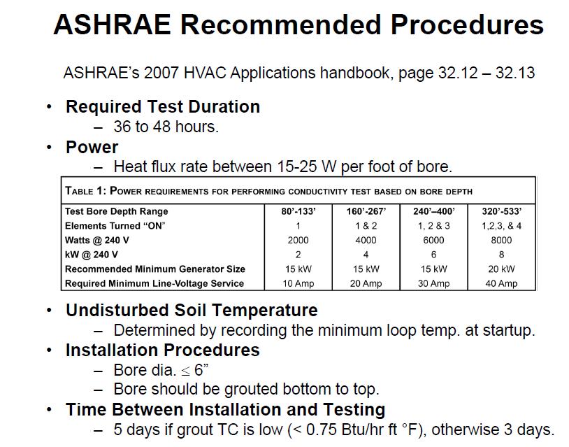
50 Design of Closed Loop Ground Heat Exchangers 50 l l l l l l l Understand piping material used, including physical characteristics, pressure ratings, flow rates for flushing and flow characteristics Understand antifreeze mixtures and properties important to GHEX design Lay out GHEX to allow ease of flushing and minimize pumping power requirements Choose best type of GHEX for site Vertically bored or horizontally trenched For GHEX over 20 tons, have a design done by a IGSHPA certified GeoExchange designer or mechanical engineer For GHEX over 20 tons, conduct a FTC test Have all systems installed by an IGSHPA certified installer
51 Determination of 3 Main Design Components l Undisturbed Formation (Ground) Temperature l Formation (Ground) Thermal Conductivity (k) A measure of a material s ability to conduct heat. l Formation (Ground) Thermal Diffusivity (a=k/ pc) Ratio of heat conduction rate to heat storage capacity 51
52 52

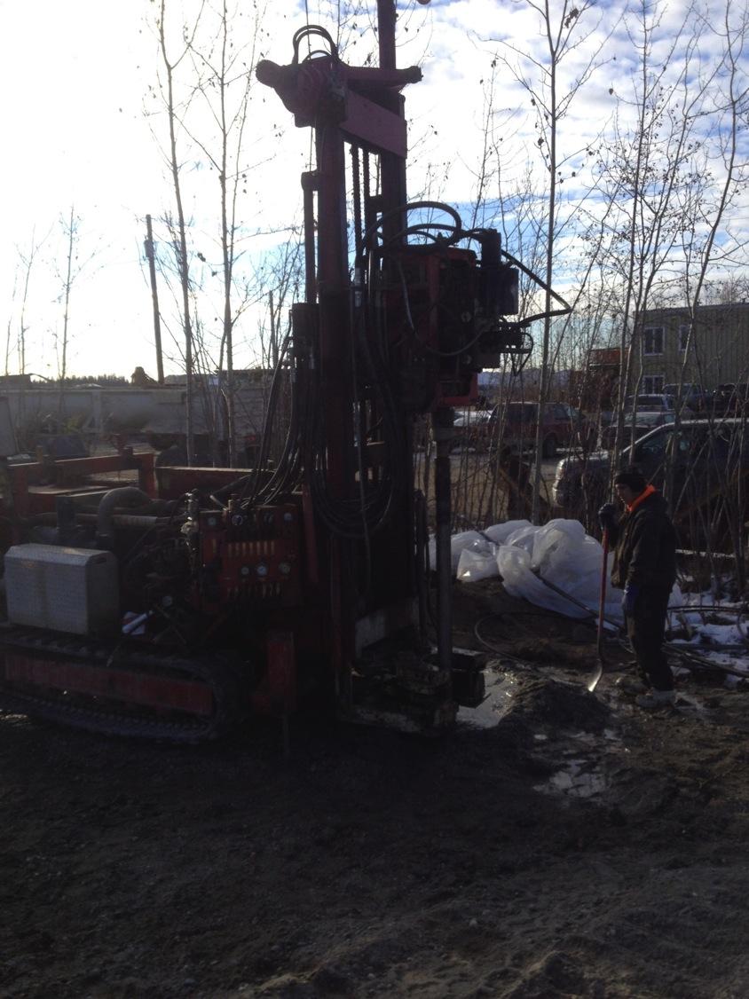
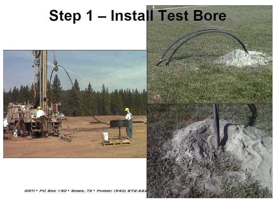
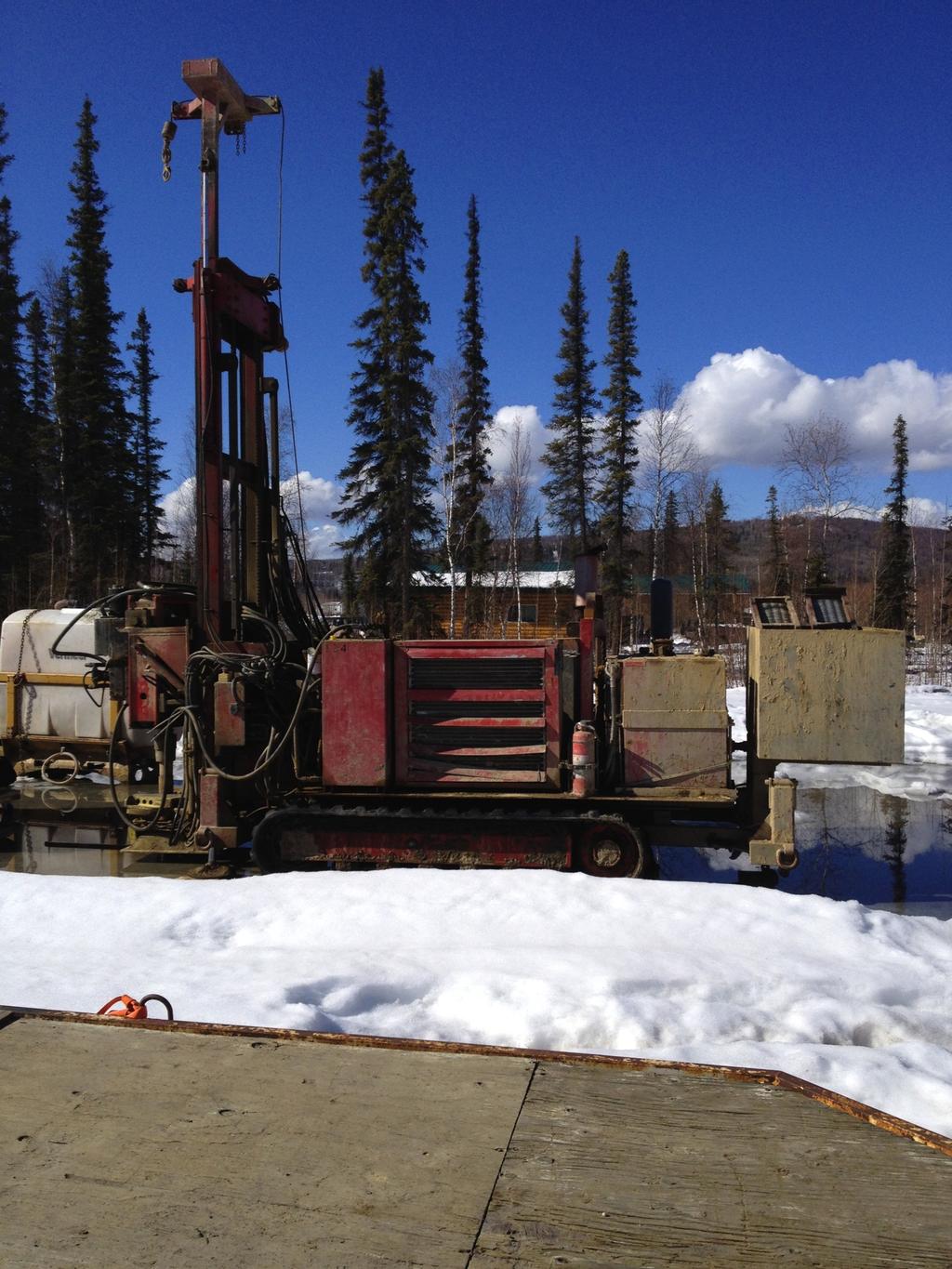
53 FTC Testing Also known as: l In-situ Testing l Thermal Conductivity Testing A field test to determine the average thermal conductivity of the formation throughout the entire length of the vertical bore column 53
54 54
55 55

56 56 Calculated (reported ) Thermal Conductivity Values
57 57
58 Different Antifreezes have Different Properties l Methanol Inexpensive Excellent thermal conductivity Somewhat toxic Low viscosity l Propylene Glycol 58 Safest Thick at cold temps Poor thermal conductivity Expensive
59 Flow in GHEX 59 l Want a flushing flow rate greater than 2 ft/sec in pipe to purge all air. l Want turbulent flow during normal system operation to maximize heat transfer Reynolds Number > 2500 Use Reynolds Number tables for HDPE pipe sizes with proper antifreeze correction factors to decide min flow rate Use the greater flow rate between this value and heat pump flow requirement
60 60
61 General GHEX Design Procedure l Select a GHEX configuration for the site l Configure the GHEX for proper flow and ease of flushing l Estimate the length of each flow path in the GHEX l Calculate the head loss to size the pumping system l Evaluate the economics of the design l Redesign, if necessary or consider other configurations 61
62 Vertical Heating Design Equations Lht = HCD x ((COP 1)/COP) x RB + RG x FH TG ((EWTmin + LWTmin) / 2) l l l l Lht = total borehole design length for heating (below header trench), ft HCD = heat pump heating capacity at design heating conditions, Btu/hr COPD = coefficient of performance at design heating conditions, dimensionless RB = borehole thermal resistance, hr ft F/Btu l RG = steady-state thermal resistance of ground surrounding the borehole, hr ft F/ Btu l l l l FH = run fraction in heating mode during heating design month (Jan) dimensionless TG = average ground temperature along borehole length, F EWT = minimum entering water temperature at heating design conditions, F LWT= minimum leaving water temperature at heating design conditions, F 62
63 Horizontal heating Design Equation LHP = HCD x ((COPD 1)/COPD) x (RP + RS x PM x SM x FH) TSL ((EWTmin + LWTmin) / 2) 63 l l l l l LHP = total pipe design length for heating, ft HCD = heat pump heating capacity at design heating conditions, Btu/hr COPD = coefficient of performance at design heating conditions, dimensionless RP = pipe thermal resistance, hr ft F/Btu Rs = steady-state thermal resistance of soil, hr ft F/Btu l PM = multiplier to account for pipe diameter other than ¾ l l l l l SM = multiplier to account for trench spacing FH = run fraction in heating mode during heating design month (Jan) dimensionless TSL = design soil temperature for heating at average GHEX pipe depth, F EWT = minimum entering water temperature at heating design conditions, F LWT= minimum leaving water temperature at heating design conditions, F
64 Many Different Options Available l Hydronic -- low temp heat & chilled water. l Stand alone domestic hot water. l Forced air -- vertical, horizontal l Forced air / on demand domestic hot water. l Forced air / hydronic combination. l Forced air / two stage compressor. l Accessories for turn key installations. 64
65 65 Thank You for Your Time
66 References l en.wikipdia.org (EPA study) l (public website) l (dealers & distributors) l (Department of Energy) l (third party HX performance verification) l 66