AFRL-ML-WP-TR
|
|
|
- Berniece Wells
- 5 years ago
- Views:
Transcription
1 AFRL-ML-WP-TR RESEARCH AND DEVELOPMENT (R&D) ON ADVANCED NONSTRUCTURAL MATERIALS Delivery Order 0001: Cleaning Efficiency Study of Malabar International and Pall Corporation Portable Fluid Purifiers Carl E. Snyder, Jr.; Shashi K. Sharma; and Lois Gschwender Nonstructural Materials Branch (AFRL/MLBT) Nonmetallic Materials Division Materials and Manufacturing Directorate Air Force Research Laboratory, Air Force Materiel Command Wright-Patterson AFB, OH George W. Fultz and Timothy Jenney University of Dayton Research Institute OCTOBER 2005 Final Report for 01 August November 2004 Approved for public release; distribution unlimited. STINFO FINAL REPORT MATERIALS AND MANUFACTURING DIRECTORATE AIR FORCE RESEARCH LABORATORY AIR FORCE MATERIEL COMMAND WRIGHT-PATTERSON AFB, OH
2 NOTICE Using Government drawings, specifications, or other data included in this document for any purpose other than Government procurement does not in any way obligate the U.S. Government. The fact that the Government formulated or supplied the drawings, specifications, or other data does not license the holder or any other person or corporation; or convey any rights or permission to manufacture, use, or sell any patented invention that may relate to them. This report was cleared for public release by the Air Force Research Laboratory Wright Site Public Affairs Office (AFRL/WS) and is releasable to the National Technical Information Service (NTIS). It will be available to the general public, including foreign nationals. Public Affairs case number: AFRL-WS Date cleared: 19-July-2005 THIS TECHNICAL REPORT IS APPROVED FOR PUBLICATION. //s// LOIS GSCHWENDER, Project Engineer Nonstructural Materials Branch Nonmetallic Materials Division //s// JEFFREY H. SANDERS, Chief Nonstructural Materials Branch Nonmetallic Materials Division //s// PERSIS A. ELWOOD, Deputy Chief Nonmetallic Materials Division Materials and Manufacturing Directorate This report is published in the interest of scientific and technical information exchange and its publication does not constitute the Government s approval or disapproval of its ideas or findings.
3 REPORT DOCUMENTATION PAGE Form Approved OMB No The public reporting burden for this collection of information is estimated to average 1 hour per response, including the time for reviewing instructions, searching existing data sources, searching existing data sources, gathering and maintaining the data needed, and completing and reviewing the collection of information. Send comments regarding this burden estimate or any other aspect of this collection of information, including suggestions for reducing this burden, to Department of Defense, Washington Headquarters Services, Directorate for Information Operations and Reports ( ), 1215 Jefferson Davis Highway, Suite 1204, Arlington, VA Respondents should be aware that notwithstanding any other provision of law, no person shall be subject to any penalty for failing to comply with a collection of information if it does not display a currently valid OMB control number. PLEASE DO NOT RETURN YOUR FORM TO THE ABOVE ADDRESS. 1. REPORT DATE (DD-MM-YY) 2. REPORT TYPE 3. DATES COVERED (From - To) October 2005 Final 08/01/04 11/30/04 4. TITLE AND SUBTITLE RESEARCH AND DEVELOPMENT (R&D) ON ADVANCED NONSTRUCTURAL MATERIALS Delivery Order 0001: Cleaning Efficiency Study of Malabar International and Pall Corporation Portable Fluid Purifiers 6. AUTHOR(S) Carl E. Snyder, Jr.; Shashi K. Sharma; and Lois Gschwender (AFRL/MLBT) George W. Fultz and Timothy Jenney (University of Dayton Research Institute) 5a. CONTRACT NUMBER F D b. GRANT NUMBER 5c. PROGRAM ELEMENT NUMBER 62102F 5d. PROJECT NUMBER e. TASK NUMBER 60 5f. WORK UNIT NUMBER FK 7. PERFORMING ORGANIZATION NAME(S) AND ADDRESS(ES) 8. PERFORMING ORGANIZATION REPORT NUMBER Nonstructural Materials Branch (AFRL/MLBT) Nonmetallic Materials Division Materials and Manufacturing Directorate Air Force Research Laboratory, Air Force Materiel Command Wright-Patterson AFB, OH University of Dayton Research Institute 9. SPONSORING/MONITORING AGENCY NAME(S) AND ADDRESS(ES) 10. SPONSORING/MONITORING AGENCY ACRONYM(S) Propulsion Directorate Air Force Research Laboratory Air Force Materiel Command Wright-Patterson AFB, OH DISTRIBUTION/AVAILABILITY STATEMENT Approved for public release; distribution is unlimited. 13. SUPPLEMENTARY NOTES Report contains color. AFRL/MLBT 11. SPONSORING/MONITORING AGENCY REPORT NUMBER(S) AFRL-ML-WP-TR ABSTRACT Hydraulic fluids are a critical, safety-of-flight material for all Air Force aircraft. Hydraulically actuated mechanisms are responsible for a large number of aircraft functions ranging from highly sophisticated flight controls to applications such as accessory door actuation. The Air Force alone uses approximately 1,000,000 gallons of hydraulic fluid per year, costing over $12M in procurement and disposal costs. Used hydraulic fluid currently is the second largest waste stream for the Air Force. In the past, hydraulic fluid purification or reclamation for reuse was not permitted in aircraft systems. The Air Force technical order covering hydraulic fluids was recently changed to allow reintroduction of purified fluid into aircraft. Purifiers from Pall Corp and Malabar International were tested at the Hydraulic Pump Testing Facility at the Materials and Manufacturing Directorate to determine the removal rates of particulate, water, and dissolved air from MIL-PRF hydraulic fluid to a predetermined level. The program goal was to see the rates at which these purifiers would remove particulates to NAS 1638 Class 5 maximum, water to 100 ppm maximum, and dissolved air to 8% by volume maximum. 15. SUBJECT TERMS hydraulic fluids, purification, reclamation, Pall Corporation, Malabor International 16. SECURITY CLASSIFICATION OF: 17. LIMITATION 18. NUMBER 19a. NAME OF RESPONSIBLE PERSON (Monitor) OF ABSTRACT: OF PAGES SAR 32 a. REPORT Unclassified b. ABSTRACT Unclassified c. THIS PAGE Unclassified Lois Gschwender 19b. TELEPHONE NUMBER (Include Area Code) (937) Standard Form 298 (Rev. 8-98) Prescribed by ANSI Std. Z39-18 i
4 Cleaning Efficiency Study of Malabar International and Pall Corp. Portable Fluid Purifiers George W. Fultz and Timothy Jenney University of Dayton Research Institute Carl E. Snyder, Jr., Shashi K. Sharma and Lois Gschwender AFRL/MLBT 1.0 INTRODUCTION Hydraulic fluids are a critical, safety-of-flight material for all Air Force aircraft. Hydraulically actuated mechanisms are responsible for a large number of aircraft functions ranging from highly sophisticated flight controls to applications such as accessory door actuation. The Air Force alone uses approximately 1,000,000 gallons of hydraulic fluid per year, costing over $12 million in procurement and disposal costs. Used hydraulic fluid currently is the second largest waste stream for the Air Force. Presently, during routine aircraft maintenance, the used fluid from aircraft and components is drained and disposed of as hazardous waste. Previously, hydraulic fluid purification or reclamation for reuse was not permitted in aircraft systems. But, the Air Force technical order (TO) covering hydraulic fluids (T.O. 42B2-1-3, Fluids for Hydraulic Equipment) was recently changed to allow reintroduction of purified fluid into aircraft. The approved purifiers and other specific instructions are detailed in T.O. 42B Two model 8852 Malabar International fluid purifiers were delivered to the Air Force Aircraft Hydraulic Pump Testing Facility located in the Materials and Manufacturing Directorate of the Air Force Research Laboratory at Wright Patterson Air Force Base. Soon these two purifiers as well as two Pall Corp. Model PE Z portable fluid purifiers will be sent to predetermined Air Force bases to determine the 1
5 effect of the implementation of hydraulic fluid purification on: 1. Hydraulic fluid waste stream reduction; 2. Maintenance work load; 3. Hydraulic component life extension; 4. Hydraulic system performance. Both of these purifiers have previously been determined to have no adverse effect on hydraulic fluid performance properties as they both employ physical processes to remove the contaminants and do not remove any performance improving additives. (References 1, 2, 3) In all three of the referenced documents the main point of the tests was to verify that the purification processes evaluated were not harmful to the hydraulic fluids. However, no testing was conducted to determine the cleaning efficiency of the two different purifiers with regard to their ability to remove particulate, water and dissolved air. Purifiers from Pall Corp. and Malabar International were tested to determine the removal rates of particulate, water and dissolved air from MIL-PRF hydraulic fluid to a predetermined level. The program goal was to see the rates at which these purifiers would remove particulates to NAS 1638 Class 5 maximum, water to 100 ppm maximum and dissolved air to 8% by volume maximum. Also an experiment was conducted to determine if either of these purifiers would remove JP-8 jet fuel from MIL-PRF PURIFIERS EVALUATED The Pall Corporation hydraulic fluid purifier, model PE Z, uses a spinning disk to generate high fluid surface area. See Figure 1. The volatiles (moisture and solvents) are removed by vacuum in the purifier chamber, and the particulates are removed by a high-efficiency filter. (See Ref. 1 and 2 for details.) Malabar International s model 8852 hydraulic fluid purifier is a portable standalone misting-type purifier, similar in function to the prototype purifier built in their new hydraulic test stand. See Figure 2. Fluid misting generates high surface area for the fluid which facilitates removal of volatile contaminants in the chamber vacuum. The particulates are removed by a high efficiency filter (See Ref. 3 for details). Changes from the prototype included the absence of a metering valve, an added low watt density heater, a smaller reservoir, and an internal circulation system. This portable stand-alone purifier design integrated a fully covered rolling enclosure, a microprocessor control panel, 2
6 controls for flow, temperature and vacuum, audio and visual alarms, a moisture sensor with go / no-go indicators and ppm water readings, and a particulate sensor with go / nogo indicators and ISO particulate contamination level readout. 3.0 PURIFICATION PROCEDURE 3.1. Closed Loop It was thought that a closed loop system was needed so the rate of removal of dissolved air could be measured more accurately. An open loop system could allow air from outside interfere with measuring the rate of removal of dissolved air. Figure 3 shows the closed loop hydraulic circuit flowing in series through two heat exchangers (both non-functional to increase the total system volume) and one stainless steel movable piston reservoir. The loop was configured to enable either a Teflon piston stir pump loop or the purifier loop to be in series with the circuit. A shunt valve (V3) was connected between the inlet and outlet of the purifier, and a sampling septum (P1) was added to the purifier outlet for collecting samples using gas tight syringes. The samples in the syringe were measured for dissolved air content using capillary gas chromatography. A needle valve sampling port (P2) for filling bottles was inserted between the movable piston reservoir and the heat exchangers. A reservoir pressure gauge tracked system pressure and the entire circuit was connected with Teflon-lined stainless steel braided hose. Total fluid volume of the entire system was 25 gallons, divided into 20 gallons within the closed loop hydraulic circuit and 5 gallons within the specimen purifier reservoir. A photo of the Pall Corporation hydraulic fluid purifier connected to the closed loop can be seen in Figure 4 and a photo of the Malabar International connected to the closed system can be seen in Figure 5. The purifier and heat exchangers were drained of the residual MIL-PRF that wetted the internal mechanisms / plumbing for storage purposes. The stir pump, braided connection hose, and reservoir were rinsed with solvent and flushed with fresh MIL-PRF-83282, as were the valves and fittings. After assembly and filling with fresh MIL-PRF-83282, both the stir pump loop and specimen purifier loop circulated simultaneously, just enough to purge free air. At this point, the purifier was isolated from 3
7 the closed loop hydraulic circuit and by-passed, leaving 5 gallons of a clean fluid charge in the specimen purifier reservoir. This priming of the purifier is representative of the initial operational state of the purifier in the field Vented Loop A similar loop design as was used for the closed system in Figure 3 was also used for the vented system. By simply venting the closed loop it would better simulate actual field conditions where the ground carts and mules are vented. Atmosphere was allowed to enter and exit the loop whenever the fluid volume of the loop would change. The requirement to change the fluid volume for the vented loop tests came from the displacement of fluid from the Malabar purifier, which occasionally pumps out its own reservoir as an inherent part of the purification process. This step occurred only during the vented system tests. The volume of the fluid in the purification chamber of the Malabar purifier is controlled by two sensors. There is a sensor near the bottom of the purification chamber that closes after the purified fluid is re-introduced into the recirculating system. Once the fluid in the chamber has been purified (fluid misting using a spray nozzle), there is a sensor near the top of the purification chamber that closes and sends a signal to the bottom sensor to open (stops the misting) and add the purified fluid to the recirculating system. The two primary physical differences between each loop type included relocating the reservoir outlet to the bottom center of the reservoir tank base, and replacing the pressure gauge with a valve and graduated cylinder assembly. Placing the reservoir discharge siphon underneath ensured the continuous submersion of the reservoir drain. The valve and graduated cylinder assembly permitted control of the airflow in and out of the reservoir if needed, and also provided the capability, if necessary, to seal the graduated cylinder (for example to measure contaminants before adding). By mounting the vent on the circuit reservoir lid, air could exchange places with the fluid without drawing free air through the connecting lines. These modifications to the closed loop changed the volume of the test fluid in the loop and inside the purifier tank. A photograph of these changes is shown in Figure 6. The total fluid quantity of the entire system (vented loop plus the purifier fill) was 4
8 reduced to 18 gallons. Less fluid was used because the purifier tank would fill and empty (~ 7 gallons) during the purifying process, differing from the unvented loop where the purifier tank was held in a steady state and the total fluid quantity was 25 gallons. While this was not required to accommodate the Pall purifier, the fluid volume was maintained at 18 gallons for the Pall purifier test to have an effective comparison while testing purifier performance with the vented loop configuration Contamination Procedure The contaminants were added, approximately 35 ml of distilled water first, by pressure injection with a syringe into the reservoir, while bleeding the excess volume from the needle valve sampling port. Approximately 8 ounces of slurry (a mix of fresh MIL-PRF and A/C fine dust) were added to the 20 gallons of MIL-PRF for the closed loop system and 13 gallons of MIL-PRF for the vented system. These amounts targeted excessive contamination levels compared to those expected in the field, to more than 500 ppm water content and to a maximum NAS 1638 particulate contamination class of 12. The pneumatically driven Teflon piston stir pump loop was opened (V2) and its by-pass line closed (V1), V3 was opened and V4 and V5 were closed. The fluid and contaminants were mixed by passing the fluid through the loop at a circulation rate of about 12 to 15 gallons per minute. Fluid samples were taken periodically and measured for contaminant levels. This mixing continued until sampled values for water content and particle count were consistent and approached the desired measured levels. When completed, the stir pump loop was isolated (V2 closed) and by-passed, and the specimen purifier loop was opened (V1) and the corresponding by-pass line (shunt valve V3) closed. Valves 4 and 5 at the purifier were opened. Purification was then initiated and hourly fluid samples for dissolved air content, water content, and particle count were drawn. The maximum acceptable purification running time was set to 8 hours to purify the fluid, as described in the introduction, to NAS 1638 particulate contamination class 5 or better, to water content of 100 ppm or less, and to dissolved air to 8 percent or less. 5
9 To determine if the portable purifiers could remove JP-8 fuel from hydraulic fluid MIL-PRF was contaminated with approximately 17% JP-8 using the same mixing procedure described in the previous paragraph. Both the Pall Corp. and Malabar International purifiers were tested, using the same procedure as described in section 3.1, to determine if JP-8 could be removed 4.0 TEST RESULTS 4.1 Pall Corp. Purifier Using the contamination procedure in 3.3 the 0 hour measured particulate count was NAS 1638 class 12, the water was 725 ppm and the dissolved air was at 11.8%. The data from the closed loop purification test is shown in Table 1. After only one hour all the contamination levels were down to or below the limits set for the test. It was decided to run the purifier for three more hours and at each hour measure the particulates, water, and dissolved air. The particulate count and dissolved air did not significantly change after the first hour, but the water content continued to drop. This same contamination and operating procedures were used with the vented system. The contamination levels, however, were slightly different. The water contamination was 1020 ppm for the vented system compared to 725 ppm for the closed system. The dissolved air was 12.8% for the vented system compared to 11.8% for the closed system. The particle count was a NAS 1638 class 12 for both systems. The results which are similar to those from the closed system are shown in Table 2. JP-8 in hydraulic fluid was measured using a capillary gas chromatograph (GC) method shown in Table 3. Standards containing JP-8 in MIL-PRF were analyzed and Figure 5 shows the least square best fit for the GC measurements. This least square formula was used to determine the unknown concentrations of JP-8 in MIL-PRF The purifier was contaminated with approximately 17% JP-8 using the procedure described in 3.3. This fluid was passed through the Pall Corp. purifier for eight hours and essentially no JP-8 was removed. The results are shown in Table 4. 6
10 4.2 Malabar International Procedure During preliminary testing the Malabar International model 8852 purifier, unlike Malabar International prototype (3), was unable to function using a fixed fluid volume within the closed evaluation circuit. This shortcoming of the model 8852 Malabar International purifier was resolved by installing an adjustable spray metering needle valve to the purifier as per the prototype. The same procedure for contamination was used as in the section 3.3. With the pressure problem solved the purification test was started. The data is shown in Table 5. After only one hour all the measured contamination levels were down to or below the limits set for the test except the water content that was 295 ppm. Four hours were required for the water content to be reduced below 100 ppm. The test was continued for an extra hour to determine how much more water could be removed and as shown in the water was reduced to 69 ppm. Because it took longer for the Malabar International purifier compared to the Pall Corp. purifier for water to go below 100 ppm, it was decided to repeat the test, for water only, while activating the heating option on the Malabar International purifier. The heater was set to the recommended manufacturer s set point position of 125 F. However, the actual fluid temperature remained at approximately 85 F throughout the test according to the temperature readout on the purifier panel. The data in Table 6 shows that water was not removed any quicker when using the heating option. In both tests, the Malabar International water sensor tracked well with the Karl Fisher titrations conducted on the samples at levels below 500 ppm water, the maximum amount of water that is soluble in MIL-PRF hydraulic fluid. The same procedure (without the heater) was used with the vented system. However with the vented system there was no need for the adjustable spray metering needle valve. The results are shown in Table 7. After five hours the water did not go below 184 ppm. However, the particulate NAS 1638 and dissolved air removal were similar to the closed system results. The purifier was contaminated with approximately 17% JP-8 using the procedure described in 3.3. The percent of JP-8 was measured by GC as described in 4.1. This 7
11 fluid was passed through the Malabar International purifier for eight hours and essentially no JP-8 was removed. The results are shown in Table CONCLUSIONS Both the Pall Corp. and Malabar International purifiers achieved the goal of reducing contaminants to specific limits in the closed system after four hours. See Figures 8 through 10. The Pall Corp. purifier was able to remove contaminants below the target value of NAS 1638 Class 5 in one hour and water to below 100 ppm in one hour. The Malabar International purifier was also able to remove the particulate contaminants below the target value of NAS 1638 Class 5 in one hour, but it took four hours to get the water below 100 ppm. Dissolved air was significantly reduced from initial saturation (~12%) for both purifiers to less than two percent in two hours. The Malabar International purifier heating unit was applied in a second run, but did not help remove water any faster than in the closed system. Neither purifier was able to remove JP-8 fuel. Both the Pall Corp. and Malabar International purifiers tested achieved the goal of reducing particulates contaminants and dissolved air to specific limits in the vented system after four hours. See Figures 11 through 13. However, the Malabar International purifier only removed water to a level of 184 ppm after four hours in the vented mode of operation and the vented system testing was conducted with a smaller volume of fluid than the closed system test (18 vs. 25 gallons). 6.0 REFERENCES 1) AFRL-ML-WP-TR , Endurance Pump Tests with Fresh and Purified MIL-H-5606 Hydraulic Fluid June ) AFRL-ML-WP-TR , Endurance Pump Tests with Fresh and Purified MIL-PRF Hydraulic Fluid September


12 3) AFRL-ML-WP-TR , Endurance Pump Test with MIL-PRF Hydraulic Fluid, Purified with Malabar International Purifier, June 2004 ACKNOWLEDGEMENTS We appreciate Charles Tobin and Timothy Reid, both of the University of Dayton Research Institute, who were invaluable in obtaining the sampling data. Figure 1. Pall Purifier 9


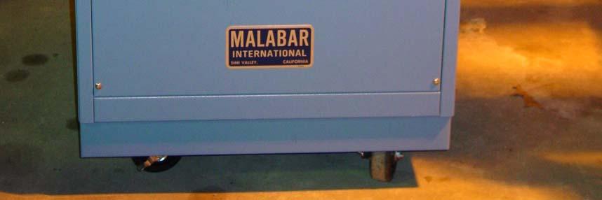
13 Figure 2. Malabar Purifier 10
14 Figure 3. Schematic of Pumping Loop EXCHANGER 2 P2 SAMPLING PORT & AIR BLEED V3 (PURIFIER SHUNT & BYPASS VALVE) V4 EXCHANGER 1 SPECIMEN PURIFIER STIR PUMP V1 V2 MOVABLE PISTON RESERVOIR P1 V5 SAMPLING SEPTUM 11


15 Figure 4. Pall Corp. Purifier Connected to Closed System Pumping Loop Pall Purifier P1 V4 V4 V5 Heat Exchanger 2 P1 V2 Movable Piston Reservoir V1 V3 Heat Exchanger 1 Stir Pump 12

16 Figure 5. Malabar International Purifier Connected to Closed Pumping Loop Malabar Purifier <P1 V4 V5 P1 Movable Piston Reservoir V2 V1 V3 13

17 Figure 6. Vented System Reservoir Graduated Cylinder Vent Inlet 14
18 Table 1. Samples from Pall Corp. Closed System Purification Test PURIFICATION TIME (HRS) FLUID PROPERTY MIL-PRF LIMITS BEFORE CONTAMINANTS MLO NUMBER PARTICLE COUNT 5-15 microns 10,000 70, ,295 3,190 4,290 3,535 3, microns 1,000 6, , microns , microns , >100 microns NAS WATER, PPM 100 MAX PERCENT AIR by GC Not Applicable
19 Table 2. Samples from Pall Corp. Purification Vented System Test ` FLUID PROPERTY MIL-PRF LIMITS PURIFICATION TIME (HRS) BEFORE CONTAMINANTS MLO NUMBER PARTICLE COUNT 5-15 microns 10,000 1, ,355 6,985 6,030 5,620 5, microns 1, , microns , microns , >100 microns 5 0 1, NAS WATER, PPM 100 MAX PERCENT AIR by GC Not Applicable Table 3. Gas Chromatography Conditions for JP-8 in MIL-PRF Oven Temperature 150 C hold for 4 min, ramp 16 C/min to 270 C Injector Temperature Detector Temperature Column Type 300 C 350 C Capillary fused silica Column Length 12 meters Column Diameter 0.22 millimeters Column Liquid phase Methyl Silicone Carbowax Deactivated packed column Sample Size 1.0 microliter 16
20 Figure 7. Least Square Fit for JP-8 in MIL-PRF ,000,000 5,000,000 4,000,000 GC Area 3,000,000 2,000,000 Run 1 Run 2 Linear (Run 1) Linear (Run 2) 1,000, ,000, % JP8 17
21 Table 4. Pall Corp. JP-8 Removal by Purifier DATE SAMPLE % JP-8 9/14/04 0 HOUR /15/04 1 HOUR /15/04 2 HOUR /15/04 3 HOUR /15/04 4 HOUR /15/04 5 HOUR /15/04 6 HOUR /15/04 7 HOUR /15/04 8 HOUR 17.8 Table 5. Samples from Malabar International Closed System Purification Test PURIFICATION TIME (HRS) MIL-PRF BEFORE FLUID PROPERTY LIMITS CONTAMINANTS MLO NUMBER PARTICLE COUNT 5-15 microns 10,000 11,755 1,861,295 4,000 4,860 4,980 6,020 3, microns 1, ,407, microns , microns , >100 microns , NAS WATER, PPM 100 MAX WATER, PPM (MAL. Meter) PERCENT AIR by GC Not Applicable
22 Table 6. Water Data from Using Heater in Malabar International Purifiers MIL-PRF BEFORE WATER FLUID PROPERTY LIMITS CONTAMINANTS MLO NUMBER WATER, PPM 100 MAX WATER, PPM (MAL. Meter) Table 7. Samples from Malabar International Vented System Purification Test PURIFICATION TIME (HRS) MIL-PRF- BEFORE FLUID PROPERTY LIMITS CONTAMINANTS MLO NUMBER PARTICLE COUNT 5-15 microns 10,000 1, ,465 56,365 3,970 7,585 4,250 a microns 1, ,590 12, a microns ,535 4, a microns , a >100 microns a NAS a WATER, PPM 100 MAX WATER, PPM (MAL. Meter) a PERCENT AIR by GC Not Applicable a a - not determined 19
23 Table 8. Malabar International JP-8 Removal by Purifier DATE SAMPLE % JP-8 9/10/04 0 HOUR /10/04 1 HOUR /10/04 2 HOUR /13/04 3 HOUR /13/04 4 HOUR /13/04 5 HOUR /13/04 6 HOUR /13/04 7 HOUR /13/04 8 HOUR
24 Figure 8. Particulates Closed System Pall Malabar NAS 1638 Class Purification Hours 21
25 Figure 9. Water Closed System Water ppm Pall Malabar Purification Hours 22
26 Figure 10. Dissolved Air Closed System Pall Malabar % Air by GC Purification Hours 23
27 Figure 11. Particulates Vented System Pall Malabar NAS 1638 Class Purification Hours 24
28 Figure 12. Water Vented System Pall Malabar Water ppm Purification Hours 25
29 Figure 13. Dissolved Air Vented System % Air by GC Pall Malibar Purification Hours 26