Annex S Potlatch Corporation Effluent Diffuser Modification Plan
|
|
|
- Claud Rodgers
- 5 years ago
- Views:
Transcription
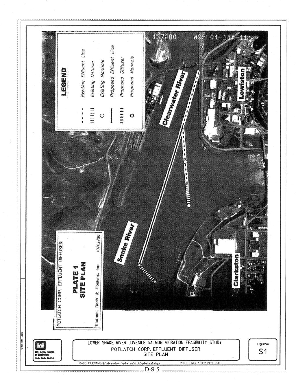
1 Annex S Potlatch Corporation Effluent Diffuser Modification Plan Figure S1 Figure S2 Site Plan Effluent Pipeline Trench H:\WP\1346\Appendices\FEIS\D - Drawdown\CamRdy\App_D.doc
2 Annex S: Potlatch Corporation Effluent Diffuser Modification Plan S.1 General The concepts and costs for this water intake modification plan derive from a separate report prepared for the Corps by Thomas, Dean & Hoskins, Inc., titled Snake River Drawdown Feasibility Study for: Plant Effluent Diffuser Potlatch Corporation (TDH, 1998b). Modifications describe here are not considered as part of the project implementation costs. The plan and costs were developed for economic evaluations of local, regional and national impacts. The Lewiston, Idaho, division of Potlatch Corporation imports wood and wood byproducts (wood chips) and manufactures and supplies wood, paper, and consumer products to the Northwest. Treated effluent from the plant is conveyed to its discharge location through a 1,219-millimeter (48-inch) effluent pipeline west of the plant. The effluent pipeline enters the Clearwater River at approximately river kilometer 0.85 (river mile 0.53). From its entrance into the Clearwater River, the 1,219- millimeter (48-inch) effluent line then runs west to the confluence with the Snake River, where a 122-meter- (400-foot-) long diffuser section is located. The effluent diffuser consists of a 1,219- millimeter (48-inch) pipeline fitted with 102- millimeter (4-inch) nozzles located at the top of the pipe. The 102- millimeter (4-inch) nozzles are connected to 76- millimeter (3-inch) polyethylene pipes that discharge effluent into the stream. Diffusers are spaced 1.5 meters (5 feet) center to center. During the 1992 experimental drawdown (Corps, 1992), the top portion of the polyethylene diffusers were exposed. It is clear that a proposed drawdown of the four lower Snake River reservoirs would mandate the relocation of the effluent diffuser to a deeper area within the river. According to Potlatch, the existing effluent pipeline and diffuser system is operating adequately. An underwater inspection was conducted a year prior to this study and revealed that only minor improvements were required to replace a few polyethylene diffusers. Improvements outlined in this report would not be required under current plant operation, but would be required if the proposed drawdown occurs. Currently, there is much debate on the issue of temperature of the river water and the consequent water quality. There has been discussion on whether the Potlatch effluent affects the temperature regime and whether water treatment to control effluent temperature is necessary. The added effects of drawdown provide further concerns. This annex only address a replacement system to relocate the existing effluent diffuser. Treatment systems for the water are beyond the scope of this report but future circumstances may require water treatment systems to be added to this modification plan. S.2 Standards S.2.1 Relevant Codes and Standards Effluent discharge is regulated by the U.S. Environmental Protection Agency under the regulations stipulated in Title 40, Chapter I, Subchapter D - Water Programs of the Code of Federal Regulations. D-S-1
3 Since several endangered species within the Snake and Clearwater rivers might be affected by construction operations, all work within the rivers is also regulated by the National Marine Fisheries Service as stipulated in Title 50 of the Code of Federal Regulations. S.2.2 Design Criteria 1. Plant Effluent Requirements: Average daily discharge: 160 to 200 million liters (35 to 45 million gallons) per day (source: Potlatch) Peak flow: 2.0 m 3 /s (71.3 cfs) (source: Potlatch) 2. Postdrawdown Stream Characteristics: Minimum stream bottom elevation (at proposed diffuser location): 212 meters (694 feet) (source: Corps) Low water elevation (at 566 m 3 /s [20,000 cfs]): 216 meters (709 feet) (source: Corps) 100-year high water elevation (at 9,062 m 3 /s [320,000 cfs]): 220 meters (723 feet) (source: Corps) S.3 Diffuser Modifications S.3.1 Options Because there are many unknowns concerning the effects of drawdown, such as river high-water elevation and velocity and stream bottom elevations, the options included in this report were selected based on a number of assumptions as well as engineering judgment. The existing effluent pipeline and diffuser is shown in Figure S1. Based on streambed profiles supplied by the Corps and streambed contours provided by Potlatch, it appears that the existing diffuser is located on a shelf within the Snake River. Assuming the stream bottom profiles are accurate, the stream bottom is significantly deeper (by about 0.9 meter [3 feet]) just 366 meters (1200 feet) downstream of the existing effluent diffuser location. The proposed location for the new effluent diffuser is within this deeper pool along the Snake River. Because the existing facility is performing adequately, the existing effluent pipeline up to the first angle point would be used in this modification plan. The new diffuser would be designed with the same length and geometry as the existing diffuser, but would be installed perpendicular to the river flow at its new location. Future design should include an evaluation of sediment erosion to determine the stable depth at which to set the pipe. This is to prevent erosion of the foundation under the pipeline or adverse hydraulic conditions in the river. Manholes would be constructed at pipeline angles and at the terminus of the new diffuser. The manhole at the angle point consists of 1,219-millimeter (48-inch) flange fittings with a short section of 1,219-millimeter (48-inch) vertical pipe. The end of the vertical pipe would be fitted with a blind flange. The terminus manhole would consist of 1,219-millimeter (48-inch) flange fitting with a 914-millimeter (36-inch) vertical pipe and a special diffuser connection. D-S-2
4 The effective operation of the diffuser requires that it be continually submerged. This requirement forces the installation of the new pipeline and diffusers to be completed prior to initiating drawdown. Sediment deposition in this region has resulted in a significant accumulation of sediment that must be excavated to install the diffuser pipeline. Most of this accumulated sediment on the river bed is predicted to be eroded away during the first year drawdown occurs. See Figure S2 for a cross section of the installed effluent diffuser. Since river flows are not affected by drawdown, the study team assumed that no change in the dilution of the effluent would occur by postdrawdown stream flow. If it is determined that additional treatment would be required, the estimated construction costs noted in this report would not adequately cover the additional costs for this treatment. Changes to the effluent diffuser to prepare for drawdown conditions will require consultation with various regulatory agencies with respect to effects to endangered and threatened species. Issues regarding mixing of effluent with river water may require additional systemic modifications to be made to guarantee compliance with permit conditions. Such modifications could result in additional capital costs ranging up to $50 million should a complete wastewater treatment facility be necessary. S.3.2 Construction Methods There are two primary construction methods used for this type of in-water construction. A common method is to surround the construction area with a sheetpile cofferdam system that allows the construction area to be dewatered. The installation of the pipeline section and the diffuser section can take place in relatively dry conditions. After completion of the installation, the sheetpile is removed. Underwater construction would include use of a barge with a clamshell excavator to excavate the trench. The upstream part of the trench would have cofferdams installed to prevent trench wall caving. There are two options available for installing the pipe underwater. One option is to preconstruct up to three 12-meter (40-foot) lengths of pipe on board a barge, cap the pipe, float it to the installation location, sink it, uncap it, and connect it underwater to the existing pipe. Another option is to preconstruct five or six lengths of 12-meter (40-foot) pipe on shore, then cap them and float them out to the installation location. The pipe is then sunk, uncapped, and connected to the existing pipe. This procedure would use four divers, two diver tenders, and a crew to support the excavation and dry land connections of pipe. It would be typically less expensive to work off the shore connecting the pipe rather than on the barge, if possible. The cost for these procedures is comparable to using cofferdams to provide for all dry construction. The study team selected cofferdam construction rather than underwater construction for installation of the pipeline sections. The primary reason was that underwater construction created turbidity in the water caused by excavation and backfill of the trench. The construction method for modifying the Potlatch plant effluent diffuser system is summarized as follows: 1. Cofferdams Cofferdams would be constructed in two phases. The first phase would consist of cofferdams around the effluent pipeline between the new diffuser and the connection to the existing effluent pipeline. Once the pipeline installation within this area is complete, the cofferdams would be removed and cofferdams would be constructed around the proposed effluent diffuser. For the purposes of this study, sheetpile cofferdams are proposed. D-S-3
5 2. Trench Excavation Trenches would be constructed using open-cut trench methods. Assuming 1,219-millimeter (48- inch) pipelines would be installed, the minimum trench width would be 2 meters (6 feet). This study team assumed that the pipe would be installed above 305 millimeters (12 inches) of pipe bedding and that 914 millimeters (36 inches) of cover would be required above the pipe. Therefore, the total trench depth would be 2.4 m (8 feet). 3. Pipeline Installation Effluent and diffuser pipelines would be 1,219-millimeter (48-inch) ductile iron. The total length of solid effluent pipe between the existing effluent pipeline and proposed diffuser is 914 m (3,000 feet). An additional 122 m (400 feet) of perforated ductile iron pipe would be required for the diffuser. Perforations would be 102-millimeter (4-inch) drilled holes, threaded to accept the 102-millimeter (4-inch) ductile iron diffuser pipes. Then 76-millimeter (3-inch) polyethylene diffusers would be attached to the end of the ductile iron diffuser segments. Approximately 457 millimeters (18 inches) of polyethylene diffuser would be exposed above the stream bottom. 4. Concrete Fill of Abandoned Pipe and Diffuser A high slump concrete would be pumped into the abandoned pipe and diffuser. Existing, exposed diffuser pipes would be cutoff at ground level and removed from the site. 5. Trench Backfill Trenches would be backfilled with granular borrow from the top of the pipe bedding to the existing ground surface. Sources for the backfill material are available within the local area, minimizing long haul charges. 6. Streambed Armor The existing stream bottom over the new pipeline would be lined with heavy riprap to preclude scour. The study team estimated that the material size would be between 457 millimeters (18 inches) and 914 millimeters (36 inches) in size (D 50 = 610 millimeters [24 inches]). Riprap would be placed a distance of 30 m (100 feet) upstream and downstream of each pipeline. The team assumed that riprap would be hauled from a nearby quarry, and that some haul costs would be incurred. 7. Remove Cofferdams Once the diffuser installation is tested and accepted, the sheetpile cofferdams would be removed, and the system placed in service. S.3.3 Construction Materials 1. Pipe: 1,067-millimeter (42-inch) outside diameter (OD), class 51 ductile iron (wall thickness = 13.5 millimeters [0.53 inches]) 2. Pipe fittings: mechanical joints 3. Pipe coating: asphaltic lining S.4 Schedule Work would need to be done before drawdown. The ideal construction window would occur between October and November when stream flows are minimal. Working during minimized stream flows would minimize construction costs. D-S-4
6
7