Emergency Action Plan for Coal Combustion Residuals Unit
|
|
|
- Lorraine Gaines
- 5 years ago
- Views:
Transcription


1 Emergency Action Plan for Coal Combustion Residuals Unit J. R. Whiting Facility Prepared for Consumers Energy Company April 2017 Barr Engineering Co Boardwalk Street, Suite 100 Ann Arbor, MI 48108
2 Emergency Action Plan for Coal Combustion Residuals Unit at J. R. Whiting Facility April 2017 Contents Certification... ii 1.0 Introduction CCR Unit Safety Emergency Events or Circumstances Which Represent a Safety Emergency Detection Procedures Delineation of the Downstream Affected Area Responsible Persons, Responsibilities, and Annual Exercise Meeting Revisions References... 9 List of Figures Figure 1 Figure 2 Figure 3 Figure 4 Figure 5 Site Plan Approximate Affected Area Due to Failure of West Dike Approximate Affected Area Due to Failure of South Dike Approximate Affected Area Due to Failure of East Dike Emergency Action Plan Notification Procedure \\barr.com\projects\ann Arbor\22 MI\58\ Consumers JRW CCR EAP\WorkFiles\EAP\JRW CCR EAP docx i
 and in accordance with standard engineering practice, including consideration of applicable industry standards.")
3 Certification I hereby certify that this emergency action plan complies with the provisions of Title 40 of the Code of Federal Regulations Section (40CFR ) and in accordance with standard engineering practice, including consideration of applicable industry standards. Further, I hereby certify this plan was prepared by me or under my direct supervision and that I am a duly licensed Professional Engineer under the laws of the State of Michigan. Bethany Kelly PE #: April 13, 2017 Date ii
4 Acronyms Acronym CEC CCR CFR EAP EPA HPCR ICS JRW Description Consumers Energy Company Coal Combustion Residuals Code of Federal Regulations Emergency Action Plan Environmental Protection Agency Hazard Potential Classification Report Incident Command System J. R. Whiting Facility iii
5 1.0 Introduction Consumers Energy Company s (CEC) J. R. Whiting (JRW) facility stores coal combustion residuals (CCR) in surface impoundments, which are classified as significant hazard potential units in accordance with United States Environmental Protection Agency s (EPA) 40 CFR Part 257 (specifically 40CFR (a)(2). Therefore, pursuant to the 40CFR (a)(3)(i)), this facility must prepare and maintain a written Emergency Action Plan (EAP). The purpose of the EAP is to define emergencies related to CCR surface impoundments, define responsible persons, and define notification procedures in the event of an emergency. The EAP must be completed and placed in the facility s operating record no later than April 17, CFR (a)(3)(i)) requires that the owner or operator of the CCR Unit (EPA 2015): A. Define the events or circumstances involving the CCR unit that represent a safety emergency, along with a description of the procedures that will be followed to detect a safety emergency in a timely manner; B. Define responsible persons, their respective responsibilities, and notification procedures in the event of a safety emergency involving the CCR unit; C. Provide contact information of emergency responders; D. Include a map which delineates the downstream area which would be affected in the event of a CCR unit failure and a physical description of the CCR unit; and E. Include provisions for an annual face-to-face meeting or exercise between representatives of the owner or operator of the CCR unit and the local emergency responders. The JRW facility is located in Erie, Michigan (shown on Figure 1). JRW s CCR surface impoundment (CCR unit), Pond 1&2, has been classified as a significant hazard potential CCR surface impoundment (Mannik Smith Group, 2016). The EAP provides CEC with a pre-planned and organized method to identify and implement a response to a safety emergency related to the CCR unit. The impoundments are bounded on the west by the west forebay, on the south by the facility s formerly used cooling water discharge channel, and on the east by a public beach on the shore of Lake Erie. The generation facility is not in operation and no longer discharges water or CCR material to the impoundments. Only rain which falls on the impoundments and potential, though unlikely, precipitation overflow from the nearby treatment ponds contribute additional water to the impoundments. 1.1 CCR Unit The CCR unit is bounded by a perimeter dike and is separated into two ponds by an internal dike. The perimeter dikes were constructed of CCR material and clay excavated during construction of the unit. The unit was originally constructed as a single pond prior to plant operation in 1952 and was used to store fly ash. In 1964, the pond was reconstructed into two ponds to assist in clarifying water from the sluiced bottom ash (Consumers, 2016). The unit was completed as part of the initial construction of the facility. When the generating facility was in operation, CCR and water was sluiced to the bottom ash pond. Water gravity flowed from Pond 2 1
6 to Pond 1 via a submerged pipe in the internal dike before discharging from Pond 1 to the west forebay at Outfall 001b (AECOM, 2009). Since the plant is no longer operating, Outfall 001b has been grouted in place to prevent discharge from the pond. Key features and hydraulic connections of the waterbodies adjacent to the CCR unit are shown on Figure 1. As depicted, the west forebay is connected to the intake channel (Maumee Bay) through a concrete structure beneath the causeway. The discharge channel is connected to Lake Erie via culverts at the east end of the channel. Formerly, the west end of the discharge channel was connected to the intake channel via a recirculating gate structure, but this has been permanently closed and filled with concrete. 2
7 2.0 Safety Emergency For purposes of this EAP, a safety emergency would occur if the subject CCR unit failed or if failure were imminent. While the magnitude or severity of such a safety emergency might vary, the EAP was prepared with conservative assumptions that a catastrophic failure of the CCR unit occurred. Additional actions after the initial response (cleanup, investigation, repairs, etc.) would be geared toward the actual conditions of the emergency and are, therefore, not prescribed in this EAP. 2.1 Events or Circumstances Which Represent a Safety Emergency A safety emergency occurs in the event of failure of the CCR unit, or if observed conditions represent imminent failure of the CCR unit as determined by a professional engineer in the GE&S Systems Engineering Infrastructure group (an internal CEC group of subject matter experts) in consultation with Qualified Personnel at the facility (Qualified Person as defined in 40CFR : a person trained to recognize specific appearances of structural weakness and other conditions which are disrupting or have the potential to disrupt the operation or safety of the CCR unit by visual observation). Imminent failure will be determined based on knowledge of the CCR unit construction and the failure modes evaluated in the Potential Failure Mode Analysis performed for the facility (AECOM, 2009). Potential failure modes include a physical dike failure (i.e., uncontrolled seepage causing internal dike erosion and dike breach) and/or overtopping and erosion of the dike (due to a significant storm event). A final, although unlikely, potential failure mode would be failure induced by uncontrolled earthwork such as excavation at the toe of slope and/or placement of excess load on side slopes or slope crests, such as by heavy equipment activity or a seismic event induced movement causing instability of the dike; any of which may in some circumstances initiate slope failure. 2.2 Detection Procedures The CCR units are periodically inspected for structural and operational conditions by a Qualified Person in adherence with 40CFR (a)(1) and (a)(1). Weekly inspections are completed to monitor and document the physical condition of the CCR units. In these inspections, the Qualified Person conducts a visual evaluation for conditions such as vegetation, beaching, bulging, depressions, cracking, erosion rilling and gullies, seepage, sloughing and sliding, or unnatural settlement (CEC, 2015). Observations are reviewed by an employee of the site s Environmental & Technical Support department. If conditions of potential concern are observed they are promptly reported, after which notification and response procedures may be enacted (see Section 3.0). Annual inspections are completed by a qualified Professional Engineer (CEC, 2015). This annual inspection also includes a review of available information, including weekly inspection reports, to understand trends which may be apparent based on changes documented over time. Periodic assessments are also completed as required by the CCR rule. Beyond the visual indicators that are reviewed in weekly inspections, specific items inspected for include, but may not be limited to: 3
8 New and/or uncontrolled slope erosion Indicators of potential slope movement such as: o o o changes in dike alignment changes in dike crest elevation cracks in dike surface Whirlpool within pond Turbid discharge water CCR unit pond level and freeboard Indications of seepage through dikes such as: o o soft/saturated toe of slope mid-slope water discharge Uncommon variation in vegetation type and density Members of the public may report a condition or situation indicative of an emergency event to emergency dispatch (911); see Section 3.0. Currently, the CCR units do not have, nor do they require, instrumentation. 2.3 Delineation of the Downstream Affected Area According to the Hazard Potential Classification Report (HPCR) for Pond 1&2 (Mannik Smith Group, 2016), potential dike failures may occur along the east, west, and south slopes of the impoundment dike. The HPCR states that a breach of the impoundment dike would result in a discharge of CCR material and water to the west forebay and then to Maumee Bay, causing an anticipated rise in the water level of the west forebay and discharge into Maumee Bay. The HPCR therefore categorized the impoundments as significant hazards because no probable loss of human life is expected, however, environmental damage may result which would not be limited to CEC property. In development of the EAP for JRW pursuant to 40CFR , Barr created Figures 2, 3, and 4 to approximate the area which would be affected by a catastrophic discharge of CCR material and water from the impoundments to the potential receiving waters of the breaches. Based on a review of the surrounding topography, a breach of the west dike would presumably discharge to the west forebay (Figure 2), a breach of the south dike would discharge to the discharge channel then to Lake Erie (Figure 3), and a breach of the east dike would discharge to Lake Erie (Figure 4). The affected areas presented on these figures were estimated based on the volume of stored CCR material and water which could potentially be discharged during an emergency event using the conservative breach scenarios identified in the HPCR. The west dike breach scenario assumes that a breach would occur at the point of the former outfall adjacent to the west forebay. 4
9 According to the HPCR, a conservative breach scenario would assume the volume of water and CCR material resulting from a 1,000 year storm event. Per the HPCR, the volume of the two ponds would be approximately 150 acre feet. A conservative scenario would presume that the entirety of this volume would be discharged at once during an emergency event. Under this assumption, an affected area might include 150 acres of the area adjacent to a dam breach (assuming an inundation of 1 foot). This is a conservative assumption since a break resulting in the instantaneous and simultaneous discharge of the entire maximum storage capacity from both ponds would be unlikely. Using the conservative inundation area and topographic data for the adjacent areas (NOAA OCM, 2012) the approximate affected area shown on Figures 2, 3, and 4 depicts the water and shoreline which would be affected by the 1-foot inundation inclusive of the 150-acre area. The edges and general shape of this area are approximate. 5
10 3.0 Responsible Persons, Responsibilities, and Notification Procedures In adherence with 40CFR (a)(3)(B), Figure 5 outlines the approach to responding to a CCR unit safety emergency. Responsible persons, their responsibilities, and the notification order are summarized on Figure 5 to provide a quick-reference document during implementation of the EAP. In the event that a long-term response action is necessary, the Short-term On-Scene Commander will activate needed positions within CEC s Incident Command System (ICS) based upon the needs of the incident. The ICS and related programs are outside the context of this plan and the notification procedures defined herein. Pursuant to 40CFR (a)(3)(C), Figure 5 also shows emergency responders, including their contact information, and who will be contacted in the event of a safety emergency. 6
11 4.0 Annual Exercise Meeting An annual meeting will be coordinated by Environmental & Technical Support department personnel and will include CEC representatives and local emergency responders. The CEC representatives and emergency responders included on Figure 5 will be invited to participate. 7
12 5.0 Revisions CEC has a program to periodically review and amend emergency planning documents. The EAP will be included in this program and reviewed, at a minimum, every five years. The current EAP, i.e. the reviewed or revised EAP, will be placed in the facility s operating record as required by 40CFR (f)(6). 8
13 6.0 References AECOM, Potential Failure Mode Analysis (PFMA) Report for J.R. Whiting Generating Facility. AECOM Project No December 7, Consumers Energy Company, JR Whiting History of Construction Ponds 1&2. October 17, EPA (Environmental Protection Agency), Disposal of Coal Combustion Residuals from Electric Utilities; Final Rule. 40 CFR Part 257. Effective Date October 19, Mannik Smith Group, J. R. Whiting Generating Facility Ponds 1 and 2 Hazard Potential Classification Report. October, NOAA OCM, NOAA Office for Coastal Management (OCM) USACE Great Lakes Topobathy Lidar: Lake Erie (MI, OH, PA, NY). Released,
14 Figures


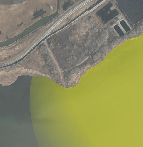
15 Barr Footer: ArcGIS 10.4, :47 File: I:\Projects\22\58\1014\Maps\Reports\Figure1_SitePlan_JRWplant.mxd User: Mac2 Erie Road Erie, MI Monroe County Former Combined Outfall 001b (Grouted) Po nd 1!H West Forebay Pond 2 Outfall 001a Discharge C hannel!h Intake Channel Treatment Ponds Lake Erie Maumee Bay Hydraulic Connection (Locations Approximate)!;N Feet SITE PLAN JR Whiting Generating Plant 4525 E. Erie Road Erie, Michigan Consumers Energy Company FIGURE 1 Aerial Source: 2015 SEMCOG


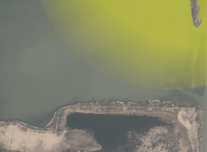


16 Barr Footer: ArcGIS 10.4, :48 File: I:\Projects\22\58\1014\Maps\Reports\Figure2_SitePlan_JRWplant_FailureScenario1.mxd User: Mac2 Erie Road Erie, MI Monroe County Failure of West Dike!H Pond 1 West Forebay Pond 2 Disc harge Channel Treatment Ponds Int ake Channel Maumee Bay Affected Area: Potentially Impacted by CCR or Minor (<1 ) Water Level Rise!H Failure Location!;N Feet APPROXIMATE AFFECTED AREA DUE TO FAILURE OF WEST DIKE JR Whiting Generating Plant Consumers Energy Company FIGURE 2 Aerial Source: 2015 SEMCOG


 Water Level Rise!")
17 Barr Footer: ArcGIS 10.4, :49 File: I:\Projects\22\58\1014\Maps\Reports\Figure3_SitePlan_JRWplant_FailureScenario2.mxd User: Mac2 Erie, MI Monroe County Erie Road Pond 1 West Forebay Pond 2!H Disc harge Channel Failure of South Dike Lake Erie Treatment Ponds Intake Channel Maumee Bay Affected Area: Potentially Impacted by CCR or Minor (<1 ) Water Level Rise!H Failure Location!;N Feet APPROXIMATE AFFECTED AREA DUE TO FAILURE OF SOUTH DIKE JR Whiting Generating Plant Consumers Energy Company FIGURE 3 Aerial Source: 2015 SEMCOG


 Water")
18 Barr Footer: ArcGIS 10.4, :49 File: I:\Projects\22\58\1014\Maps\Reports\Figure4_SitePlan_JRWplant_FailureScenario3.mxd User: Mac2 Erie, MI Monroe County Erie Road Pond 1!H Fai lure of Eas t Dike West Forebay Pond 2 Disc harge Channel Lake Erie Treatment Ponds Intake Channel Maumee Bay Affected Area: Potentially Impacted by CCR or Minor (<1 ) Water Level Rise!H Failure Location!;N Feet APPROXIMATE AFFECTED AREA DUE TO FAILURE OF EAST DIKE JR Whiting Generating Plant Consumers Energy Company FIGURE 4 Aerial Source: 2015 SEMCOG
 DEK On Call Shift Supervisor Determines if failure has already occurred (989.891.")
19 Note: DE Karn (DEK) personnel will provide assistance with emergency notification procedures Public Observation of potential emergency condition Plant Personnel Observes emergency condition Emergency Dispatch (911) DEK On Call Shift Supervisor Determines if failure has already occurred ( ) DEK Plant Control Room Operator Receives notification and engages plant environmental manager ( ) Has Failure Occurred? No Yes GE&S Systems Engineering - Infrastructure Technical expert makes imminent failure determination in consultation with qualified personnel at the facility ( ) DEK On Call Shift Supervisor or their Designee ( ) Makes or coordinates notification calls to external (first priority) and internal contacts (in the numbered, priority order, as shown). The caller should collect the following information and provide it to the notified parties: -The discharge is coal combustion residual material from the facility s coal ash surface impoundment (provide CCR unit identification, if known) -Location of the breach and magnitude of the discharge (if known) -If the discharge is ongoing or if the potential for additional discharged material is unlikely -The affected or anticipated to be affected water bodies -If the discharge has affected (or may affect) the public beach Internal Notifications Is Failure Imminent? No Maintenance or Repair Procedures No emergency response necessary Yes 6. Short-term On-Scene Commander DEK Shift Supervisor who is the leader of Emergency Response Actions and initiates Incident Command System (ICS) if necessary ( ) 7. DEK Environmental & Technical Support Provides technical support and makes additional environmental contacts as appropriate ( ) 8. Environmental Services Coordination of cleanup contractors and disposal ( ) 1. Emergency Dispatch (911) Emergency Responder Notifications 2. National Response Center (NRC) ( ) 3. Michigan Pollution Emergency Alert System (PEAS) ( ) 9. DEK Environmental Lead Provides environmental technical assistance and assists with any potential environmental restoration ( ) 10. Site Security Lead Coordinates site security with corporate security ( ) 11. Public Affairs Coordinates communications to public ( ) 4. MDEQ Southeast Michigan District Office NPDES Permit MI ( ) 5. US EPA Region V Spill Phone ( ) 6. Monroe County Alert Notification System ( during workday, after-hours notification via 911-dispatch) Figure 5 EMERGENCY ACTION PLAN NOTIFICATION PROCEDURE Ponds 1 & 2 J. R. Whiting Facility Erie, MI