The Basics. Reverse Osmosis is a process that is used to remove. Front Side 1. Controller
|
|
|
- Anna Greene
- 5 years ago
- Views:
Transcription
1

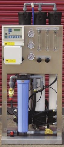
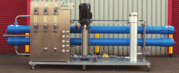
2 The Basics Front Side 1. Controller 2. Transformer/relay 3. Inlet 3 /4 BSPM 4. Drain Outlet 3 /4 BSPM 5. GAC Filter 6. Pressure control 7. Low pressure gauge 8. Pump pressure gauge 9. Back pressure gauge 10. Inlet solenoid 11. Recirculation flow control 12. Flush flow control 13. Flush solenoid 14. Conductivity probe 15. Permeate flow meter 16. Concentrate flow meter 17. Permeate outlet 1 /2 Compact Membrane 19. Low pressure switch 20. Membrane connections 21. Pump motor 22. Pump 23. High pressure switch 24. Recirculation flow meter Reverse Osmosis is a process that is used to remove a wide range of salts to give water of a high purity - Osmosis is a natural process involving fluid flow across a semi-permeable membrane barrier. It is the process by which nutrients feed the cells in our bodies and how water gets to the leaves at the top of trees. If you separate a solution of salts from pure water using a basic thin semi-permeable membrane like a sausage skin, the pure water passes through the membrane and tries to dilute the salt solution. If the salt solution is connected to a vertical pipe then the progressively diluted solution will fill the pipe until the 'osmotic pressure' drawing the pure water though the membrane is the same as the head pressure of the diluted solution. This process can be reversed - hence 'Reverse Osmosis' - by applying a higher pressure to the salt solution. Pure water will then pass the other way through the membrane in a process that is easy to visualise as 'filtration' where the filter will only let through the small water molecules and retain almost all of the other molecules. This means that water containing a high level of natural salts can be purified without the need for chemical regenerants such as the acid and caustic used in demin plants. Reverse Osmosis is therefore considered a much safer route of producing pure water for many commercial and industrial applications, and additionally the plant does not need to be taken out of service for regeneration as a Demin plant does. Rejection rates of salts from water is generally in the region of % dependent upon the membrane type used and the raw water feed quality. RO systems can be designed to utilise the wide range of membranes available, which will give different permeate water qualities. Standard designed RO's are manufactured utilising the Low Energy Membranes which will give a permeate water quality of approx. 10 microsiemens from an input water of between microsiemens. Left: RoPro 8-203K 10m3/hr output with CIP Front Cover: Compact 6000 (Top) RoPro m3/hr Basic Unit (Bottom)
 is collected and passed to service.")

3 RO System Management Reverse Osmosis systems, in their basic form, consist of a pressure pump, housing and the membrane. Water is forced into the housing under pressure and the pure water (or permeate) is collected and passed to service. Reject water (or concentrate) is collected from another outlet and routed to drain, with a portion of the concentrated water recycled back to the inlet of the pump. This means that the portion of water sent to drain is kept to a minimum allowing a recovery ratio of approx. 75% to be achieved without significant fouling of the membrane. The recirculation allows a higher flow of water through the pump reducing the load on its bearings and keeping the pump running cooler. The recirculation on all units is adjustable. The controller used on the RO system constantly monitors the quality of the permeate water and is also linked with safety controls on the system, to ensure the unit cuts out on low & high pressure, high & low conductivity and full permeate tank signal. It will also run various pre & post flush cycles to maximise the life time of the membrane. The constant monitoring is automatic and the programming is all preset to ensure protection of the system at all times and to maximise the quality of the pure water. RO plants must be supplied with softened, de-chlorinated or de-chlorinated anti scalent dosed water. A duplex softener is recommended for continuous operation. Utilising softened water for the feed to the RO will reduce the scaling potential on the membrane and therefore lengthen its working life. De-chlorination of the feed will reduce oxidation damage to the surface of the membrane. High output reverse osmosis plant offers considerable advantages over traditional deionisation systems, with no acid/caustic consumables nor problems with COSHH compliance. If softened service water is needed elsewhere on the same installation site, concentrate water can be returned to a softened water holding tank, eliminating water wastage. Nominal Element Performance - ESPA Element Type ESPA1 ESPA2 ESPA3 ESPA4 ESPA ESPA ESPA ESPA ESPA Minimum Salt Rejection, % (avg.) (avg.) Permeate Flow, GPD 12,000 9,000 14,000 12,000 4,000 3,000 4,500 2,500 (m 3 /d) Test parameters C, 150psi applied pressure, pH range, 15% recovery B Series RO

4 Specifying and Sizing RO Dimensions Width mm Depth mm Height mm RO B Series RO Compact RO Pro4 Range RO Pro 8-75 & RO Pro 8-50 & RO RO Pro & RO Pro RO Pro 8-53K to 8-103K RO Pro 8-153K to 8-203K The 8-75 to systems can be built on a smaller foot print at an additional cost. The size of the RO and choice of membrane will be determined by the permeate quantity required, feed water salinity and permeate quality expected. Low energy membranes allow the units to run at pressures around psi, and as such the pressure booster pumps required to generate the pure water are smaller, and the power consumption is reduced significantly. These membranes will produce water quality of approx. 10 microsiemens from an input water of between microsiemens. If higher permeate quality is required a different range of membranes with higher pressure pumps can be used. RO units are normally built and used as single units producing the quantity required during the working day. If circumstances demand, the RO units can be duplexed with a central control panel being used to allow manual or automatic switching of the RO plant in service, and will also allow the units to run in parallel when the demand for water is higher, thus doubling the permeate production. Also for very high purity waters the RO can be manufactured in "double pass mode" - This means the permeate water from the first unit is fed as raw water into the second pass of the RO - This already high quality water will then be improved and a very pure water is produced, typically less than 1 microsiemen. When sizing the pre-treatment system the quantity of water available on the raw water feed side needs to be checked carefully as the RO system needs a higher feed flow than it s permeate output, as the recovery of the units is approx. 75% for the pure water. The 25% concentrate that is rejected by the RO can be used for any application where soft water is required such as wash water, grey water for toilet flushing or in some cases cooling tower make-up. The use of this water minimises any waste from the feed supply. RoPro 4-38
5 RO Plant Size and Technical Specification B SERIES / COMPACT B/C1000 B/C2000 B/C4000 C6000 C8000 Output litres/hour ,200 Input litres/hour - 75% Recovery ,200 1,600 Membrane (ESPA-1) x x x 4040 Pump Power KW (3 phase) RO-PRO MODEL Output litres/hour 1,600 1,900 2,200 Input litres/hour - 75% Recovery 2,150 2,550 2,950 Membranes Hydranautics ESPA No Membranes Pump Pressure (bar) Pump Power KW RO-PRO MODEL 8-50 & 8-53K 8-75 & 8-73K & 8-103K & 8-153K & 8-203K Output litres/hour 2,500 3,750 5,000 7,500 10,000 12,500 15,000 20,000 Input litres/hour - 75% Recovery 3,300 5,000 6,667 10,000 13,333 16,900 20,000 26,667 Membranes Hydranautics ESPA No Membranes Pump Pressure (bar) Pump Power KW All flow rates quoted are on softened towns mains ambient temperature and running at 75% recovery - Actual flow rates will depend on a number of factors including feedwater temperature, quality, feed pressure, pre-treatment and age of RO plant C1000 to C6000 systems are built with 230V 50Hz single-phase pumps as standard v 50Hz three phase pumps are optional. All other systems are built with 400V 50Hz three phase pumps.
6 Softener Size (litres of resin) Flow Rate Information Capacity at 300ppm Total Hardness (m 3 ) Service Flow m 3 /hour Valve Specifications Fleck /4 Connections: 1 BSP inlet & outlet. 1 /2 hose barb drain Fleck Connections: 1 BSP inlet & outlet. 1 /2 hose barb drain Fleck 9500 Connections: 1.5 BSP inlet & outlet. 1/2 hose barb drain Fleck 2900 Connections: 2 BSP inlet & outlet. 1 BSP drain RO Pre-Treatment Systems Softener and carbon Filter sizing - Softeners are all based on Duplex valves and capacities quoted are per vessel. Please call if you require further clarification or assistance on the RO plant pre-treatment sizing. Duplex Water Softeners Maximum Flow Rated at 4.00m 3 per hour Maximum Flow Rated at 4.70m 3 per hour Maximum Flow Rated at 9.60m 3 per hour Maximum Flow Rated at 23.00m 3 per hour PLEASE NOTE: When sizing softeners, please ensure that the valve being used is able to handle the flow rate required by the system. Activated Carbon Filters Stock Code FA1054/EN FA1248/EN FA1354/EN FA1465/WC FA1665/WC FA1865/WC FA2160/WC FA2469/WC FA3072/WC FA3672 FA4278 FA4882 Flow Rate Information m 3 /hour BW Rate m 3 /hour Valve F2510 F2510 F2510 F2510 F2510 F2750 F2750 F2750 F2850 F3150 F3150 F3510 Connections Inlet/Outlet 1 BSP 1 BSP 1 BSP 1 BSP 1 BSP 1 BSP 1 BSP 1 BSP 1.5 BSP 2 BSP 2 BSP 2 BSP Flow rates advised are for de-chlorination of the feed water only. If organic reduction is required please call for sizing assistance. The Right Product...At the Right Price...At the Right Time