Attachment N o F Control & Monitoring
|
|
|
- Ethelbert O’Neal’
- 5 years ago
- Views:
Transcription
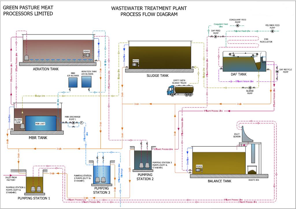
1 Attachment N o F Control & Monitoring Attachment F1: Treatment, Abatement and Control Systems Air There is no treatment or abatement systems required for the minor air emission points or the potential air emission point as their individual and combined impact is negligible. Effluent The fat traps on the drains in the slaughter house and boning hall provides an important abatement to reduce the entrainment of solids in waste water and consequently reduced COD, BOD and TSS loadings in the waste water. It is proposed that Green Pasture Meat Processors Ltd. will construct a biological waste water treatment plant (WWTP) on site within 9 months of the issue of the IE licence. The proposed WWTP will treat process effluent arising from the site. The WWTP will be fully BAT and BREF compliant in regard wastewater management within 16 months from the EPA s final approval. The treated effluent discharge will be gravity fed to the Mill Stream which is situated c.0.6km northeast of the site (SW4). Discharge will comply with the following proposed emission limit values: Parameter Units Proposed Discharge ELV s BAT Slaughtering Sector BREF Slaughterhouses & Animal By-products Flow m 3 60/day - - ph ph units Toxicity units TU BOD mg/l COD mg/l Suspended Solids mg/l Total Ammonia (as N) mg/l Total Nitrogen mg/l Total Phosphorus (as mg/l P) Orthophosphate mg/l Oils, fats & grease mg/l Table 1 Proposed ELV s for final treated effluent A detailed description and schematic drawings and maps of the proposed WWTP are outlined in the following sections. Proposed WWTP Process Description of WWTP Process water from the production plant will be collected into a common drain, directed into two on site collection chambers and then forwarded to the new treatment plant. Effluent from the plant will be treated as follows: (i) (ii) An inlet screen to remove solids greater than 2mm; A 24/7 balance tank;
2 (iii) (iv) (v) (vi) A dissolved air flotation (DAF) system to remove fats oil and grease; An aeration system to break down the organic loading; A MBR to clarify the water prior to discharge; and A sludge holding tank. The plant is designed to process from 50-75m 3 of effluent per day and is adjustable to meet the present and future requirements of the site. It is estimated that c.7,500m 3 of process wastewater will be generated at the site annually. Design Loadings of WWTP From proposed WWTP to Mill Stream. Parameters Inlet Outlet Flow (m 3 ) BOD (mg/l) COD (mg/l) 6, SS (mg/l) Fats oil & Grease (mg/l) Phosphates (mg/l) 20 2 Ammonia (mg/l) Total Nitrogen (mg/l) PH (ph units) to 9.0 Specifications of the WWTP ITEM Pumping station for balance tank The existing concrete tank recently installed on site will be as a pumping station, the tank measures: Length 12.0 m 3.0 m Width 3.0m Free Board 0.5m Volume 100 m 3 The tank is free standing and is a built in-situ pre-stressed concrete tank complete with connection point flanges. ITEM Process transfer pumps for balance tank One set of submersible pumps (one duty/one standby) driven by 1.5 kw, 4 pole, 380 volt IP 68 standard submersible motors will be installed and located in the main pumping station. Pump capacity 10.0 m³/h Total head 10m ITEM Inlet screen Inclined screen - Frame and material: SS Spacing: 2 mm
3 - Discharge height from ground: 650 mm - Screen width: 900 mm - Installation width: 1250 mm - Capacity: 10 m³/h - Power requirement 1.5kW ITEM Balance tank A Balance tank will be installed having the following dimensions: Diameter 6.0 m 4.2 m Freeboard 0.5 m Volume of tank 100 m 3 ITEM Balance tank mixer A mixer for mixing the contents of the balance tank will be installed and will be submersible. ITEM Ultrasonic An ultrasonic unit for measuring liquid within the balance tank and controlling the forward feed pump to the DAF plant will be installed. ITEM Process transfer pump A PC duty pump will be installed to transfer the effluent from the balance tank to the DAF plant. The pump will be automatically controlled by the ultrasonic level switch fitted inside the balance tank. The pump will have a flow rate of 1-5m 3 per hour to the DAF plant. ITEM Coagulant pipe flocculator A PVC flash mixing pipe flocculator will be installed (6m in length by 90mm diameter). The pipe flocculator will have a retention time of 1 minute and the system will be installed with a coagulant feed pump to pump ferric to the inlet of the flocculation pipe when required. ITEM Polymer pipe flocculator A PVC flash mixing pipe flocculator will be installed (6m in length by 90mm diameter). The pipe flocculator will have a retention time of 1 minute and the system will be installed with an auto polymer feed system to pump polymer to the inlet of the flocculation pipe. ITEM Coagulant feed pump A coagulant feed pump will be installed and will be rated at 0-10 LPH maximum at 1.36 Atm. The pump will have an acid rated liquid end with anti-siphon valve and will be 220V, single phase. ITEM Flotation unit model # DAF - 05 A flotation system will be installed with a maximum rated capacity of 1.39 LPS: DAF Flotation Unit constructed from 304 stainless steel (3m long x 1.5m wide x 1.8m high) and will be strengthened externally with welded box sections and internally by cross bracing. The flotation compartment will contain an air diffusion system at base level to add whitewater to the incoming water. The flotation compartment will contain an angled solids discharge "beach" extending the full width of the tank together with a solids collection trough (discharge channel).
4 The unit will have an underflow weir between the flotation compartment and the weir chamber together with an adjustable overflow weir, and an outlet chamber will be fitted with a flange connection. 1. The DAF Flotation white-water system An air injection system will be installed on the DAF unit and will operate on the principal of injecting ambient air into the DAF cell, whereby the air attaches itself to flocculated solids and solids float to the surface where it is scraped off as sludge into the sludge hopper. 2. Scraper mechanism A scraping mechanism consisting of four full width scrapers constructed from stainless steel with flexible rubber tips will be installed and each scraper will be supported at each end by a connection to a solid stud conveyer chain. ITEM Sludge transfer pump A progressive cavity transfer pump will be installed to transfer sludge from the DAF sludge holding tank located inside the DAF unit. ITEM Automatic polymer feed system A fully automated polymer chemical dosing unit will be installed for use with the emulsion polymer. ITEM 14.0 Sludge tank A new sludge tank will be installed with the following dimensions: Diameter 6.0 m 4.2 m Freeboard 0.5 m Volume each tank 100 m 3 ITEM 15.0 Sludge tank mixer A mixer for mixing the contents of the sludge tank will be installed and will be submersible. It will be installed with a SS installation kit, guide tubes and push in lifting frame and the mixer will be run with a 1.5 kw, 400Volt, 3 phase, 50 cycle motor. ITEM Pumping station for aeration tank A new pumping station will be installed with the following dimensions: Dia 1.6 m 2.0 m Free Board 0.5m Volume 3 m 3 ITEM Process transfer pump s for aeration tank A set of submersible pumps (one duty/one standby) will be installed and will be driven by 1.5 kw, 4 pole, 400 volt IP 68 standard submersible motors, complete with bases, bends, upper guide rail holders, guide rails and lifting chains. These pumps shall be located in the main pumping station. ITEM Aeration tank Pump capacity Total head 10.0 m³/h 10m
5 A new Aeration tank will be installed with the following dimensions: Diameter 8.0 m 4.2 m Freeboard 0.5 m Volume of tank 200 m 3 ITEM Aeration system A complete aeration diffuser system will be installed on the aeration tank for aerating the contents of the tank. The blower will be connected to an air diff manifold system which will be located on the floor of each aeration tank and consist of a series of air diffusers to transfer the oxygen to the effluent. The air blowers shall be operated through a VSD unit in order to control air volume. ITEM Anoxic tank mixer A submersible mixer for mixing the contents of the aeration tank will be installed when in anoxic mode. ITEM Final clarifier using MBR in order to meet the river consent A MBR system will be installed to clarify the water prior to discharge to the proposed discharge point. The overflow from the aeration tank will be pumped to the MBR system and returned from the MBR system to the aeration tank by gravity, the MLSS level will range from 5 to 15 g/l. The activated liquor will come in contact with the membranes, a negative pressure will be forced on the membrane to enable the suction of filtrate water to be extracted through the membrane. The residual mix liquor will gravity feed back to the aeration tank and this process will operate on a continuous basis. The MBR system will produce a final flow rate of 3m 3 per hour but can operate at a flow rate of 1-3m 3 /hr as the effluent increases from the factory in the future. The maximum flow rate of the MBR design is 6m 3 /hr. ITEM MBR tank A new aeration tank shall be installed with the following dimensions: Diameter 4.0 m 4.2 m Freeboard 0.5 m Volume of tank 50 m 3 ITEM MBR aeration system An aeration diffuser system will be installed for the MBR tank. The blower will be located on the floor of the MBR tank and consist of a series of air diffusers to transfer the air to the MBR plates. ITEM Pumping station for discharge water to river A new pumping station will be installed with the following dimensions: Diameter 1.6 m 2.0 m Free Board 0.5m Volume 3 m 3
6 ITEM Process transfer pumps for clean water. A set of submersible pumps (one duty/one standby) will be supplied. Pump capacity Total head ITEM 26.0 Sludge waste pump 5.0 m³/h 10m A sludge pump will be installed to transfer waste activated sludge from the MBR reactor to the sludge holding tank. The pump will be operated by the PLC clock to discharge the sludge from the MBR tank to the sludge holding tank. Capacity 5.0 m 3 /hr. Total dynamic head 4.0 m ITEM DO meter An automatic DO meter will be installed for measuring dissolved oxygen in the aeration/balance tank and will control the aeration blower system through the VSD unit. ITEM Ultrasonics Three ultrasonics for measuring liquid in the aeration tank, sludge tank and MBR tank will be installed. ITEM Control panel A control panel will be installed to control the motors of various kw. ITEM Pipe work and fittings including platforms and walkways All necessary pipe work, valves, brackets, platforms walkways and fittings will be installed to ensure a complete installation of the above listed equipment on the site. ITEM Magnetic flow meter A magnetic flow meter will be installed to measure the flow from the treatment plant to the proposed discharge point. The flow meter will be a 50mm model with microprocessor-base, utilizing the latest bi-polar pulsed DC technology. It will be designed to measure the flow of conductive liquids in full pipes. The sensor and transmitter will be enclosed in IP65 housing. A process flow diagram for the proposed WWTP is outlined on the next page.
7
8 Proposed Wastewater treatment plant layout
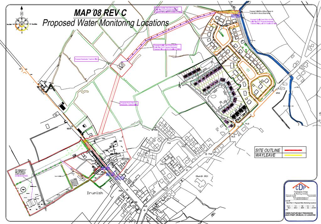
9 Attachment F2: Emissions Monitoring and Sampling Points It is proposed that the new WWTP will pipe the treated effluent discharge to the Mill Stream which is situated c.0.6km northeast of the site (SW4). It is proposed to monitor final effluent discharge from the discharge tank in accordance with Industrial Emissions licence requirements. Further details regarding the proposed final emission discharge monitoring are provided in Table F.3. It is proposed to monitor effluent discharge, storm water emissions, the emission to the sewer and the effluent that it is proposed by the Green Pasture Meat Processors to landspread. Further details regarding the proposed emission monitoring are provided in Table F.3. A map of proposed water emission monitoring locations are provided below.
10 Attachment F2: Water Emission Monitoring Locations Map 8 Rev. C. EPA Export :00:52:28
11 EPA Export :00:52:28
12 Attachment F.3: Tabular Data on Monitoring and Sampling Points Point Code Point Type Easting Northing Verified Pollutant Provide label ID s assigned in section F3 M=Monitoring S=Sampling 6E-digit GPS Irish National Grid Reference 6N-digit GPS Irish National Grid Reference SW1 M SW2 M SW3 M SW4 M BH1 M W1-1 M Y = GPS N = GPS not Y = GPS Y = GPS Y = GPS N = GPS not Y = GPS Y = GPS e.g. SO 2, HCl, NH 3 Storm water runoff (roof) Storm water runoff (roof) Storm water runoff (roof) Proposed effluent discharge (Mill Stream) Borehole Effluent EPA Export :00:52:28