Microreaction Engineering: Is small really better? Jan J. Lerou
|
|
|
- Tamsin Bethany Walton
- 5 years ago
- Views:
Transcription


1 Microreaction Engineering: Is small really better? Jan J. Lerou Velocys, Inc., Plain City OH
2 Overview Background Fundamentals Reaction Applications Scale up Methodology Summary 2
3 Background History In public domain since 1995 Definition of microstructured reactors 3 dimensional structures from sub mm to mm range Main characteristic: specific surface 10,000 50,000 m 2 /m 3 Potential benefits Process intensification Inherent process safety Broader reaction conditions incl. explosion regimes Distributed production Faster development 3
4 Background (cont.) Companies currently moving microchannel technology from R&D to commercialization: Degussa: running a demonstration project for the evaluation of microreaction technology or DEMiSTM for propylene epoxidation with hydrogen peroxide Clariant: opened its Competence Centre for Microreactor Technology (C3MRT) to increase efficiency, improve safety and reduce the costs of pharmaceutical synthesis Continuous pilot plan for the synthesis of azo pigments Axiva developed a process for continuous polymerization of acrylates (8 kg/h) using micro mixers Velocys 4


5 Enabling Technology Microchannels enable compact unit operations with high capacity per unit volume by reducing transport distances Microchannel ~ mm Characteristic dimension ~ mm Conventional 5
6 Conventional Reactors Steam Methane Reformer 20 million standard cubic feet/day ~30m x ~30m x ~30m Conventional Technology 6


7 Velocys Technology Reactors q Microchannel Steam Methane Reformer q Same capacity q 90% volume reduction q ~25% reduction in overall plant costs 7
8 Microchannel Hardware Performance Intense Heat Transfer Increases Productivity Convective Boiling Microchannel 1 20 W/cm W/cm 2 Conventional < 1 W/cm 2 < 1 W/cm 2 Fast Reactions Shrink Hardware Volume Gas phase Microchannel ms Conventional 1 10 seconds 8

9 Heat Transfer in Microchannels h = Nu d k Nu: Nusselt number h: Heat transfer coefficient d: Hydraulic diameter k: Thermal conductivity Velocys Heat Exchanger High surface area/volume ratio High heat transfer per volume Conventional Heat Exchanger Low surface area/volume ratio Low heat transfer per volume 9
10 Mass Transfer in Microchannels Sh ( d 2) D k τ diff A = = dd 2 Sh: : Sherwood Characteristic number diffusion time k A : d: Mass Hydraulic transfer diameter coefficient d: D: Hydraulic Diffusivity diameter D: Diffusivity τ convection = L vel avg : Characteristic convection time L: Flow length vel: average laminar velocity inlet outlet Diffusion across laminar streamlines (100<Re<2000) 10

11 Mass Transfer in Microchannels Velocys Conventional vs. flow ~ cm ~ cm ~ 0.02 cm ~ 0.2 cm Velocys technology enhances both intraparticle and and interparticle mass transfer 11
12 Low pressure drop Laminar flow in microchannels Orderly flow less fluctuations P L = f ( D h )µ V flow Laminar Flow Turbulent flow Random flow more fluctuations P L = f ( Dh ) µ ρ V flow (Blasius friction factor) 1.75 Turbulent Flow 12
13 Pressure Drop Case Study Pressure Drop (psi) Experimental DP Predicted DP Flow (SLPM) 48 channel device N 2, ambient Flow tot = 40 SLPM 40 x x Velocity = 4.2 m/s Re = 391 DP = 1.47 psig (model) DP = 1.51 psig (experimental) 13
14 Design for Reaction Applications Design for Constraints Pressure Drop Temperature / Materials Tailor Catalyst Form Match kinetics, heat removal, and pressure drop Select Thermal Management Method Convective heat transfer Phase change Chemical reaction 14


15 Conventional Catalyst Technology Powders for stirred tank or fluidized bed applications Extrudates for fixed bed applications Monoliths for gas purification applications 15


16 Catalysts for Microchannel Reactors Porous Metallic Felts Metallic Foils Microchannel Walls Metallic Fins ~ cm Metallic Foams 16
17 Catalyst Selection Strategy for Microchannel Reactors Pressure drop and dt allowable high Packed channels Flow through engineered slow structures Flow by engineered structures low fast kinetics Fin Fin coat coat Wall Wall coat coat 17
18 Endothermic Reaction Examples: Tailor flux and thermal profile air fuel reactant exhaust product Add heat by adjacent exothermic reaction Add heat by convective heat transfer Add heat by phase change 18
19 Thermal Performance: Endothermic Steam Reforming SMR Response Legend: Temperature Heat Flux Combustion Wall Axial Hea Flux (W/cm^2) SMR Axial Gas Temperature (C Normalized Distance 19


20 High Heat Transfer to Achieve Temperature Uniformity Temperature profile down typical Fischer Tropsch fixed bed reactor T 25 C Temperature profile down fixed bed Fischer Tropsch microchannel T 2 C 20
21 Velocys Technology Applications Reactions Methane Reforming Oxidation Dehydrogenation Fischer Tropsch Methanol Reactive Distillation Separations Thermal swing adsorption Distillation Mixing Emulsions Heat Exchange Compact Heat Exchangers LNG 21
22 Scale up q Manufacturable and Cost Effective Design q Sufficient Flow Distribution q Robust Operation q Integration with Commercial Plants 22
23 Velocys Scale up Methodology Cell Internal channel dimensions same as commercial chemical processor Number of channels increase; size of channels does not Gas flow Multi Cell Many channels lb/hr Full Scale >1000 channels lb/hr Full Scale Reactor is the basic building block of a commercial plant Full scale Reactor M U L T I C E L L C E L L 23

24 Commercial Microchannel Reactor: Summary for Hydrogen Generation Productivity 1MM SCFD H 2 per reactor Size ~0.6 m x 0.8 m x 0.6 m 2 tons >5000 channels Streams Air ~70 ºC Fuel ~70 ºC Reactant ~200 ºC Product ~300 ºC Exhaust ~300 ºC Emissions NO x < 10 ppm Meets California regulations Eighth scale Device 24

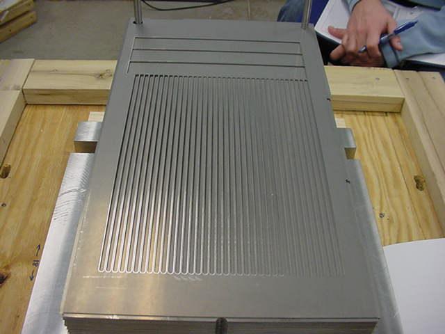
25 Manufacturable Design: Metal thinness creates microchannel dimension Shim Feature creation Wall shim without features Stacking Diffusion Bonding Machining Bonding creates hermetically sealed microchannels 25
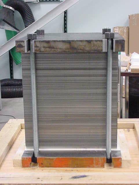

26 Device Manufacturing 26


27 Diffusion Bonding Large Stacks Protocol Time Temperature Pressure 27
28 Scale up Considerations q Manufacturable and Cost Effective Design q Sufficient Flow Distribution q Robust Operation q Integration with Commercial Plants 28


29 Tailor Pressure Drop in Flow Circuits To achieve sufficient flow distribution Inlet Q 1 m m m max min = max 100% 29

30 Flow Distribution Validation 30
31 Channel Flow Distribution Run 16: SLPM of air 1.0E E E 05 Mass flow rate (kg/s) 7.0E E E E E E E E+00 Model Experiment Channel number Sufficient flow flow distribution measured in in test test device 31
32 Manifold Model vs. Experiment dp Model Inlet pressure (psig) Experimental average Total air flow rate (SLPM) Predicted manifold pressure drop matches experiments 32
33 Scale up Considerations q Manufacturable and Cost Effective Design q Sufficient Flow Distribution q Robust Operation q Integration with Commercial Plants 33
34 Robust Performance to Upsets Recovery after combustion lost and catalyst in situ refurbishment Reactor performance 100% upset lost combustion 12 80% 10 60% 40% 20% CH4 conversion (%) Select i vit y t o CO ( %) SMR C balance (% change) 840 C equilibrium conversion 830 C equilibrium conversion Conditions: 3:1 S:C 23 atm 6 ms CT 9000 scfd H 2 upset SMR dp (psid, right axis) 0% % 0 Time on stream since refurbishment (hr) 34
35 Scale up Considerations q Manufacturable and Cost Effective Design q Sufficient Flow Distribution q Robust Operation q Integration with Commercial Plants 35

36 Microchannel Reactor Plant Interface Low cost standardized reactor assemblies: 5 to 30 full scale reactors in each assembly Shop built fabrication reduces construction costs and time Minimizes utility runs to cut installation costs Modular for additions of incremental capacity. 36
37 Summary Microchannel technology s advantages Tailored thermal profiles Optimized catalyst performance and form Enhanced selectivity Higher productivity Operation near stoichiometric feed ratio Model driven design and optimization process Scale up principles modeled and validated 37

 733 3300")
38 Contact Information Dr. Jan J. Lerou Manager, Experimental Operations Velocys Inc Corporate Blvd. Plain City, OH Phone: (614)