WEBINAR #5: Best Practices for Wet Compression. Call In Number: or Access Code: #
|
|
|
- Preston Sanders
- 5 years ago
- Views:
Transcription
1 WEBINAR SERIES: Turbine Inlet Cooling Best Practices WEBINAR #5: Best Practices for Wet Compression Sponsored by: Turbine Inlet Cooling Association Call In Number: or Access Code: #
2 Webinar Series co sponsored by Turbine Inlet Cooling Association Industry (end users, developers, engineers, etc.) looking to optimize and improve power generation and efficiency of the turbine inlets.


3 Agenda & Speakers Welcome Featured Topic Q&A Annette Dwyer Chair, TICA Munters Corporation Don Shepherd TICA Board Member Caldwell Energy Company
4 Who Are We? The Turbine Inlet Cooling Association (TICA) promotes the development and exchange of knowledge related to gas turbine inlet cooling (TIC) for enhancing power generation worldwide. TICA is a non profit organization. Turbine Inlet Cooling provides a cost effective, energyefficient, and environmentally beneficial means to enhance power generation capacity and efficiency of combustion/gas turbines during hot weather.

5 Who Are We? The TICA website includes technical and other details including a publicly available version of the TICA database of TIC installations and other information. Members enjoy expanded access to technical information Become a Member Today!!!
6 Turbine Inlet Cooling Technologies Webinar Schedule June 11, 2014 Best Practices for Wetted Media Evaporative Cooling August 13, 2014 Best Practices for Fogging Evaporative Cooling October 8, 2014 Best Practices for Chiller Systems December 12, 2014 Best Practices for Thermal Energy Storage February 11, 2015 Best Practices for Wet Compression April 8, 2015 Best Practices for Hybrid Systems
7 To avoid background noise, we will mute participants Please submit questions during the presentations by typing them into the chat window area of the screen After the featured presentation is complete, we will answer your submitted questions You may receive a online survey immediately following the webinar. We would appreciate your participation to: Provide feedback on webinar series Suggest other topics and speakers
8 Agenda: Why Cool Combustion Turbines (CT) How Wet Compression Works Components of Wet Compression systems Things to Consider before applying Wet Compression on CT s Quick Comparison to Other Cooling Technologies Why Apply Wet Compression on Combustion Turbines
9 Unfortunate Fundamental Characteristics of All Combustion Turbine Power Plants During hot weather, just when power demand is at it s peak. 1. CT Total Power output decreases up to 35% below rated capacity (Extent of the decrease depends on the CT design) 2. Efficiency decreases leading to increased fuel consumption (heat rate) and emissions per kwh..up to 15% more fuel consumed (Extent of the decrease depends on the CT design)
10 Why CT Power Output Capacity Decreases with Increase in Ambient Temperature? Power output of a turbine is proportional to the mass flow rate of hot gases from the combustor that enter the turbine Mass flow rate of combustor gases is proportional to the flow rate of the compressed air that enters the combustor Compressors provide compressed air and are volumetric machines, limited by the volumetric flow rate of inlet air they can pull or suck in As ambient temperature increases, the air density decreases. This results in a decrease of the mass air flow rate Reduced mass flow rate of inlet air reduces the mass flow rate of the combustor gases and hence reduced power out put of turbine
11 Why CT Efficiency Decreases with Increase in Ambient Temperature? Compressor of a CT system consumes almost two-third of the turbine s gross output Compressor requirement increases with increase in air temperature Increased power required by the compressor reduces the net electric power available from the CT system
12 Effect of Hot Weather on CT Generation Capacity Depends on CT Design 105% EFFECTS OF COMPRESSOR INLET AIR TEMPERATURE ON GAS TURBINE POWER OUTPUT PERIOD OF GREATEST DEMAND % OF RATED POWER 100% 95% 90% 85% ISO DESIGN POINT NEW AERO-DERIVATIVE POWER OUTPUT Compression Ratio = 30 OLD "FRAME" POWER OUTPUT Compression Ratio = 10 Up to 19% capacity loss at peak demand for this CT 80% COMPRESSOR INLET AIR TEMPERATURE, degrees F
13 Turbine Inlet Cooling Overcomes the Effects of the CT Characteristic During Hot Weather Rated Capacity With Wet Compression Net CT Power Output,% of Design With Cooling No Cooling With TIC No Cooling Rated Capacity Ambient Dry-Bulb Temperature, F
14 Why Use Wet Compression for Turbines Wet Compression (WC) provides a cost-effective and energy-efficient mean to increase a CT s output during hot weather Wet Compression is an environmentally beneficial means to enhance power generation capacity. Wet Compression is complementary to all other inlet cooling technologies Wet Compression is highly reliable, available when needed, with very low maintenance requirements
15 COMPRESSOR EFFICIENCY DRAMATICALLY IMPROVED Water Inter cools the CT compressor Mass flow enhancement Lower CDT allows more fuel to be fired (at constant firing temperature) Cools air to very near bell mouth Adiabatic Cooling of inlet air Can be operated with an existing fogger, evap cooler, or chiller upstream Overall net impact: MW on a GE 7EA, simple cycle
16 Base Case: 85% 95 / 75 F 1.75% Wet Compression: Air Fuel Air fuel +13% 1.75% H 2 O Gen Comp Turb Exhaust Gen Comp Turb Exhaust NOx 42 ppm Power +18% Most plants will not exceed 40 tons per year of Criteria Pollutants (NOx, SOx, CO, UHC), therefore not triggering NSR / PSSD NOx 38 ppm Flow + 2.5% Enthalpy + 10%
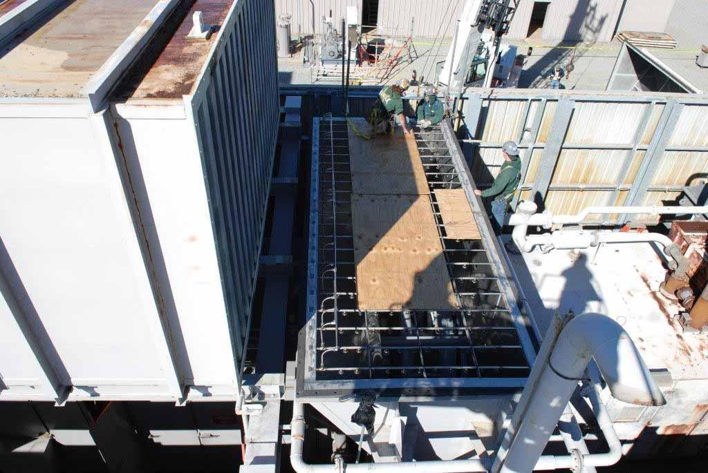
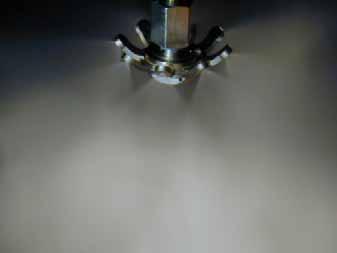
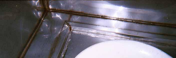
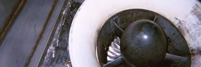
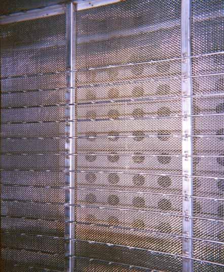
17 silencing panels Typical Fogging nozzle location Remove elbow for access, and line wetted surfaces w/ SS lining
18

19
20
21

22
23
24
25 Duct work condition Materials of construction Drain System Obstructions Lube Oil System Capacity Water leakage into Lube Oil System Generator Capacity
26 Rotor Grounding Guide vane Water Source Control System Integration 20 years of patented WC experience shows no failures This is not spray and pray
27 Although power augmentation not required in cold ambient conditions, a WC systems have been operated down to ~42 F, without bell mouth icing. Studies show maximum bell mouth temperature drop is <9 degrees. Most operators use temperature based permissive, such as 45, 50, 55, or 59 (F) Caldwell provides this low temp permissive at the time of controls commissioning.
28 HMI for normal system operation Start up, operation, shut down Emergency response Hardwired CWCT Trip on CT Trip Signal Fuel step change to CT on CWCT Trip Emission control interface with injection systems or dry low NOx combustion
29 Table 1: Performance Comparison of Various Combustion Turbines Combustion Turbine Siemens W501FC Siemens V84.2 GE LM2500PE GE Frame 6B SWPC W501D5A Alstom GT-24 GE Frame 7EA Overspray, % % Compressor Discharge Temperature Reduction, F Data not available Fuel Flow Increase, % N.D. N.D % Change in Base Load Firing Temperature, ºF No Change No Change No Change No Change No Change No Change No Change CT Power Increas e, MW Steam Turbine Power Increase, MW Simple Cycle Simple Cycle (est.) 2 (est.) 1.8(est.) Simple Cycle CT Heat Rate Improve ment, % N.D % NOx Info -10% N.D. -14% DLN DLN NoChange -24%
30 Why Use Wet Compression One of the most cost effective solutions Lowest first install cost Low operating costs Low maintenance cost Complementary to other cooling methods 10% to 20% Increase in output Better Heat Rate on Simple Cycle unit Simple To understand To maintain 100 s of successful installations Worldwide
31 Low Maintenance Drain and protect from freezing seasonally Clean discharge filters once a year Clean suction filters twice a year Change nozzles 4 to 5 yrs Replace or service pumps 3 to 5 yrs Calibrate Instruments once a year
32 Thank You And Don t Forget to Join TICA