From Concept to Product
|
|
|
- James Hodges
- 5 years ago
- Views:
Transcription
1 From Concept to Product Solar Thermal Development at the Weizmann Institute Jacob Karni Environmental & Energy Research Department Weizmann October 30,
2 The Problem Solar radiation is the most abundant energy source on earth. 2
3 The Problem Solar radiation is the most abundant energy source on earth. The cost of energy (electricity or fuel) produced from solar radiation is presently too high. 3
4 The Problem Solar radiation is the most abundant energy source on earth. The cost of energy (electricity or fuel) produced from solar radiation is presently too high. Solar radiation is an intermittent energy source, mostly available in desert areas. Large-scale use requires storage and transportation solutions. 4
5 Solar Technology Options Concentrated Solar Thermal Parabolic Trough Linear Fresnel Central Receiver (Solar Towers) Dish/Engine Systems Can be stored as heat or converted to fuel Photovoltaic Crystalline Silicon Thin Film (amorphous Si, CdTe, CIGS) Dye-Sensitized solar cells Concentrated Photovoltaic Can be converted to fuel
6 Observation The Photovoltaic Revolution: Years of fundamental research followed by development of production methods have reduced PV panel cost from ~$6/W to <$1/W over the last 5 years. 6
7 Observation The Photovoltaic Revolution: Years of fundamental research followed by development of production methods have reduced PV panel cost from ~$6/W to <$1/W over the last 5 years. No such progress in solar thermal. 7
8 Solar Thermal Electrical Power Generation 8
9 Solar Thermal Power Generation Concentrated solar thermal systems are used as electricity generating heat engines powered by the sun. 9
10 Solar Thermal Power Generation Concentrated solar thermal systems are used as electricity generating heat engines powered by the sun. The main components are Radiation collectors / concentrators Solar Receiver for heating a working fluid with solar radiation Engine for conversion of heat to electrical power 10


11 Line Concentration Systems Parabolic Troughs Most mature concentrated solar thermal technology Over 500 MWe installed Over 1000 MWe of new contracts issued Favorable unit size range MWe Commercial Trough System in California 11


12 Line Concentration Systems Linear Fresnel Reflectors Nearly mature concentrated solar thermal technology MWe installed or near completion Over 1000 MWe of new contracts issued Favorable unit size range MWe Linear Fresnel System in Australia 12


13 Solar Tower (Solar Central Receiver) MWe installed About 500 MWe in construction Favorable unit size range MWe 10MWe Demonstration SCR Plant in California 13


14 Dish Engine System No commercial installation About 20 MWe of contracts issued Favorable unit size range MWe Dish-Stirling Systems in Sandia National Lab., Albuquerque, New Mexico 14
15 Hybridization and Storage 15

16 Thermal Energy Storage or Hybridization Solar thermal storage and/or hybridization enables load-following of electricity demand Source: EPRI Electric Power Research Institute 16

17 Thermal Energy Storage and Hybridization 17

18 Thermal Storage Systems One commercial installation Excess heat from the solar field heats molten salts going from the cold tank to the hot tank. When needed, the heat from the hot tank is transferred to the steam generator. 18
19 Energy Transmission 19


20 Vision of possible HVDC lines linking the Southwest to the rest of the United States Source: Hank Price, US DOE,


21 Vision of possible HVDC lines linking North Africa to Europe Source: the DESERTEC Foundation
22 Game-Changing Solar Thermal Concepts 22


23 Solar Thermal Costs Are Mostly in Glass and Steel Trough Dish Increasing efficiency is the best way to decrease costs 23
.")
24 The Fletcher Principle of a Solar Heat Engine: Maximum Thermal to Electric Efficiency = Ideal Heat Engine Efficiency x Ideal Solar Receiver Efficiency Ideal Solar Heat Ideal Engine Solar Heat Efficiency Engine Efficiency 100% 90% 100% 90% 80% 80% 70% 70% 60% 60% 50% 50% 40% 40% 30% 30% 20% 20% 10% After Fletcher and Moen (1977). Trough C = x60 Trough x60 Solar Trough Tower C C = = x60 x500 Solar Tower x500 Dish Carnot C = x2,000 Carnot Carnot Carnot Edward E. Fletcher 0% Temperature [ C] Receiver Max. Efficiency = 1 - s[t(high) 4 - T(low) 4 ]/IC Heat Engine Max. efficiency = 1- T(low) / T(high) Ideal Solar Heat Engine Efficiency = (1- T(low) / T(high))*{1 - s[t(high) 4 - T(low) 4 ]/IC} 24
25 Optimum System Efficiency 100% 90% 80% 70% After Fletcher and Moen (1977). Carnot Ideal Solar Heat Engine Efficiency 60% 50% 40% 30% 20% Trough C = 60 Tower C = 500 Dish C = 2,000 C = Optical Concentration 10% 0% Temperature [ C] [ºC] A Dish can reach the highest system efficiency due to its high optical and solar conversion efficiencies 25
26 Solar System Efficiency Present & Future Source: J. Karni, Nature Materials, V. 10,
27 Possible Solution: Solarized Combined Cycle Dish Concentrator Solar Receiver, Gas Turbine & Generator Electrical Power to Grid Substation 1 27


28 Possible Solution: Solarized Combined Cycle Dish Concentrator Solar Receiver, Gas Turbine & Generator Hot Flow from Concentrators Storage Tank Steam Generator Cold Flow to Concentrators Condenser Steam Turbine & Generator Substation 2 Electrical Power to Grid Substation 1 28
29 Solar Combined Cycle Enabling Requirements Solar Receiver: Efficient energy transfer from highly concentrated solar radiation to working fluid at high temperature and pressure. Solar Concentrator: Main cost and system efficiency parameter. 29

30 Concentration Configuration Central Receiver System Development & Commercialization by Aora Solar 30

31 Concentration Configuration Dish Concentrator Low Cost Parabolic Dish Proprietary Volumetric Receiver System Development & Commercialization by HelioFocus 31
32 Solar-driven fuel production: General Concept Means to store and transport solar energy Key to Success: High efficiency and high reaction rate 32
33 Recycling CO2 emissions back to fuel using the sun as the energy source CO2 Power generation plant CO + O2 CO2 dissociation plant
 CO2 dissociation CO2 dissociation CO2 dissociation plant plant plant The larger the CO2 dissociation plant, the lower the carbon")
34 Emission Free Power Generation Electric Grid Generator Turbine Steam CO2 Coal Boiler P (1-X)MW CO Boiler P (X)MW CO2 Storage CO Storage Oxygen storage CO2 Dissociation Plant (CO2 CO+O2) CO2 dissociation CO2 dissociation CO2 dissociation plant plant plant The larger the CO2 dissociation plant, the lower the carbon emission

35 Providing liquid fuel for transportation using CO2 emissions as feedstock CO2 H2O Power generation plant O2 CO2 dissociation plant CO +H2 Methanol
MW Steam CO2 &")
 Storage Transportation Fuel")
36 Clean Coal Burning & CO 2 Conversion to Transportation Fuel Electric Grid Generator Emission Turbine Coal Boiler I P (1-X)MW Steam CO2 & Water Coal Boiler II P (X)MW Oxygen storage CO2 & Water Dissociation Plant CO2 & Water Storage Syngas (CO + H2) Storage Transportation Fuel Production
37 Reactor Design Concept Syngas CO 2 /H 2 O Heat Exchanger Syngas to Storage O 2 to Storage O 2 CO 2 /H 2 O Heat Exchanger H 2 O Inlet CO 2 Inlet CO & H 2 Exit Multi-Component Heat Exchanger Heat-to-Electricity Generating Device Concentrated Sunlight O 2 Exit Intermediate Electrode O 2 conducting membrane Thermionic Cathode CO 2 Inlet System Development & Commercialization by NewCO2Fuels H 2 O Inlet Anode 37
38 We can get it done, if 38


39 We can get it done, if we take the time to do it right 39
40 Supplement 40
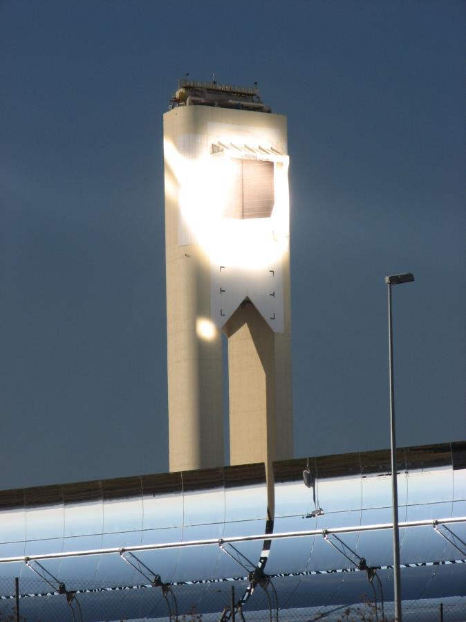
![Weizmann s Solar Laboratories [in operation since 1987] A 54m high Solar Tower with 64](/docs-images/90/103304824/images/41-2.jpg "Heliostats, each with 56m 2 of reflective area.")

41 Weizmann s Solar Laboratories [in operation since 1987] A 54m high Solar Tower with 64 Heliostats, each with 56m 2 of reflective area. Tower is set up as a laboratory, with 5 workstation, each capable of housing 2-3 experiments. Tests at the tower are conducted at a scale of 1 kw to 1 MW. Unique Tower Reflector enables the development of novel hightemperature solar chemistry systems. 41
42 Optical Characteristics Dish and Ideal Central Receiver Fresnel Reflectors Parabolic Dish Concentrator 42
43 Optical Characteristics Real Central Receiver Focal image increases by 1m per 100m distance due to sun-shape Focal image increases further as the rays angle of attack increases with distance from tower Heliostat spacings must increase with distance from target to avoid light blocking 43

44 The Real World 44
45 Consumption/1980 consumption Weizmann Growth of Electricity Consumption Over 3.5 billion people live in countries where consumption more than doubled from 1990 to 2003 Among them, over 1.5 billion people live in countries where consumption more than tripled at the same time India Egypt China U.K. Israel U.S. Norway Indonesia South Korea Thailand Vietnam Malaysia Year Source: DOE, Energy Information Administration, International Energy Annual
 Carbon Emission is high in the fastgrowing")
46 Per Capita Carbon Emissions Versus Per Capita GDP (Gross Domestic Product) Carbon Emission is high in the fastgrowing countries 46
47 The Fundamental Requirement of Electrical Power Supply: Get me what I want, when I want it!!! 47
48 Intermittent Energy Supply Does Not Match Load Requirements Case 1 Weizmann % Wind power fed into the power grid and total electricity output in the E.ON TSO area (Germany) 48
49 Intermittent Energy Supply Does Not Match Load Requirements Case 2 The TXU (Arizona) Load Requirement Load Required Wind Output 49
 Load Requirement Load Required Solar Output Wind Output")
50 Intermittent Energy Supply Does Not Match Load Requirements The TXU (Arizona) Load Requirement Load Required Solar Output Wind Output 50