ENVIRONMENTAL IMPACT ASSESSMENT AND ENVIRONMENTAL MANAGEMENT PLAN
|
|
|
- Tabitha Hensley
- 5 years ago
- Views:
Transcription
1 FINAL REPORT Rev.01_2018 ENVIRONMENTAL IMPACT ASSESSMENT AND ENVIRONMENTAL MANAGEMENT PLAN FOR Construction of additional Tankages for Ethanol (2x1000KL) and Biodiesel (1x1200KL) AT ROORKEE SMART TERMINAL, PLOT NO-4, LANDHAURA INDUSTRIAL AREA,UASIDC SITE, P.O.: LANDHAURA, ROORKEE, DISTT. HARIDWAR, UTTARAKHAND AREA-35 Acres. [ToR LETTER NO:IA-J-11011/443/2017-IA-II(I) dated 23rd January 2018] STUDY PERIOD: 1 ST DECEMBER 2017 TO 28 TH FEBRUARY 2018 MONITORING DONE BY M/S. VARDAN ENVIROLAB (NABL ACCREDITATIONT-6299, MOEFCC NO S.O (E) dated ) [Project or Activity 6(b)as per EIA Notification dated 14th Sept., 2006 and amended from time to time, the proposed project falls under category B,] ROORKEE SMART TERMINAL APPLICANT M/s Indian Oil Corporation Limited (Marketing Division) UPSO-II Address: Uttar Pradesh State Office-II(UPSO-II), E-8, Sector-1, NOIDA ENVIRONMENT CONSULTANT VARDAN ENVIRONET (QCI/NABET ACCREDITED NO. NABET/EIA/1619/RA0037) D-142, Sushant Lok-III SEC.57, GURGAON (HARYANA) vardanenviro165@gmail.com CONTACT: , DOCUMENT NO. 2017_VI_00024_FINAL EIA
2
3 VARDAN ENVIRONET 2017_VI_ DOCUMENT NO. REV SHEET 1 OF 14 ENVIRONMENTAL IMPACT ASSESSMENT & ENVIRONMENTAL MANAGEMENT PLAN FOR CONSTRUCTION OF ADDITIONAL TANKAGES AT ROORKEE TERMINAL, DISTRICT- HARIDWAR, UTTRAKHAND AREA- 35 ACRES [TOR LETTER NO: IA-J-11011/443/2017-IA-II(I) DATED 23 RD JANURAY 2018] STUDY PERIOD: 1 TH DECEMBER 2017 TO 28 TH FEBRUARY 2018 MONITORING DONE BY M/S. VARDAN ENVIROLAB (NABL ACCREDITATIONT-6299, MOEFCC NO S.O (E) DATED ) [PROJECT OR ACTIVITY 6(B) AS PER EIA NOTIFICATION DATED 14 TH SEPT., 2006 AND AMENDED FROM TIME TO TIME, THE PROJECT WAS APPLIED TO MOEF&CC UNDER CATEGORY "A" IN THE ABSENCE OF SEIAA/SEAC IN DEHRADUN] OF M/S INDIAN OIL CORPORATION LIMITED 1 May, 2018 FINAL EIA/EMP REPORT EIA Team P.K Naagori RS Yadav 0 March, 2018 DRAFT EIA/EMP REPORT EIA Team P.K Naagori RS Yadav REV DATE PURPOSE PREPARED REVIEWED APPROVED FORM NO. IA/UK/IND2/67857/2017
4 EIA/EMP FOR CONSTRUCTION OF ADDITIONAL TANKGES AT POL TERMINAL OF M/S IOCL, ROORKEE (U.K) 2017_VI_ DOCUMENT NO. REV SHEET 2 OF 14 Document No. 2017_VI_0024_FinalEIA C O N T E N T S CHAPTER DESCRIPTION PAGE - Review and Revision History i - NABET Annexure ii-vii - Standard TOR granted on 23 Jan Compliance of TOR i-xxiv 1.0 INTRODUCTION 1 of Purpose of The Report 2 of Identification of The Project and Project Proponent 3 of Identification of the Project 3 of Identification of the Project Proponent-IOCL as POL Terminal 4 of Project Cost & Completion Schedule 4 of Brief Description of Nature, Size, Location of the Project 4 of Importance to The Country and Region 10 of Scope of the Study- Details of Regulatory scoping Carried Out (As Per 11 of 200 ToR) Methodology for Environmental Impact Assessment 12 of Structure of the Report 12 of Laws applicable to this Project 14 of PROJECT DESCRIPTION 15 of Type of project 15 of Need/justification of project 15 of Justification 15 of Location of project (maps showing general location, specific locations, project boundary and project site layout) 16 of Size or magnitude of operation 19 of Salient features of the project 22 of Project description 26 of Receipt of Petroleum Product 26 of Storage 27 of Dispatch/Distribution / loading by tank trucks 28 of Tank lorry filling / parking 29 of TLF / TLD pumps 29 of Pipeline network 29 of Fire protection system 29 of Electrical facilities 30 of Source of electrical power 30 of Electrical equipment associated with power distribution 30 of Terminal automation 32 of Waste water treatment 32 of Internal communication system 32 of Availability of water, its source, energy/ power requirement and source 33 of Water requirement 33 of Power 33 of Manpower requirement 33 of 200
5 EIA/EMP FOR CONSTRUCTION OF ADDITIONAL TANKGES AT POL TERMINAL OF M/S IOCL, ROORKEE (U.K) 2017_VI_ DOCUMENT NO. REV SHEET 3 OF Land requirement 33 of Source of pollution and control measures 34 of Waste water generation & treatment 34 of Air pollution 34 of Solid waste management 34 of Noise pollution 35 of Description of Mitigation Measure Incorporated in to the Project to meet Environmental Standard, Environmental Operating Conditions or 35 of 200 other EIA Requirements 3.0 DESCRIPTION OF ENVIRONMENT 36 of Study Area 36 of Study Period 36 of Components and Methodology 36 of Establishment of Baseline for Valued Environmental Components, As Identified in the scope 37 of Meteorological Data 37 of Wind 38 of Wind Rose 38 of AIR QUALITY 40 of Analytical Techniques for Air Quality Monitoring 40 of Air Quality Monitoring 40 of Methodology Adopted for the Study 40 of Observations 42 of NOISE ENVIRONMENT 47 of Noise Analysis within the Study Area 47 of Observations 48 of SOIL ENVIRONMENT 50 of Soil Quality and Characteristics 50 of Criteria Adopted for Selection of Sampling Locations 50 of Methodology and Sampling 50 of Soil Sampling Locations 50 of Observations 53 of WATER ENVIRONMENT 53 of Observations 61 of Land use and Land cover 61 of Land Use Pattern of the Study area 61 of Data Used 61 of Methodology Adopted for Thematic Data Extraction from the Satellite Imageries 61 of Geology 65 of Hydrogeology 65 of Topography 68 of Climate 68 of Seismicity 68 of Flood Hazard Zonation of the Area 69 of TRAFFIC STUDY 71 of Conclusion 72 of 200 Document No. 2017_VI_0024_FinalEIA
6 EIA/EMP FOR CONSTRUCTION OF ADDITIONAL TANKGES AT POL TERMINAL OF M/S IOCL, ROORKEE (U.K) 2017_VI_ DOCUMENT NO. REV SHEET 4 OF SOCIO-ECONOMIC ENVIRONMENT 74 of Baseline Status 74 of Demographic Structure 75 of Occupational Pattern/ Economic Resource Base 76 of Infrastructure Resource Base 77 of Economic Resource Base 78 of Cultural and Aesthetic Attributes 79 of Socio-economic Survey 79 of Methodology applied for selection of sample & data collection 79 of Field Survey and Observations 79 of BIOLOGICAL ENVIRONMENT 86 of Introduction 86 of Study Area 87 of Methodology adopted 89 of Assessment of Rare, Endangered and threatened Flora and Fauna 90 of Assessment of sensitive habitat 90 of Observation and Results 90 of Agricultural Crops 99 of Rare and endangered flora in the study area 100 of Fauna 100 of Faunal diversity of the study area 100 of Biodiversity 100 of Study Area (to check) 104 of Conclusion 106 of ANTICIPATED ENVIRONMENTAL IMPACT AND MITIGATION MEASURES 107 of Land Environment 107 of Source of Impact 107 of Impact Assessment 108 of Impact on land use 108 of Impact on Air Environment 108 of Sources of Impact 108 of Impact Assessment 109 of Air Quality Modelling 109 of ISCST3 Dispersion Modelling 109 of Meteorological Data 112 of Results 113 of Impacts 117 of Mitigation Measures 117 of References 117 of Impact on Water Environment 117 of Source of Impact 117 of Impact Assessment 119 of Impact on Noise Environment 119 of Mitigation Measures 119 of Impact on Biological Environment 119 of Flora 119 of 200 Document No. 2017_VI_0024_FinalEIA
7 EIA/EMP FOR CONSTRUCTION OF ADDITIONAL TANKGES AT POL TERMINAL OF M/S IOCL, ROORKEE (U.K) 2017_VI_ DOCUMENT NO. REV SHEET 5 OF Fauna 119 of Impact Assessment 119 of Impact of Solid and Hazardous Waste 119 of Risk Assessment during Construction 120 of Impact on Socio-Economic Environment 120 of Mitigation Measures of Socio Economic Environment 121 of Overall Evaluation of Impacts 122 of CONCLUSION 122 of 200 Document No. 2017_VI_0024_FinalEIA 123 OF ANALYSIS OF ALTERNATIVE (TECHNOLOGY & SITE) 5.1 Introduction 123 of Analysis of alternative site 123 of Alternative for Technology and other Parameters 123 of ENVIRONMENTAL MONITORING PROGRAM 124 of INTRODUCTION 124 of Environmental Management Cell 124 of Meteorology 124 of Monitoring Points / Locations and Components 125 of Monitoring Parameters and Frequency 126 of Monitoring Methodologies 126 of Reporting and Documentation 126 of Budget and Procurement Schedule 127 of Budget Occupational Health and Safety work 127 of ADDITIONAL STUDIES 128 of RISK analysis 128 of Preamble 128 of OBJECTIVE 128 of SCOPE OF THE STUDY 128 of Hazard Identification 128 of Consequence Analysis 128 of Glossary of Terms Used in Risk Assessment 129 of Scope of Study 129 of APPROACH TO THE STUDY 130 of Hazard Identification 131 of Introduction 131 of Classification of Major Hazardous Substance 131 of DOW INDEX 131 of Fire Explosion and Toxicity Index (FE & TI) Approach 131 of FE and TI Methodology 132 of Computations and Evaluation of Fire and Explosion Index 132 of Toxicity Index (TI) 132 of Classification of Hazard Categories 132 of The Basic Data 132 of Basic Data for MS 133 of Basic Data for SKO 133 of Basic Data for HSD 133 of Basic Data for Ethanol 133 of 200
8 EIA/EMP FOR CONSTRUCTION OF ADDITIONAL TANKGES AT POL TERMINAL OF M/S IOCL, ROORKEE (U.K) 2017_VI_ DOCUMENT NO. REV SHEET 6 OF Basic Data for Biodiesel 133 of The Properties 133 of The Results 133 of Comments 133 of RISK ANALYSIS 134 of Properties of Materials Handled 134 of Hazards of Equipment/Pipeline Handling Petroleum Products 134 of Brief Review of Safety Related Facilities 135 of Fire Fighting Facilities 135 of Safety Valves 135 of Risk Assessment 136 of Introduction 136 of Modes of Failure 136 of Damage Criteria 136 of Dispersion and Stability Class 138 of Selected Failure Cases 138 of Consequence Analysis 139 of Storage Tanks on Fire 139 of Vessel connection failure for tank outlet lines 140 of TLF/TLD Pump Discharge Line Rupture 142 of Gasket Failure in TLF Pump Discharge Line 144 of inches dia. loading arm failure for Road Tanker Loading 145 of Pump Mechanical Seal Failure 146 of Hole in TLF Pump Discharge Line (15mm) 147 of RISKS AND Failure Probability 149 of RISK ASSESSMENT 150 of ACCEPTABILITY OF RISK 150 of Conclusions & Recommendations 151 of Conclusion 151 of Recommendations 151 of Disaster Management Plan 153 of Introduction 153 of Statutory Requirement 153 of Objective of Disaster Management Plan 153 of Definitions 154 of Description of Industrial Activity 154 of Safety Related Utilities 155 of Disaster Planning 155 of Identification of hazards 156 of General Nature of Hazard 157 of Hazards Areas of the Plant 157 of Hazard Scenarios and effects. 157 of Safety Related Components provided in the Terminal 157 of safety related measures right in the design stage 158 of Other Safety Measures 158 of Details of Fire Fighting Facilities 158 of Emergency Control Centre & Shelter Room 161 of 200 Document No. 2017_VI_0024_FinalEIA
9 EIA/EMP FOR CONSTRUCTION OF ADDITIONAL TANKGES AT POL TERMINAL OF M/S IOCL, ROORKEE (U.K) 2017_VI_ DOCUMENT NO. REV SHEET 7 OF Alarm and Communication System 161 of Mutual Aid 161 of Disaster Control Plan 161 of Equipment Planning 161 of Organization Plan 161 of Action Plan 164 of Disaster Combating Action Plan with specific reference to the team 166 of Role Orders for Disaster Combating Action Plan 167 of Action Plan for Specific Cases 168 of Important Telephone Numbers: 174 of PROJECT BENEFITS 175 of Other Benefits of Roorkee Terminal 175 of Corporate Social Responsibility 176 of ENVIRONMENTAL COST BENEFIT ANALYSIS 177 of ENVIRONMENT MANAGEMENT PLAN 178 of ENVIRONMENTAL MANAGEMENT 178 of MANAGEMENT PLAN DURING CONSTRUCTION PHASE 178 of Site Preparation 179 of Sanitation 179 of Construction Equipment & Waste 179 of Storage of Hazardous Materials 179 of Solid / Hazardous Waste Disposal 179 of Management PLAN during Operation Phase 179 of Air Environment 179 of WATER ENVIRONMENT 180 of Waste Water Generation 180 of Waste Water Treatment & Disposal 180 of Oil Water Separator / Oil Trap 180 of Rain Water Harvesting System 180 of NOISE ENVIRONMENT 181 of Sources of Noise 181 of Control of Noise 181 of SOLID WASTE MANAGEMENT 182 of Land Losers / Ousters 182 of AFFORESTATION 182 of SAFETY & FIRE FIGHTING 182 of Safety 182 of Fire Fighting Facilities 183 of Safety Organization 183 of Security 183 of Safety & Environmental Audit 183 of Occupational Safety and Health 183 of Tools & Tackles 184 of Preventive Maintenance & Planned Inspection 184 of Budget for Environmental Management Plan 185 of SUMMARY AND CONCLUSION 186 of INTRODUCTION 186 of 200 Document No. 2017_VI_0024_FinalEIA
10 EIA/EMP FOR CONSTRUCTION OF ADDITIONAL TANKGES AT POL TERMINAL OF M/S IOCL, ROORKEE (U.K) 2017_VI_ DOCUMENT NO. REV SHEET 8 OF STRUCTURE OF EIA REPORT 186 of PROJECT PROPOSAL 187 of PROJECT COST & COMPLETION SCHEDULE 188 of PROJECT LOCATION 188 of BENEFITS OF PROPOSED PROJECT 188 of OBJECTIVE OF EIA STUDY 189 of SCOPE OF EIA STUDY 189 of PROJECT DESCRIPTION 189 of PROCESS DESCRIPTION 191 of DESCRIPTION OF ENVIRONMENT & IDENTIFICATION OF ANTICIPATED 191 of 200 IMPACT CLIMATE & METEOROLOGY 191 of AIR ENVIRONMENT 192 of NOISE ENVIRONMENT 192 of SOIL ENVIRONMENT 194 of WATER ENVIRONMENT 194 of BIOLOGICAL ENVIRONMENT 195 of SOCIO-ECONOMIC ENVIRONMENT 196 of TRAFFIC ENVIRONMENT 196 of ANALAYSIS OF ALTERNATIVE (TECHNOLOGY & SITE) 196 of ENVIRONMENTAL MONITORING PROGRAMME 196 of Additional Studies 197 of 200 ENVIRONMENTAL MANAGEMENT PLAN DURING CONSTRUCTION 197 of PHASE MANAGEMENT PLAN DURING OPERATION PHASE 197 of CONCLUSION 199 of DISCLOSURE OF CONSULTANT ENGAGED 200 of 200 Document No. 2017_VI_0024_FinalEIA LIST OF TABLES Table No. List of Table Page No. 1.1 Project and Environmental Settings 4 of Status of previous three months for receipt, blending and dispatch of petroleum products 10 of Salient Features of the Terminal 22 of Details of existing and proposed tankages 27 of Details of Road Tanker Loading 28 of Details of TLF PUMPS 29 of Details regarding the D.G. Sets 31 of Water Consumption Detail of Existing Facilities 33 of Power Consumption Detail of Existing Facilities 33 of Land Requirement 34 of 200
11 EIA/EMP FOR CONSTRUCTION OF ADDITIONAL TANKGES AT POL TERMINAL OF M/S IOCL, ROORKEE (U.K) 2017_VI_ DOCUMENT NO. REV SHEET 9 OF Quantity of waste authorization 34 of Standard limit for Noise Level in db(a)leq 35 of Onsite Meteorological Data (Period: 1st Dec, 2017 to 28th Feb, 2018) 38 of Procedures for Determining Various Air Quality Parameters 40 of Ambient Air Quality Monitoring Sampling Stations 41 of Ambient Air Quality Monitoring Results 42 of Noise Monitoring Sampling Stations 47 of Noise Monitoring Result (1st Dec, 2017 to 28th Feb, 2018) 48 of Soil Sample Monitoring Station 50 of Soil Analysis Result (1st Dec, 2017 to 28th Feb, 2018) 52 of Ground Water Sampling Stations 54 of Ground Water Analysis Result (1st Dec, 2017 to 28th Feb, 2018) 55 of Surface Water Sampling Stations 57 of Surface Water Sampling Results (1st Dec, 2017 to 28th Feb, 2018) 58 of Land use break up 62 of The average rainfall of the area 68 of Highway in the Study Area 71 of No. of Vehicles per Day 71 of Existing Traffic Scenario and LOS 71 of During Plant Operation 72 of Modified Traffic Scenarios and LOS 72 of List of the villages for field survey of socio-economic environment 82 of Summarized demographic structure of the study area 82 of Demographic structure of the study area 83 of Occupational structure of the study area 84 of Infrastructure resource base of the study area 85 of Abbreviations 86 of Sampling Locations for Biological Environment 87 of List of existing floristic composition within Core zone of project site 91 of List of floral composition encountered within Buffer zone 10 km radius) of project study 94 of Statistical Synopsis of Floristic composition of Buffer zone 99 of List of fauna in the core area (to check) 101 of Faunal Diversity in the buffer zone of the Study Area 101 of Dispersion parameters as per stability class 111 of Predicted GLC of PM10 at Ambient Air Quality Monitoring Stations 113 of WHO Recommendation Per Head Per Day 117 of WATER CONSUMPTION 118 of Waste Water Generation & Disposal 118 of Qualitative Effects on Socio-economic Environment 121 of 200 Document No. 2017_VI_0024_FinalEIA
12 EIA/EMP FOR CONSTRUCTION OF ADDITIONAL TANKGES AT POL TERMINAL OF M/S IOCL, ROORKEE (U.K) 2017_VI_ DOCUMENT NO. REV SHEET 10 OF EVALUATION OF IMPACTS 122 of Post Project Environmental Monitoring Locations 125 of Post Project Environmental Monitoring parameters and frequency of monitoring 126 of Fire, Explosion and Toxicity Index 132 of Properties of MS, SKO, HSD, Ethanol and Biodiesel 134 of Calculation for Dow Fire and Explosion Index 134 of Damage due to incident thermal radiation Intensity 137 of Physiological effects of threshold Thermal Doses 137 of Damage effects due to blast over pressure 138 of List of Failure cases 138 of Hazard Distances Due to Pool Fire in Storage Tanks 139 of Hazard Distances Due to Pool Fire for Vessel Connection Failure 141 of Hazard Distances Due to Unconfined Vapour Cloud Explosion (MS) 142 of Hazard Distances Due to Pool Fire for TLF/TLD 142 of Hazard Distances due To MS Pump Discharge Line Rupture 143 of Hazard Distances to Pool Fire due to Failure of Gaskets in TLF Pump Discharge Lines 144 of Hazard distances to UVCE due to MS pump (TLF)discharge line gasket failure 145 of Hazard distances due to loading arm failure (TLF) 145 of Hazard distances due to UVCE (MS) 146 of Hazard distances to thermal radiation due to pool fire for pump mechanical seal failure 147 of Hazard distances due to UVCE(MS) 147 of Hazard distances to pool fire due to hole in pump discharge line (15 mm) 148 of Hazard distances due to MS pump discharge line hole (15mm) 149 of Failure Frequency Data 149 of Individual Risk of some Human Activities 151 of List of Failure cases 157 of List of Important Telephones Numbers 174 of Details of DG sets 180 of Noise Level of Different sources 181 of EMP cost Details 185 of Project at a glance 187 of Details of Project Proposal 186 of Details of existing and proposed tankages 190 of a Onsite Meteorological Data (Period: 1st December 2017 to 28th February, 2018) 192 of Summary of Ambient Air Quality Results 192 of Summary of Observations of Water Quality 194 of 200 Document No. 2017_VI_0024_FinalEIA
13 EIA/EMP FOR CONSTRUCTION OF ADDITIONAL TANKGES AT POL TERMINAL OF M/S IOCL, ROORKEE (U.K) 2017_VI_ DOCUMENT NO. REV SHEET 11 OF Water Consumption 195 of Wastewater Generation 195 of 200 LIST OF FIGURES FIGURE NO. DESCRIPTION PAGE NO. 1.1 Key Plan showing 10 km Radius of Roorkee Terminal of M/s IOCL 8 of Digitized Map of Study Area 9 of Location of the Project 16 of Google Image of project Site 17 of Route map of the Project Site 18 of Photographs showing the Roorkee Terminal 19 of Location map on Google 20 of Layout Plan of Roorkee POL Terminal 21 of Process Flow Diagram of Roorkee POL Terminal of M/s IOCL 27 of Wind Rose Diagram of Study Period (1st Dec, 2017 to 28th Feb, 2018) 39 of Photographs of Air quality Monitoring 41 of Graph Showing Pollutants Concentration of the Study Area 45 of Key Plan of Air Monitoring Stations 46 of Photographs of Noise Monitoring 47 of Graph Showing Noise Pollutants Concentration of the Study Area 48 of Key Plan of Noise Monitoring Station 49 of Photographs of Soil Sampling 50 of Key Plan of Soil Sampling Stations 51 of Photographs of Noise Monitoring 47 of Graph Showing Noise Pollutants Concentration of the Study Area 48 of Key Plan of Noise Monitoring Station 49 of Photographs of Soil Sampling 50 of Key Plan of Soil Sampling Stations 51 of Photograph of Water sampling 54 of Key Plan of Water Sampling Stations 60 of Methodology Used for Land use Classification and Mapping 62 of Land Use Pattern of Study area 63 of False color composite (FCC) image of study area 64 of Drainage map of Study area 66 of Contour Map of Study Area 67 of Map showing seismic zones of India 69 of Flood Hazard Zonation Map of the area 70 of Road transportation map of project site 73 of Bar diagram representing the ratio of population in the study area 81 of Literacy rate of the study area 81 of Bar Diagram Representing the Percentage of category of Workers 82 of Map of survey locations for Biological Environment 88 of Photographs for Biological Environment 89 of Comparatives of habit composition on both zone (Core & Buffer) within 98 of km study area Document No. 2017_VI_0024_FinalEIA
14 EIA/EMP FOR CONSTRUCTION OF ADDITIONAL TANKGES AT POL TERMINAL OF M/S IOCL, ROORKEE (U.K) 2017_VI_ DOCUMENT NO. REV SHEET 12 OF Map showing Nearest Protected area from proposed project boundary 105 of Gaussian Plume Model 111 of Wind rose Diagram 112 of Spatial distribution of predicted GLCs of PM of Spatial distribution of predicted GLCs of SO2 115 of Spatial distribution of predicted GLCs of NOx 116 of Flow Chart of Environment Management Cell 127 of Green belt development by IOCL Roorkee Terminal 181 of Health check-up camp organized by Roorkee Terminal 184 of Flow Chart of Environment Management Cell 127 of Green belt development by IOCL Roorkee Terminal 181 of Health check-up camp organized by Roorkee Terminal 184 of 200 LIST OF ANNEXURES S. No DESCRIPTION I Reference documents, MOEFCC O.M dated 27th April, 2018 for Public Hearing Exemption. II Factory License of Roorkee Terminal for the period to III PESO Licence of Roorkee Terminal for the Period 25/10/2016 to 31/12/2019. IV CTO letter of Roorkee Terminal for period V List of nearby Major Industries with SIDCUL Layout VI Previous EC Letter via Letter with receipt of compliance of Roorkee Terminal Vardan Envirolab, Gurgaon {NABL Accredited Lab, Certificate No. TC- VII 6299 in lieu of T-2629 dated , MOEFCC NO. S.O (E) dated (Pages 12) VIII Vardan EnvironLab Report for Air, Noise, Soil and Water IX Micrometeorology data and Temperature & Humidity Graphs X Latest DG sets and Fire Engine Monitoring Report of IOCL Roorkee Terminal XI DG Sets Stack and Fire Engine Monitoring Reports of IOCL Roorkee (Pages 9) XII Latest OWS Lab report of IOCL Roorkee Terminal XIII Layout and all drawing of Roorkee Terminal of M/s IOCL XIV Iso-Risk Contour FN Curve and all Damage contours of selected Failure cases in Risk Analysis of Roorkee Terminal (Drawing No.1 to 41) XV HSE Policy of Roorkee Terminal of M/s IOCL XVI Fire Organisation Chart of M/s IOCL Roorkee Terminal XVII Mutual aid meeting-2017 of IOCL Roorkee Terminal XVIII Health and safety Inspection Report of M/s IOCL Roorkee Terminal XIX Electricity Bill connection of Roorkee Terminal of M/s IOCL XX Water Balance diagram of IOCL Roorkee Terminal XXI List of MSDS of MS, SKO, HSD and Ethanol XXII Previous CTE of Roorkee Terminal of M/s IOCL Document No. 2017_VI_0024_FinalEIA
15 EIA/EMP FOR CONSTRUCTION OF ADDITIONAL TANKGES AT POL TERMINAL OF M/S IOCL, ROORKEE (U.K) 2017_VI_ DOCUMENT NO. REV SHEET 13 OF 14 EIA MSMEs MoEF& CC SEIAA US EPA EMC EMP AAQM APCD FRVT CRVT PMCC CPCB OHSAS PESO CCoE PPE db DG ECC EPA ETP FCC GC GIS GLC GPS HPLC IMD IRS ISCST ISO ISS KLD kva KW LISS NO 2 ppm LIST OF ABBREVIATIONS Environmental Impact Assessment Micro, Small and Medium Enterprises Ministry of Environment, Forest & Climate Change State Level Environmental Assessment Authority United State Environmental Protection Agencies Environmental Management Cell Environmental Management Plan Ambient Air Quality Monitoring Air Pollution Control Devices Floated Roof Vertical Tank Conical Roof Vertical Tank Power cum motor control Centre Central Pollution Control Board Occupational Health & Safety Assessment Petroleum, Explosives and safety Organisation Chief Controller of Explosives Personal Protective Equipment Decibel Diesel Generator Emergency Control Centre Environmental Protection Agency Effluent treatment plant False Colour Composite Gas Chromatography Geological Information System Ground level concentration Global Positioning System High pressure Liquid Chromatography Indian Meteorological Department Indian Remote Sensing Satellite Industrial Source Complex, Short Terms International Organization of Standardization Indian Standard Specification Kilo Litre Per Day Kilo Volt Ampere Kilo Watt Linear Imaging Self Scanning Sensor Nitrogen Dioxides Part Per Million Document No. 2017_VI_0024_FinalEIA
16 EIA/EMP FOR CONSTRUCTION OF ADDITIONAL TANKGES AT POL TERMINAL OF M/S IOCL, ROORKEE (U.K) 2017_VI_ DOCUMENT NO. REV SHEET 14 OF 14 R&R RDS RPM RSPM NH SO 2 SOI SOPs SPCB SPM SSE SSW STP TAC TPA TOR TPH TDS m bgl ug/m 3 mrl w.e.f. w.r.t. w/w cm km mg m Rehabilitation & Resettlement Respirable Dust Sampler Respirable Particulate Matter Respirable Suspended Particulate Matter National Highway Sulphur-di-Oxide Survey of India Standard Operating Procedures State Pollution Control Board Suspended Particulate Matter South of South-East South of South-West Sewage Treatment plant Traffic Advisory Committee Tone Per Hour Terms of Reference Tones Per Hour Total Dissolved Solid Meter Below Ground Level Micro gram per meter cube Mean Reference Level With Effective From With Reference To Weight by Weight Centimetre Kilometre Milligram Meter Document No. 2017_VI_0024_FinalEIA
17 Roorkee (Uttarakhand) of M/s Indian Oil Corporation Limited(IOCL) Final EIA/EMP Report REVIEW AND REVISION HISTORY History of revisions of the present report: Table I: History of the Revisions Rev. Date Modifications Remarks Rev.00 Draft Draft EIA /EMP Report Report has been prepared by Team Vardan and all the comments of reviewers have been incorporated in Draft EIA/EMP report. Rev.01 Final Final EIA/EMP Report Report has been prepared by Team Vardan and all the comments of reviewers have been incorporated in Final EIA/EMP report. Document No.2017_VI_0024_FINAL EIA Table II: Record of Review Rev. Date Description Review-1 Approval Rev Draft EIA /EMP Mr. P.K. Naagori Mr. R.S. Yadav Report Rev Final EIA /EMP Report Mr. P.K. Naagori Mr. R.S. Yadav This Report has been prepared by Vardan EnviroNet on behalf of M/s Indian Oil Corporation Limited(IOCL) with due consideration and skill as per our general terms and conditions of business and terms of agreement with the M/s Indian Oil Corporation Limited(IOCL) DISCLAIMER Vardan EnviroNet has taken all reasonable precautions in the preparation of this report as per its auditable quality plan. Vardan EnviroNet also believes that the facts presented in the report are accurate as on the date it was written. However, it is impossible to dismiss absolutely, the possibility of errors or omissions. Vardan EnviroNet therefore specifically disclaims any liability resulting from the use or application of the information contained in this report. The information is not intended to serve as legal advice related to the individual situation. M/s Vardan EnviroNet, D-142, Sec. 57 Gurgaon, Haryana Page i(revision History)
18 QCI-NABET Scheme for accreditation of EIA Consultant Organisations/Version 3/June 2015 DECLARATION BY CONSULTANT NABET Annexure VII Declaration by Experts contributing to the EIA of M/s Indian Oil Corporation Limited(MD), Roorkee POL Terminal at village-landhaura and UASIDC site, P.O.: Landhaura, Roorkee, Distt. Haridwar, Uttarakhand Declaration by Experts contributing to the EIA: I, hereby certify that I was part of the EIA team in the following capacity that developed the above EIA. EIA Co-ordinator: Name :Mr. Paras Kumar Naagori Signature & Date : Period of involvement :November,2017 Till Date Contact information :D-142, Sector-57, Sushant Lok-III, Golf Course Extension Road, Gurgaon (Haryana) Contact no: vardanenviro165@gmail.com Functional Area Experts (FAEs): S. No. Functional Areas Name of the expert/s Involvement during Signature &Date 1. AP FAE: Mr. S.K Sharma November, 2017 Till date a) Identifying the sources of emissions and mitigation measures. b) Site-specific micro meteorology monitoring. C) Ambient Air Quality (AAQ) monitoring Document No. 2017_VI_0024 Final EIA/EMP Page ii
19 QCI-NABET Scheme for accreditation of EIA Consultant Organisations/Version 3/June 2015 DECLARATION BY CONSULTANT Impact predictions and mitigations. d) Impact identification 2. WP FAE: Mr. S.K Sharma November, 2017 Till date a) Selection of sampling locations b) Groundwater quality monitoring and assessment, impacts on water environment and mitigations. c)identification, characterisation of effluent and treatments there of d)water balance and conservation measures 3. SHW FAE: Mr. S. K Sharma November, 2017 Till date a) Identification of haz, solid w.g, and their disposal and mitigation measure. b) Recycling and disposal 4. SE FAE: Ms. Shilpa Mishra November, 2017 Till date a) Determination of demographic profile including socio economy & livelihood b) Assessing the changes in socio economic pattern 5. EB Dr. Vivek Tiwari a) Biological environment status in respect of terrestrial fauna and aquatic eco system b) Impact on ecological environment Document No. 2017_VI_0024 Final EIA/EMP Page iii
20 QCI-NABET Scheme for accreditation of EIA Consultant Organisations/Version 3/June 2015 DECLARATION BY CONSULTANT 6. HG/Geo FAE: Mr. R. S Yadav November, 2017 Till date a) Ground water resource assessment b) Impact on ground water potential and mitigation measures for avoiding ground water contamination. 7. AQ FAE: Mr. Surbhi Makhwana FAA: Miss. AviTomar 8. NV FAE: Mr. Paras Kumar Naagori November, 2017 Till date a) Processing of site specific micro-meteorological data. b) Collection and use of data for modelling. c) Air dispersion modelling for prediction of GLCS due to PM 10, S0 2 and Nox a) Analysis of ambient noise quality data b) Impact due to plant noise and abatement measures 9. LU FAE: Mr. Ankur Agrawal a) Analysis of data related to land use pattern b) Land use map development. c) Impact on land environment in respect to land form change Document No. 2017_VI_0024 Final EIA/EMP Page iv
21 QCI-NABET Scheme for accreditation of EIA Consultant Organisations/Version 3/June 2015 DECLARATION BY CONSULTANT 10. RH 11. SC FAE: Mrs. Anuradha Sharma FAE: Mr. S.K Sharma November, 2017 Till date a) Identification of hazardous prone areas b) Environment risk evaluation c) On-site and Off-site emergency planning November, 2017 Till date a) Monitoring, analysis and characterisation of soil b) Assessment of impact on soil quality and mitigation measure. Document No. 2017_VI_0024 Final EIA/EMP Page v
22 QCI-NABET Scheme for accreditation of EIA Consultant Organisations/Version 3/June 2015 DECLARATION BY CONSULTANT Declaration by the Head of the accredited consultant organization/ authorized person I, R.S. Yadav, hereby confirm that the above mentioned Roorkee POL Terminal of M/s Indian Oil Corporation Limited(MD), Roorkee POL Terminal at village-landhaura and UASIDC site, P.O.: Landhaura, Roorkee, Distt. Haridwar, Uttarakhand I, hereby certify that I was a part of the EIA team in the following capacity that developed the above EIA. I also confirm that I shall be fully accountable for any misleading information mentioned in this statement. Name: R.S.Yadav Signature Designation: Managing Director Name of the EIA Consultant Organization: Vardan Environet, QCI/NABET Accredited Environment Consultancy NABET Certificate No. & Issue Date: NABET/EIA/1619/RA0037 valid up to Document No. 2017_VI_0024 Final EIA/EMP Page vi

23 QCI-NABET Scheme for accreditation of EIA Consultant Organisations/Version 3/June 2015 DECLARATION BY CONSULTANT Document No. 2017_VI_0024 Final EIA/EMP Page vii
24 No.IA-J-11011/443/2017-IA-II(I) Goverment of India Minister of Enviroment,Forest and Climate Change Impact Assessment Division *** Indira Paryavaran Bhavan, Vayu Wing,3rd Floor,Aliganj, Jor Bagh Road,New Delhi Jan 2018 To, M/s INDIAN OIL CORPORTION LTD MARKETING DIVISION UPSOII UPSO-II, E8, Sec 1, Noida , Mumbai City Maharashtra Tel.No ; Sir/Madam, This has reference to the proposal submitted in the Ministry of Environment, Forest and Climate Change to prescribe the Terms of Reference (TOR) for undertaking detailed EIA study for the purpose of obtaining Environmental Clearance in accordance with the provisions of the EIA Notification, For this purpose, the proponent had submitted online information in the prescribed format (Form-1 ) along with a Pre-feasibility Report. The details of the proposal are given below: 1. Proposal No.: IA/UK/IND2/67857/ Name of the Proposal: Construction of Additional tankages at Roorkee Terminal, IOCL, Roorkee 3. Category of the Proposal: Industrial Projects Project/Activity applied for: 6(b)Isolated storage & handling of hazardous chemicals (As per threshold planning 5. Date of submission for TOR: 21 Nov 2017 In this regard, under the provisions of the EIA Notification 2006 as amended, the Standard TOR for the purpose of preparing environment impact assessment report and environment management plan for obtaining prior environment clearance is prescribed with public consultation as follows:
25 STANDARD TERMS OF REFERENCE (TOR) FOR EIA/EMP REPORT FOR PROJECTS/ACTIVITIES REQUIRING ENVIRONMENT CLEARANCE 6(b): STANDARD TERMS OF REFERENCE FOR CONDUCTING ENVIRONMENT IMPACT ASSESSMENT STUDY FOR ISOLATED STORAGE & HANDLING OF HAZARDOUS CHEMICALS (AS PER THRESHOLD PLANNING QUANTITY INDICATED IN COLUMN 3 OF SCHEDULE 2 & 3 OF MSIHC RULES 1989 AMENDED 2000) INFORMATION TO BE INCLUDED IN EIA/EMP REPORT A. STANDARD TERMS OF REFERENCE 1) Executive Summary 2) Introduction i. Details of the EIA Consultant including NABET accreditation ii. iii. Information about the project proponent Importance and benefits of the project 3) Project Description i. Cost of project and time of completion. ii. iii. iv. Products with capacities for the proposed project. If expansion project, details of existing products with capacities and whether adequate land is available for expansion, reference of earlier EC if any. List of raw materials required and their source along with mode of transportation. v. Other chemicals and materials required with quantities and storage capacities vi. vii. viii. ix. Details of Emission, effluents, hazardous waste generation and their management. Requirement of water, power, with source of supply, status of approval, water balance diagram, man-power requirement (regular and contract) Process description along with major equipments and machineries, process flow sheet (quantative) from raw material to products to be provided Hazard identification and details of proposed safety systems. x. Expansion/modernization proposals: a. Copy of all the Environmental Clearance(s) including Amendments thereto obtained for the project from MOEF/SEIAA shall be attached as an Annexure. A certified copy of the latest Monitoring Report of the Regional Office of the Ministry of Environment and Forests as per circular dated 30th May, 2012 on the status of compliance of conditions stipulated in all the existing environmental clearances including Amendments shall be provided. In addition, status of compliance of Consent to Operate for the ongoing Iexisting operation of the project from SPCB shall be attached with the EIA-EMP report.
26 STANDARD TERMS OF REFERENCE (TOR) FOR EIA/EMP REPORT FOR PROJECTS/ ACTIVITIES REQUIRING ENVIRONMENT CLEARANCE 4) Site Details b. In case the existing project has not obtained environmental clearance, reasons for not taking EC under the provisions of the EIA Notification 1994 and/or EIA Notification 2006 shall be provided. Copies of Consent to Establish/No Objection Certificate and Consent to Operate (in case of units operating prior to EIA Notification 2006, CTE and CTO of FY ) obtained from the SPCB shall be submitted. Further, compliance report to the conditions of consents from the SPCB shall be submitted. i. Location of the project site covering village, Taluka/Tehsil, District and State, Justification for selecting the site, whether other sites were considered. ii. iii. iv. A toposheet of the study area of radius of 10km and site location on 1:50,000/1:25,000 scale on an A3/A2 sheet. (including all eco-sensitive areas and environmentally sensitive places) Details w.r.t. option analysis for selection of site Co-ordinates (lat-long) of all four corners of the site. v. Google map-earth downloaded of the project site. vi. vii. viii. ix. Layout maps indicating existing unit as well as proposed unit indicating storage area, plant area, greenbelt area, utilities etc. If located within an Industrial area/estate/complex, layout of Industrial Area indicating location of unit within the Industrial area/estate. Photographs of the proposed and existing (if applicable) plant site. If existing, show photographs of plantation/greenbelt, in particular. Landuse break-up of total land of the project site (identified and acquired), government/ private - agricultural, forest, wasteland, water bodies, settlements, etc shall be included. (not required for industrial area) A list of major industries with name and type within study area (10km radius) shall be incorporated. Land use details of the study area x. Geological features and Geo-hydrological status of the study area shall be included. xi. xii. xiii. Details of Drainage of the project upto 5km radius of study area. If the site is within 1 km radius of any major river, peak and lean season river discharge as well as flood occurrence frequency based on peak rainfall data of the past 30 years. Details of Flood Level of the project site and maximum Flood Level of the river shall also be provided. (mega green field projects) Status of acquisition of land. If acquisition is not complete, stage of the acquisition process and expected time of complete possession of the land. R&R details in respect of land in line with state Government policy 5) Forest and wildlife related issues (if applicable): i. Permission and approval for the use of forest land (forestry clearance), if any, and recommendations of the State Forest Department. (if applicable)
27 STANDARD TERMS OF REFERENCE (TOR) FOR EIA/EMP REPORT FOR PROJECTS/ACTIVITIES REQUIRING ENVIRONMENT CLEARANCE ii. iii. iv. Landuse map based on High resolution satellite imagery (GPS) of the proposed site delineating the forestland (in case of projects involving forest land more than 40 ha) Status of Application submitted for obtaining the stage I forestry clearance along with latest status shall be submitted. The projects to be located within 10 km of the National Parks, Sanctuaries, Biosphere Reserves, Migratory Corridors of Wild Animals, the project proponent shall submit the map duly authenticated by Chief Wildlife Warden showing these features vis-à-vis the project location and the recommendations or comments of the Chief Wildlife Warden-thereon. v. Wildlife Conservation Plan duly authenticated by the Chief Wildlife Warden of the State Government for conservation of Schedule I fauna, if any exists in the study area. vi. Copy of application submitted for clearance under the Wildlife (Protection) Act, 1972, to the Standing Committee of the National Board for Wildlife. 6) Environmental Status i. Determination of atmospheric inversion level at the project site and site-specific micrometeorological data using temperature, relative humidity, hourly wind speed and direction and rainfall. ii. iii. iv. AAQ data (except monsoon) at 8 locations for PM10, PM2.5, SO2, NOX, CO and other parameters relevant to the project shall be collected. The monitoring stations shall be based CPCB guidelines and take into account the pre-dominant wind direction, population zone and sensitive receptors including reserved forests. Raw data of all AAQ measurement for 12 weeks of all stations as per frequency given in the NAQQM Notification of Nov along with - min., max., average and 98% values for each of the AAQ parameters from data of all AAQ stations should be provided as an annexure to the EIA Report. Surface water quality of nearby River (100m upstream and downstream of discharge point) and other surface drains at eight locations as per CPCB/MoEF&CC guidelines. v. Whether the site falls near to polluted stretch of river identified by the CPCB/MoEF&CC, if yes give details. vi. vii. viii. ix. Ground water monitoring at minimum at 8 locations shall be included. Noise levels monitoring at 8 locations within the study area. Soil Characteristic as per CPCB guidelines. Traffic study of the area, type of vehicles, frequency of vehicles for transportation of materials, additional traffic due to proposed project, parking arrangement etc. x. Detailed description of flora and fauna (terrestrial and aquatic) existing in the study area shall be given with special reference to rare, endemic and endangered species. If Schedule- I fauna are found within the study area, a Wildlife Conservation Plan shall be prepared and furnished. xi. Socio-economic status of the study area.
28 STANDARD TERMS OF REFERENCE (TOR) FOR EIA/EMP REPORT FOR PROJECTS/ ACTIVITIES REQUIRING ENVIRONMENT CLEARANCE 7) Impact and Environment Management Plan i. Assessment of ground level concentration of pollutants from the stack emission based on site-specific meteorological features. In case the project is located on a hilly terrain, the AQIP Modelling shall be done using inputs of the specific terrain characteristics for determining the potential impacts of the project on the AAQ. Cumulative impact of all sources of emissions (including transportation) on the AAQ of the area shall be assessed. Details of the model used and the input data used for modelling shall also be provided. The air quality contours shall be plotted on a location map showing the location of project site, habitation nearby, sensitive receptors, if any. ii. iii. iv. Water Quality modelling - in case of discharge in water body Impact of the transport of the raw materials and end products on the surrounding environment shall be assessed and provided. In this regard, options for transport of raw materials and finished products and wastes (large quantities) by rail or rail-cum road transport or conveyorcum-rail transport shall be examined. A note on treatment of wastewater from different plant operations, extent recycled and reused for different purposes shall be included. Complete scheme of effluent treatment. Characteristics of untreated and treated effluent to meet the prescribed standards of discharge under E(P) Rules. v. Details of stack emission and action plan for control of emissions to meet standards. vi. vii. viii. ix. Measures for fugitive emission control Details of hazardous waste generation and their storage, utilization and management. Copies of MOU regarding utilization of solid and hazardous waste in cement plant shall also be included. EMP shall include the concept of waste-minimization, recycle/reuse/recover techniques, Energy conservation, and natural resource conservation. Proper utilization of fly ash shall be ensured as per Fly Ash Notification, A detailed plan of action shall be provided. Action plan for the green belt development plan in 33 % area i.e. land with not less than 1,500 trees per ha. Giving details of species, width of plantation, planning schedule etc. shall be included. The green belt shall be around the project boundary and a scheme for greening of the roads used for the project shall also be incorporated. x. Action plan for rainwater harvesting measures at plant site shall be submitted to harvest rainwater from the roof tops and storm water drains to recharge the ground water and also to use for the various activities at the project site to conserve fresh water and reduce the water requirement from other sources. xi. Total capital cost and recurring cost/annum for environmental pollution control measures shall be included.
29 STANDARD TERMS OF REFERENCE (TOR) FOR EIA/EMP REPORT FOR PROJECTS/ACTIVITIES REQUIRING ENVIRONMENT CLEARANCE xii. xiii. Action plan for post-project environmental monitoring shall be submitted. Onsite and Offsite Disaster (natural and Man-made) Preparedness and Emergency Management Plan including Risk Assessment and damage control. Disaster management plan should be linked with District Disaster Management Plan. 8) Occupational health i. Plan and fund allocation to ensure the occupational health & safety of all contract and casual workers ii. iii. iv. Details of exposure specific health status evaluation of worker. If the workers' health is being evaluated by pre designed format, chest x rays, Audiometry, Spirometry, Vision testing (Far & Near vision, colour vision and any other ocular defect) ECG, during pre placement and periodical examinations give the details of the same. Details regarding last month analyzed data of above mentioned parameters as per age, sex, duration of exposure and department wise. Details of existing Occupational & Safety Hazards. What are the exposure levels of hazards and whether they are within Permissible Exposure level (PEL). If these are not within PEL, what measures the company has adopted to keep them within PEL so that health of the workers can be preserved, Annual report of heath status of workers with special reference to Occupational Health and Safety. 9) Corporate Environment Policy i. Does the company have a well laid down Environment Policy approved by its Board of Directors? If so, it may be detailed in the EIA report. ii. iii. iv. Does the Environment Policy prescribe for standard operating process / procedures to bring into focus any infringement / deviation / violation of the environmental or forest norms / conditions? If so, it may be detailed in the EIA. What is the hierarchical system or Administrative order of the company to deal with the environmental issues and for ensuring compliance with the environmental clearance conditions? Details of this system may be given. Does the company have system of reporting of non compliances / violations of environmental norms to the Board of Directors of the company and / or shareholders or stakeholders at large? This reporting mechanism shall be detailed in the EIA report 10) Details regarding infrastructure facilities such as sanitation, fuel, restroom etc. to be provided to the labour force during construction as well as to the casual workers including truck drivers during operation phase. 11) Enterprise Social Commitment (ESC) i. Adequate funds (at least 2.5 % of the project cost) shall be earmarked towards the Enterprise Social Commitment based on Public Hearing issues and item-wise details along with time bound action plan shall be included. Socio-economic development activities need to be elaborated upon.
30 STANDARD TERMS OF REFERENCE (TOR) FOR EIA/EMP REPORT FOR PROJECTS/ ACTIVITIES REQUIRING ENVIRONMENT CLEARANCE 12) Any litigation pending against the project and/or any direction/order passed by any Court of Law against the project, if so, details thereof shall also be included. Has the unit received any notice under the Section 5 of Environment (Protection) Act, 1986 or relevant Sections of Air and Water Acts? If so, details thereof and compliance/atr to the notice(s) and present status of the case. 13) 'A tabular chart with index for point wise compliance of above TOR. B. SPECIFIC TERMS OF REFERENCE FOR EIASTUDIES FOR ISOLATED STORAGE & HANDLING OF HAZARDOUS CHEMICALS (AS PER THRESHOLD PLANNING QUANTITY INDICATED IN COLUMN 3 OF SCHEDULE 2 & 3 OF MSIHC RULES 1989 AMENDED 2000) 1. Details on list of hazardous chemicals to be stored alongwith storage quantities at the facility, their category (as per MSIHC Rules), MSDS. 2. Mode of receiving hazardous chemicals in isolated storages and mode of their dispatch. 3. Layout plan of the storage tanks and other associated facilities. 4. Details on types and specifications of the storage facilities including tanks, pumps, piping, valves, flanges, pumps,monitoring equipments, systems for emissions control safety controls including relief systems. 5. Arrangements to control loss/leakage of chemicals and management system in case of leakage. 6. Risk Assessment & Disaster Management Plan? Identification of hazards? Consequence Analysis? Details of domino effect of the storage tanks and respective preventive measures including distance between storage units in an isolated storage facility.? Onsite and offsite emergency preparedness plan. ***
31 Project Name: Construction of additional Tankages at Roorkee POL Terminal, Roorkee(Uttarakhand) of M/s Indian Oil Corporation Limited. Proposal No: IA/UK/IND2/67857/2017 Final EIA Report F. No.: IA-J-11011/443/2017-IA-II(I) Compliance of ToR Letter Dated 23/01/2018 COMPLIANCE OF STANDARD TOR S.No. Standard ToR Points Compliance Reference in Final EIA/EMP Report A. STANDARD TERMS OF REFERENCE 1. Executive Summary Presented in the Final EIA report Presented in Pages of Chapter Introduction i Details of the EIA Consultant including NABET accreditation ii Information about the project proponent iii Importance and benefits of the project IOCL has engaged M/s Vardan Environet, Gurgaon as EIA Consultant for preparation of EIA/EMP/RA Reports for proposed project in order to seek environmental clearance from MoEF vide its WO No. UPSO-II/OPS/Addl. Tankage/EC/WO/3 dated 09th November, Vardan Environet is a QCI-NABET accredited EIA Consultancy Organization with certificate no. NABET/EIA/1619/ RA0037 valid up to Name of Applicant: Rajesh Nayyar Designation: (General Manager- Operations) Name of the Company: Indian Oil Corporation Limited (Marketing Division) UPSO-II Address of Correspondence: Uttar Pradesh State Office- II(UPSO-II), E-8, Sector-1, NOIDA Contact Details: / / id: nayyarr@indianoil.in As per GOI, National Policy on Bio-fuels2009 & 2018, Ministry of New and Renewable Energy(MNRE) has targeted up to 20% blending of bio-fuels, both for Ethanol and Bio-diesel with MS and HSD respectively by Some Oil Marketing Companies(OMCs) has adopted 10 % blending of Ethanol in MS. But, for blending of Biodiesel in Diesel has not been implemented in Roorkee Terminal till date. Hence, IOCL has to propose to implement the above statuary requirement for which facility has to be constructed for receipt, storage and blending of Bio-fuels in Petrol and Diesel. Blending of Bio-Diesel in Diesel and Ethanol in MS will help in reduction of Green House Gases (GHG Emission) as Bio- Diesel/ Ethanol are Bio-Fuels and are derived from plant sources; therefore, it will reduce our dependence on convention fuels and aims to cleaner environment. This will reduce the pollution load as per National Policy on Bio-fuels 2009 & With the growth of population, industrialization, Presented in Page no. 200 of 200 of Chapter-12, Given in section No , Chapter No.- 1(Page 3 of 200) of Final EIA/EMP report Discussed in Section no.- 8.0, Page 176 of 200, Chapter No.- 8, Document No. 2017_VI_0024 Final EIA/EMP Page i of xxiv
32 Project Name: Construction of additional Tankages at Roorkee POL Terminal, Roorkee(Uttarakhand) of M/s Indian Oil Corporation Limited. Proposal No: IA/UK/IND2/67857/2017 Final EIA Report F. No.: IA-J-11011/443/2017-IA-II(I) Compliance of ToR Letter Dated 23/01/2018 S.No. Standard ToR Points Compliance Reference in Final EIA/EMP Report urbanization and modernization, the demand of petroleum products such as MS, SKO and HSD are increasing in the command area of Roorkee POL Terminal and as per assessment; the existing storage is inadequate to fulfill the GOI requirement. Hence, M/s IOCL has to propose to implement the above statuary requirement. 3. Project Description I. Cost of project and time of completion. Cost of Project: Rs. 6.8 Crores Time of Completion: 36 months after award of EC Given in Item No.- 1.3, Page No. 4 of 200, Chapter No.- 1, II. III. IV. Product with capacities for the proposed project. If expansion project, details of existing products with capacities and whether adequate land is available for expansion, reference of earlier EC if any. List of raw materials required and their source along with mode of transportation. Proposed Bio-fuels tanks:03 Nos. with Capacity:3200KL {2x1000KL(Ethanol)+1x1200KL(Bio-diesel)} It is a basically statuary compliance of blending bio-fuels as per GOI directives and detail of existing products (MS, SKO and HSD) with capacities are given below: MS Tanks : 4x2984KL(IFR) SKO Tanks : 3x5117KL (VCR) HSD Tanks : 2x3006KL (VCR) Ethanol(Bio-fuels) Tank : 3x70KL(U/G) Storage Capacity of Depot: Existing: KL; Total No. of Existing Tanks: 12 Proposed Bio-fuels capacity: 3200 KL (Ethanol &Biodiesel) Total No. of Proposed bio-fuelstanks:3 Total Capacity of Terminal after addition of Bio-fuels tanks:36709kl. Yes, Adequate land is available in the existing plant premises for the proposed Project activity and details of Land mentioned in previous EC Letter via Letter No. SEIAA-EC- 147/II/329 on Total area of the Terminal is 35 acres out of which, existing marketing facilities constructed over 24 acres of land and remaining 11 acres of land is vacant and thus available for future expansion. Hence, there is no additional land requirement for the proposed project activity. There is no raw material required for the proposed project activity. The project is limited to receipt, storage, blending and dispatch of POL Petroleum Products. There are no other chemical and mechanical processing involved. MS, SKO &HSD are the Petroleum Products and Ethanol& Bio-diesel are biofuel Products. All Petroleum products are received by pipeline Given in Item No , Page No. 27 of 200, Chapter No.- 2 Given in Item No Page No. 27 of 200, Chapter No.- 2, (Attached as Annexure-VI) Given in Item No , Page no. 26 of 200, Chapter No.- 2, Document No. 2017_VI_0024 Final EIA/EMP Page ii of xxiv
33 Project Name: Construction of additional Tankages at Roorkee POL Terminal, Roorkee(Uttarakhand) of M/s Indian Oil Corporation Limited. Proposal No: IA/UK/IND2/67857/2017 Final EIA Report F. No.: IA-J-11011/443/2017-IA-II(I) Compliance of ToR Letter Dated 23/01/2018 S.No. Standard ToR Points Compliance Reference in Final EIA/EMP Report from Kurukshetra-Roorkee-Nazibabad Pipeline (KRNPL). Ethanol are receiving through road tankers. Proposed Bio-fuels like Ethanol and Bio-diesel will be receipt from nearby distilleries/ Sugar Industries through Road Tankers for productmix/blending purpose. V. Other chemicals and materials required with quantities and storage capacities. VI. Details of Emission, effluents, hazardous waste generation and their management. VII. Requirement of water, power, with source of supply, status of approval, water balance diagram, manpower requirement (regular and contract). No other chemical and materials will be stored except petroleum (MS, SKO & SKO) and Bio-fuels (Ethanol & Biodiesel) products. Emission: There is no source of process emissions. No other process stack emission will be generated. There will be intermittent emissions from DG Sets only which will be operated only in case of power failure. M/s IOCL are using the HSD fuel in DG sets and installed a comprehensive control system consisting of control equipment with reference to generation of emissions, operate and maintain the same continuously so as to achieve the level of pollutant to the CPCB/SPCB standards. DG sets has acoustic enclosure and exhaust stack of appropriate height as per CPCB norms. Effluent: There is no effluent generation from the proposed project. Hazardous waste generation and their management: There is no Hazardous waste generation from the proposed project. IOCL has consent for authorization to operate a facility for generation, collection and storage of hazardous waste within the factory premises for the Schedule I-5.1 categories of waste. IOCL have been disposed the hazardous waste in the tune MT semi solid sludge through M/s Bharat Oil and waste Management with Consent Letter No. 400& date of issue: dated 24/01/2018 is Annexure-IV to this EIA Report. Water: There is no additional water requirement of water during the operation phase except in construction phase. Some requirement of water will be in construction phase. The existing water requirement is 30.0 KLD which will be same after implementation of proposed facilities. Water shall be sourced from ground water through tube well or through tankers. However, there will be no discharge of water from construction site. Power: Power Supply for Roorkee Terminal is sourcing from UPCL (Uttarakhand Power Co-corporation LTD.) with connection No. 354(Ref. Annexure no.-xix). No Additional power requirement for the proposed will be needed from grid. Existing power supply: Power will be able to take care of this load during construction and operation phase. Presently we are getting (MW) which is being source from UPCL. -- The Details are given in Final EIA/EMP report Chapter No.- 2, Item No (in G point),2.8.1, 2.8.2,2.8.3& Page no of 200 Item No Page no. 33 of 200. Chapter No.- 2, of Final EIA/EMP report Document No. 2017_VI_0024 Final EIA/EMP Page iii of xxiv
34 Project Name: Construction of additional Tankages at Roorkee POL Terminal, Roorkee(Uttarakhand) of M/s Indian Oil Corporation Limited. Proposal No: IA/UK/IND2/67857/2017 Final EIA Report F. No.: IA-J-11011/443/2017-IA-II(I) Compliance of ToR Letter Dated 23/01/2018 S.No. Standard ToR Points Compliance Reference in Final EIA/EMP Report Manpower: Existing manpower of the plant is 60(Officers- 12 and other Staff 5 & contractual worker-43) and an additional manpower requirement, which will be sourced as per Company Policy. No additional manpower is envisaged. VIII. Process description along with major equipment s and machineries, process flow sheet (Quantitative) from raw material to products to be provided. IX. Hazard identification and details of proposed safety systems. X. Expansion/modernizati on proposals: a. Copy of all the Environmental Clearance(s) including Amendments there to be obtained for the project from MOEF&CC/SEIAA shall be attached as an Annexure. A certified copy of the latest Monitoring Report of the Regional Office of the Ministry of IOCL Roorkee Terminal is a marketing Terminal. It facilitates only receipt, storage & dispatch of various petroleum products like MS, HSD, SKO as well as products like Speed Grade MS to & from Roorkee, adjoining districts, Garhwal region of Uttarakhand. Bio-fuels will be blended in MS and HSD as per statuary requirement. All the tanks operations are automatic from gauging to handling are auto control and have buildup safety and supervisory control through PLCs. All the product dispatch activities including blending through automation system carried out at the Terminal. Process description has been discussed in detail in Chapter-2 of EIA Report. The hazards related to Pipeline / equipment, Interface among system components, Operative environment, Operations (tests, maintenance, etc.), Facility and Safety equipment are given below: 1. Fire & Explosion Hazard. 2. Leakages/rupture of pipelines 3. Other natural hazards like earthquake etc. Hazardous area classification has been shown in Annexure XIII(Page No.3). Proposed safety systems like LDAR, Flame detectors, Heat detectors, VOC detectors, ROSOV & MOV, HVLR panel, HVLR FLP System, fire hydrant line and Fire Fighting System etc. will be provided as per OISD norms if required. But, Terminal has adequate firefighting and inbuilt safety system. It is a basically statuary compliance of blending bio-fuels as per GOI directives. IOCL has commissioned the Roorkee Terminal in year 2004 which is prior to EIA Notification, Also, Roorkee Terminal has obtained the previous EC in year 2012 for construction of one additional MS (Petrol tank) with Capacity-2984KL. Roorkee Terminal has obtained EC via Letter No. SEIAA-EC- 147/II/329 on and CTE via Letter No. UPPCB/ROR/NOC.Haridwar-12/536 on Hence, certified compliance from RO/ MoEF&CC is applicable to this expansion project. Now, current CTO has applied on and granted for period: via consent letter no. UEPPCB/HO/Con/I-20/2018/1696 of dated (Annexure-IV) Terminal has declared Prohibited area in the Year 2013 with Item No.- 2.6, Page No. 26 of 200,Chapter No.- 2 of Final EIA/EMP report Discussed in Page No of 200 of Chapter-7 (Risk Analysis) of EIA Report. All CTE, CTO, and EC status has mentioned in Section no of Chapter-1, Page 3 of 200, EIA/EMP Report, Document No. 2017_VI_0024 Final EIA/EMP Page iv of xxiv
35 Project Name: Construction of additional Tankages at Roorkee POL Terminal, Roorkee(Uttarakhand) of M/s Indian Oil Corporation Limited. Proposal No: IA/UK/IND2/67857/2017 Final EIA Report F. No.: IA-J-11011/443/2017-IA-II(I) Compliance of ToR Letter Dated 23/01/2018 S.No. Standard ToR Points Compliance Reference in Final EIA/EMP Report Environment, Forest License No on The terminal has obtained and Climate Change as per circular dated factory license with license no. HWR-96 and Renewed up to (annexure-ii). Industry Profile as annexure-ii 30 th May, 2012 on the status of compliances of conditions stipulated in all the existing environmental clearance including Amendments shall be provide. In addition, status of compliance of Consent to Operate for the ongoing existing operation of the project from SPCB/PCC shall be attached with the EIA- EMP report. b) In case the existing project has not obtained environmental clearance, reasons for not taking EC under the provisions of the EIA Notification 1994 and/or Notification 2006 shall be provided. Copies of Consent of Establish/No Objection Certificate and Consent to Operate (in case of units operating prior to EIA Notification 2006, CTE and CTO of FY ) obtained from the SPCB shall be submitted. Further, compliance report to the conditions of Roorkee Terminal has obtained the previous EC in year 2012 for construction of one additional MS (Petrol tank) with Capacity-2984KL. Roorkee Terminal has obtained EC via Letter No. SEIAA-EC-147/II/329 on and CTE via Letter No. UPPCB/ROR/NOCHaridwar-12/536 on Hence, certified compliance from RO/ MoEF&CC is applicable to this expansion project. EC compliance Report has been submitted in MOEFCC/RO and receipt annexure to this report in annexure-vi. Receipt of EC compliance Report has been annexure-vi in EIA/EMP Report Document No. 2017_VI_0024 Final EIA/EMP Page v of xxiv
36 Project Name: Construction of additional Tankages at Roorkee POL Terminal, Roorkee(Uttarakhand) of M/s Indian Oil Corporation Limited. Proposal No: IA/UK/IND2/67857/2017 Final EIA Report F. No.: IA-J-11011/443/2017-IA-II(I) Compliance of ToR Letter Dated 23/01/2018 S.No. Standard ToR Points Compliance Reference in Final EIA/EMP Report consents from the SPCB shall be submitted. 4. Site Details I. Location of the project site covering village, Taluka/Tehsil, District and State, Justification for selecting the site, whether other sites were considered. II. A toposheet of the study area of radius of 10km and site location on1:50,000/1: 25,000scales on an A3/A2 sheet. (including all eco-sensitive areas and environmentally sensitive places) III. Co-ordinates (lat-long) of all four corners of the site IV. Google map-earth downloaded of the project site. V. Layout maps indicating existing unit as well as proposed unit indicating storage area, plant area, greenbelt area, utilities etc. If located within an Industrial Roorkee POL Terminal, Indian Oil Corporation Ltd (MD), Plot No. A-4, Industrial area Landhaura, UASIDC site, P.O.- Landhaura, Roorkee Distt. Haridwar, Uttarakhand The Project is located in Landhaura Industrial Area, Roorkee and Layout Map shown in Annexure-V of Final EIA Report A toposheet of the study area of radius of 10km and site location on 1:50,000/1: 25,000scale on an A3/A2 sheet with toposheet No. H44M1, H44M2, H43R13 & H43R14 The shape of project site is almost Polygon. Point Latitude Longitude A 29º 47' 59.7" N 77º 56' 34.5" E B 29º 47' 55.3" N 77º 56' 43.1" E C 29º 47' 50.0" N 77º 56' 39.3" E D 29º 47' 48.9" N 77º 56' 41.6" E E 29º 47' 45.4" N 77º 56' 39.9" E F 29º 47' 43.3" N 77º 56' 34.6" E G 29º 47' 48.8" N 77º 56' 25.5" E H 29º 47' 50.4" N 77º 56' 27.4" E I 29º 47' 56.1" N 77º 56' 29.9" E J 29º 47' 57.0" N 77º 56' 33.5" E Presented as Figure No.-2.2 of Chapter-1.0 of EIA Report. Presented as Figure No.-2.6 in Chapter-2.0 of EIA Report and annexure-xiv. SIDC UL Layout Map (Annexure-V)showing the location of Roorkee Terminal. The Details are given in Final EIA/EMP report Chapter No.- 1, Item No &1.4, Page no. 4 of 200 Presented as Figure No. 1.1 of Chapter-1 of EIA Report. Page No. 9 of 200 Discussed in detail in Section 2.4 of Chapter-2.0 of EIA Report. Page No. 17 of 200 Page No. 19 of 200 Document No. 2017_VI_0024 Final EIA/EMP Page vi of xxiv
37 Project Name: Construction of additional Tankages at Roorkee POL Terminal, Roorkee(Uttarakhand) of M/s Indian Oil Corporation Limited. Proposal No: IA/UK/IND2/67857/2017 Final EIA Report F. No.: IA-J-11011/443/2017-IA-II(I) Compliance of ToR Letter Dated 23/01/2018 S.No. Standard ToR Points Compliance Reference in Final EIA/EMP Report area/estate/complex, layout of Industrial Area indicating location of unit within the Industrial area/estate. VI. Photographs of the proposed and existing (if applicable) plant site. If existing, show VII. photographs of plantation/greenbelt, in particular Land use break-up of total land of the project site (identified and acquired), government/privateagricultural, forest, wasteland, water bodies, settlements, etc. shall be included. (not required for industrial area). Photographs of the proposed and existing plant site is presented as Figure No.-2.4 in section no. 2.4 of Chapter-2.0 of EIA Report. The 35 Acres of land has been allotted to IOCL Roorkee Terminal by SIDC, Uttarakhand Government in year The existing Roorkee Terminal is located in Notified Industrial Area. No additional land required for the proposed project activity. The Land use break-up of total land of the project site are given below: S. No Land Use Area (in Acres) 1. Present P/L pumping station, 2 trans-mix Tanks and Allied facilities 2. Storage tanks, TLF and allied 20 facilities 3. Green Belt Others 0 5. Vacant land 2 Total 35 Section no. 2.4 of Chapter-2.0 of EIA Report. Page No. 19 of 200 Document No. 2017_VI_0024 Final EIA/EMP Page vii of xxiv
38 Project Name: Construction of additional Tankages at Roorkee POL Terminal, Roorkee(Uttarakhand) of M/s Indian Oil Corporation Limited. Proposal No: IA/UK/IND2/67857/2017 Final EIA Report F. No.: IA-J-11011/443/2017-IA-II(I) Compliance of ToR Letter Dated 23/01/2018 S.No. Standard ToR Points Compliance Reference in Final EIA/EMP Report VIII. A list of major List of major industries near the project site has been List of major industries with name and type within study identified and are given below: industries is given in Annexure-V of area (10km radius) SL Industry Plot Area Darn. from Final EIA Report. shall be incorporated. No. No. Project site Land use details of the study area. 1 HPCL, Bulk Oil Depot, C-2, m 2. SE Roorkee BPCL, LPG 2 Bottling Plant A-3, m 2. SE Roorkee IX. Geological features and Geo-hydrological status of the study area shall be included RANA Steels Cavendish Industries Limited, Laksa Gold Plus Glass Industry A-1/1, A-1/ m 2., m acres or m acres or m 2. Limited These above industries are also located in Land aura Industrial Area. Land Use details of study area are given below: NE 10 km SE from site 336m, SW from site Land use Area (in Hectares) % Area Build up Water body Riverbed Industry Forest Agriculture land Open Scrub Waste Land Total area Geology: Geologically the Haridwar may be divided into three zones viz. Siwaliks, Bhabar and Gangetic Alluvial Plains from North to South. The district is characterized with gangetic alluvial formations and plain topographic features which were formed as a result of deposition of river Ganga along with its major tributaries river Solani and Ratmao Rao. Solani River is most important stream apart from river upper ganga canal and Ratmao Rao. Hydrology: Hardwar district comes under Ganga river system. Land Use details are presented in section 3.9 of Chapter-3.0 in EIA Report (Page no. 61 of 200). Discussed in Chapter-3, Section 3.10 of EIA Report (Page No. 65 of 200) Document No. 2017_VI_0024 Final EIA/EMP Page viii of xxiv
39 Project Name: Construction of additional Tankages at Roorkee POL Terminal, Roorkee(Uttarakhand) of M/s Indian Oil Corporation Limited. Proposal No: IA/UK/IND2/67857/2017 Final EIA Report F. No.: IA-J-11011/443/2017-IA-II(I) Compliance of ToR Letter Dated 23/01/2018 S.No. Standard ToR Points Compliance Reference in Final EIA/EMP Report The main tributaries of Ganges like Solani, Ratmau Rao and Banganga and their feeding nallahs drain the area. The common ground water abstraction structures in Hardwar district are shallow and deep tubewells. The project area is occupied by alluvium. Ground water occurs in alluvial sand, silt, kankar and gravel, which form potential aquifer zones. Depth to water level in and around the project area during pre-monsoon varies from 0.64 to mbgl while during post-monsoon it varies from 0.64 to mbgl. X. Details of Drainage of the project up to 5km radius of study area. If the site is within 1 km radius of any major river, peak and lean season river discharge as well as flood occurrence frequency based on peak rainfall data of the past 30 years. Details of Flood Level of the project site and maximum Flood Level of the river shall also be provided. (mega green field projects) XI. Status of acquisition of land. If acquisition is not complete, stage of the acquisition process and expected time of complete possession of the land. XII. R&R details in respect of land in line with state Government policy. 5. Forest and wildlife related issues (if applicable): I. Permission and approval for the use of forest land (forestry clearance), if any, and Drainage pattern of project site has been discussed in Section 3.11 of Chapter-3 of EIA Report. No river is identified near the site within 1km radius. A Solani river is identified and is located around 3 Km from the project site. 35 Acres of land has been allotted to IOCL by SIDC Uttarakhand Government(Annexure-V). No Additional land is required for the proposed project activity. Not Applicable, No Additional land is required for the proposed project activity. With reference of 10km Top sheet of the study area. There is no forest or wildlife sanctuary found within the study area. Hence, Forest Clearance does not require for this project activity. Page no. 65 of 200 Document No. 2017_VI_0024 Final EIA/EMP Page ix of xxiv
40 Project Name: Construction of additional Tankages at Roorkee POL Terminal, Roorkee(Uttarakhand) of M/s Indian Oil Corporation Limited. Proposal No: IA/UK/IND2/67857/2017 Final EIA Report F. No.: IA-J-11011/443/2017-IA-II(I) Compliance of ToR Letter Dated 23/01/2018 S.No. Standard ToR Points Compliance Reference in Final EIA/EMP Report recommendations of the State Forest Department. (if applicable). II. Land use map based on Land use map based on High resolution satellite imagery (GPS) Page no 61 of 200 High resolution of the proposed site has been shown in Figure 3.13 &3.26 in Chap-3 of Final satellite imagery (GPS) EIA Report of the proposed site delineating the forestland (in case of projects involving forest land more than40 ha). III. Status of Application Not Required submitted for obtaining the stage I forestry clearance along with latest status shall be submitted. IV. The projects to be Page No 105 of located within 10 km of 200 in Chap-3 of the National Parks, Final EIA Report Sanctuaries, Biosphere Reserves, Migratory Corridors of Wild Animals, the project proponent shall submit the map duly authenticated by Chief Wildlife Warden showing these features vis-à-vis the project location and the recommendations or comments of the Chief Wildlife Wardenthereon. V. Wildlife Conservation Plan duly authenticated by the Chief Wildlife Warden of the State Government for conservation of Schedule I fauna, if any With reference of Figure No. 3.26, There is no National Parks, Sanctuaries, Biosphere Reserves, Migratory Corridors of Wild Animals, within 10 km of project site. No protected area was found within the 10 km radial distance. The nearest Wildlife sanctuary, Hastinapur WLS is ~18.0 km away from the project boundary. As per the ToR instruction, Baseline study for the biological environment was conducted to assess the existing condition of the 10 km study area of the proposed project. But, No Schedule-I fauna has found in the study area. So, wildlife conservation plan has not prepared. No protected area was found within the 10 km radial distance. The nearest Wildlife sanctuary, Hastinapur WLS is ~18.0 km away from the project boundary. Page No 106 of 200 in Chap-3 of Final EIA Report Document No. 2017_VI_0024 Final EIA/EMP Page x of xxiv
41 Project Name: Construction of additional Tankages at Roorkee POL Terminal, Roorkee(Uttarakhand) of M/s Indian Oil Corporation Limited. Proposal No: IA/UK/IND2/67857/2017 Final EIA Report F. No.: IA-J-11011/443/2017-IA-II(I) Compliance of ToR Letter Dated 23/01/2018 S.No. Standard ToR Points Compliance Reference in Final EIA/EMP Report exists in the study area. VI. Copy of application submitted for clearance under the Wildlife (Protection) Act,1972, to the Standing Committee of the National Board for Wildlife 6. Environmental Status I. Determination of atmospheric inversion level at the project site and site-specific micrometeorological data using temperature, relative humidity, hourly wind speed and direction and rainfall. II. AAQ data (except monsoon) at 8 locations for PM 10, PM 2.5, SO 2, NO X, CO and other parameters relevant to the project shall be collected. The monitoring stations shall be based CPCB guidelines and take into account the predominant direction, wind population With reference of above replies, NOC is not required for Wildlife clearance for this proposed project. Site specific meteorological data for the period1st Dec, 2017 to 28th Feb, 2018 has been presented in the given below table: Temp Avg. RH (%) Total ( C) wind Months Rainfall M Mi M Mi speed (mm) ax n ax n (m/s) 01/12/2017 to /12/ /01/2018 to /01/ /02/2018 to /02/2018 Total During the study period, wind speed measured on site varied between 1.8m/s to 2.3m/s. The wind rose diagram indicates predominant wind direction WNW-ESE. The data on wind patterns are pictorially represented by means of windrows diagrams for study period 1st Dec, 2017 to 28th Feb, 2018, as Figure- 3.1 in chapter-3. The Micrometeorology data and Temperature & Humidity graphs for the Study period has been shown in Annexure-IX. AAQMS for PM 10, PM 2.5, SO 2, NO X, CO, HC and VOCs has been presented in the Tables 3.3: The monitoring stations of air quality survey was selected as per CPCB guidelines taking into account the pre-dominant wind direction, population zone and sensitive receptors including reserved forests, etc. Discussed in section 3.4 of Chapter-3 of EIA Report. Page No. 38 of 200 in EIA Report Page No of 200 of EIA Report Document No. 2017_VI_0024 Final EIA/EMP Page xi of xxiv
42 Project Name: Construction of additional Tankages at Roorkee POL Terminal, Roorkee(Uttarakhand) of M/s Indian Oil Corporation Limited. Proposal No: IA/UK/IND2/67857/2017 Final EIA Report F. No.: IA-J-11011/443/2017-IA-II(I) Compliance of ToR Letter Dated 23/01/2018 S.No. Standard ToR Points Compliance Reference in Final EIA/EMP Report zone and sensitive receptors including reserved forests. III. Raw data of all AAQ measurement for 12 weeks of all stations as per frequency given in the NAQQM Notification of Nov along with min., max., average and 98% values for each of the AAQ parameters from data of all AAQ stations should be provided as an annexure to the EIA Report. IV. Surface water quality of nearby River (60m upstream and downstream) and other surface drains at eight locations as per CPCB/MoEF&CC guidelines. V. Whether the site falls near to polluted stretch of river identified by the CPCB/MoEF&CC. VI. Ground water monitoring at minimum 8 locations shall be included. Raw data of all AAQ measurement for 13 weeks of all stations with minimum, maximum, average and 98th percentile values have been presented through Tables 3.4 of Chapter-3 of EIA Report. The monitoring at all stations were carried out at the rate of two days per week per station. The samples were collected on 24-hours average basis. Ambient Air Quality Monitoring reveals that the minimum and maximum concentrations of PM10 for all the eight Air Quality monitoring stations were found to be 82.4 g/m3 and g/m3 respectively, while for PM2.5varies between 42.2 g/m3 and 82.4 g/m3. As far as the gaseous pollutants SO2, NO2, CO are concerned, the prescribed limits under NAAQ Standards for residential and rural areas has never surpassed at any station. The minimum and maximum concentrations of NO2 were found to be g/m3 and g/m3 respectively. The minimum and maximum concentrations of SO2 were found to be 6.30 g/m3 and 16.4 g/m3 respectively. The minimum and maximum concentrations of CO were found to be 0.66 mg/m3 and 1.3 mg/m3 respectively. The prescribed limits of SO2 and NO2 is 80 g/m3 and CO is 2mg/m3 for residential and rural areas has never surpassed at any monitoring station. Detailed Air Monitoring Lab report is attached as Annexure-VIII. 08 nos. of surface water samples were collected as per CPCB/MoEF&CC guidelines. The collected water samples were coded from SW1 to SW8. Analysis report presented through Tables 3.11 to 3.12 of Chapter-3. Discussed in detail under Section 3.8 of Chapter-3 of EIA Report. No, Proposed Site does not fall near to polluted stretch of river identified by the CPCB/MoEF&CC Ground water samples from collected from 8 locations and coded as GW1 to GW8 in the report. Analysis report presented through Tables 3.10 of Chapter-3. Discussed in detail under Section 3.7 of Chapter-3 of EIA Report. Page No. 42 of 200 of EIA Report Page No.58 of 200 Section 3.7 of Chapter-3, Page No.55 of 200 in EIA Report Document No. 2017_VI_0024 Final EIA/EMP Page xii of xxiv
43 Project Name: Construction of additional Tankages at Roorkee POL Terminal, Roorkee(Uttarakhand) of M/s Indian Oil Corporation Limited. Proposal No: IA/UK/IND2/67857/2017 Final EIA Report F. No.: IA-J-11011/443/2017-IA-II(I) Compliance of ToR Letter Dated 23/01/2018 S.No. Standard ToR Points Compliance Reference in Final EIA/EMP Report VII. Noise levels monitoring Noise level monitoring was carried out at four villages/ located Section 3.6 of at 8 locations within around the project site and four locations around the Chapter-3, Page the study area. boundary of project site. Discussed in detail under Section 3.6 of Chapter-3 of EIA No. 48 of 200 Report. VIII. Soil Characteristic as per CPCB guidelines. IX. Traffic study of the area, type of vehicles, frequency of vehicles for transportation of materials, additional traffic due to proposed project, parking arrangement etc. X. Detailed description of flora and fauna (terrestrial and aquatic) existing in the study area shall be given with special reference to rare, XI. endemic and endangered species. If Schedule-I fauna are found within the study area, a Wildlife Conservation Plan shall be prepared and furnished. Socio-economic status of the study area. Soil samples were collected from three locations. Out of these, one sample was taken from project site and two samples were collected from the villages located around the project site within study area. Analysis report presented through Tables 3.8 of Chapter-3. Discussed in detail under Section 3.4 of Chapter-3 of EIA Report. Traffic study was carried out at three locations namely (1) Near NH-73, (2) Near NH58 circle& (3) near SH26. Traffic count report presented through Tables 3.15 to 3.19 and discussed in detail under Section 3.15 of Chapter-3 of EIA Report. Baseline study for the biological environment was conducted to assess the existing condition of the 10 km study area of the proposed project. There are 76 species of Tree, 38 species of shrubs, 50 species of herbs, 9 species of climbers, 12 species of Grasses and one parasite plant which have been documented from the study area. In the faunal diversity of the study area, a total of 91 faunal species have been encountered in the study area out of which 10 are mammals, 9 are herpato fauna, 57 are Aves and 15 are species of fish. No protected area was found within the 10 km radial distance. The nearest Wildlife sanctuary, Hastinapur WLS is ~18.0 km away from the project boundary. Discussed in detail under Section 3.17 Biological Environment of Chapter-3 of EIA Report. List of flora and fauna of the study area have been presented through Tables 3.26 & 3.31 under Section 3.9 of Chapter-3 of EIA Report. The rural population of the district mainly depends on agriculture, fishery and other activities allied to agriculture for their livelihood. Agriculture and allied sectors are the main components of the district s economy. Discussed in detail under Section 3.16 of Chapter-3 of EIA Report. Section 3.4 of Chapter-3, Page No. 52 of 200 Section 3.15 of Chapter-3, Page No. 71 of 200 Section 3.9 of Chapter-3, Page No of 200 Section 3.16 of Chapter-3, Page No of Impact Assessment and Environment Management Plan I. Assessment of ground Result of Cumulative impact of all sources of emissions Page No Document No. 2017_VI_0024 Final EIA/EMP Page xiii of xxiv
44 Project Name: Construction of additional Tankages at Roorkee POL Terminal, Roorkee(Uttarakhand) of M/s Indian Oil Corporation Limited. Proposal No: IA/UK/IND2/67857/2017 Final EIA Report F. No.: IA-J-11011/443/2017-IA-II(I) Compliance of ToR Letter Dated 23/01/2018 S.No. Standard ToR Points Compliance Reference in Final EIA/EMP Report level concentration of of 200 pollutants from the stack emission based on site-specific meteorological features. In case the project is located on a hilly terrain, the AQIP Modeling shall be done using inputs of the specific terrain characteristics for determining the potential impacts of the project on the AAQ. Cumulative impact of all sources of emissions (including transportation) on the AAQ of the area shall be well assessed. Details of the model used and the input data used for modeling shall also be provided. The air quality contours shall be plotted on a location map showing the location of project site, habitation nearby, sensitive receptors, if any. II. Water Quality modelling in case, if the effluent is proposed to be discharged into the local drain, then Water Quality Modelling study should be conducted for the drain water taking into consideration the (including transportation) 1. The maximum cumulative GLC concentration of PM10 wiz ug/m 3 was predicted inside the study area. 2. The maximum cumulative GLC concentration of SO2 wiz.16.42ug/m 3 was predicted inside the study area. 3. The maximum cumulative GLC concentration of NOx wiz ug/m3 was predicted inside the study area. Predicted GLC of PM10, SO2 and NOx at Ambient Air Quality Monitoring Stations has been shown in Table.4.2 There is no continuous source of process emission. The proposed project is limited to receipt of Petroleum Products like MS, HSD, SKO, its storage, receipt, blending and dispatch through tank lorries to designated locations. The intermittent source of emission is DG Sets which shall be operated only in case of power failure. However, available of power in the Terminal area is very good. No, Effluent is not proposed to discharged into the local drain. The wastewater generated from the facilities shall be treated in the plant premises and utilized for irrigation of green belt areas. Hence, Effluent will not discharge to the local drain. Document No. 2017_VI_0024 Final EIA/EMP Page xiv of xxiv
45 Project Name: Construction of additional Tankages at Roorkee POL Terminal, Roorkee(Uttarakhand) of M/s Indian Oil Corporation Limited. Proposal No: IA/UK/IND2/67857/2017 Final EIA Report F. No.: IA-J-11011/443/2017-IA-II(I) Compliance of ToR Letter Dated 23/01/2018 S.No. Standard ToR Points Compliance Reference in Final EIA/EMP Report upstream and downstream quality of water of the drain. III. Impact of the transport of the raw materials and end products on the surrounding environment shall be assessed and provided. In this regard, options for transport of raw materials and finished products and wastes (large quantities) by rail or rail cum road transport or conveyorcum-rail transport shall be examined. IV. A note on treatment of wastewater from different plant operations, extent recycled and reused for different purposes shall be included. Complete scheme of effluent treatment. Characteristics of untreated and treated effluent to meet the prescribed standards of discharge under E(P) Rules. V. Details of stack emission and action plan for control of emissions to meet standards. VI. Measures for fugitive emission control Since all the petroleum products are receipt through pipelines, the proposed project does not involve any transportation of raw material by road and rail. All bio-fuel will be receipt through Road Tankers and transportation by road is insignificant. Blended Products are dispatched through road tankers to consumption centers, same has been examine and reported in Chapter-4 There are no waste products to be transported. This project is only receipt, storage and dispatch of Petroleum products. Hence there is no generation of process waste water, so no ETP is proposed. Only domestic waste water will be generated which will be disposed of into soak pits. Waste water from the tanks of operation area and TLF area will be treated in OWS and shall be used in irrigation. Non-sanitary wastewater shall be reused/ recycled for irrigation of green belt area. Hence, no wastewater shall be discharged outside plant premises. Existing OWS sample are regularly monitored and testing in IOCL Lab (Lab Report in Annexure-XII). IOCL Roorkee Lab has found that Oil and Grease content in all OWS sample are within prescribed limit and Unit(10mg/l). There is no process emission from proposed facilities. Nonprocess emission shall be emitted from DG sets only. The DG sets shall be used only in case of power failure. During operation of DG sets, stack emissions has been controlled through providing adequate height of the stacks 7.8 meters attached to DG sets for proper dispersion and dilution. This meets the criteria of safe disposal of exhaust as per CPCB Norms. Construction of civil works is very limited for the preparation of tank base. Water shall be sprayed regularly to suppress the dust emission during above process and there are no other mitigation measures for fugitive emissions and control are Document No. 2017_VI_0024 Final EIA/EMP Page xv of xxiv
46 Project Name: Construction of additional Tankages at Roorkee POL Terminal, Roorkee(Uttarakhand) of M/s Indian Oil Corporation Limited. Proposal No: IA/UK/IND2/67857/2017 Final EIA Report F. No.: IA-J-11011/443/2017-IA-II(I) Compliance of ToR Letter Dated 23/01/2018 S.No. Standard ToR Points Compliance Reference in Final EIA/EMP Report required. VII. Details of hazardous waste generation and their storage, utilization and disposal. Copies of MOU regarding utilization of solid and hazardous waste shall also be included. EMP shall include the concept of waste-minimization, recycle/reuse/recover techniques, Energy conservation, and natural resource conservation. VIII. Proper utilization of fly ash shall be ensured as per Fly Ash Notification, A detailed plan of action shall be provided. IX. Action plan for the greenbelt development in 33 % area i.e. land with not less than 1,500 trees per ha. Giving details of species, width of plantation, planning schedule etc. shall be included. The green belt shall be around the project boundary and a scheme for greening of the roads used for the project shall also be incorporated. X. Action plan for rainwater harvesting measures at plant site shall be submitted to harvest rainwater from The proposed project is statuary compliance. The facility does not envisage generation of solid and hazardous waste in construction or operation phase, however, the marketing terminal for the storage of petroleum products meets the requirement of disposal of hazardous waste over a period from the products tanks and oily water separator tanks. Discussed in Chapter-10 of EIA Report. Discussed in section 10.2& 10.6 Chapter-10 of EIA Report. NOC has been taken to operate a facility for generation, collection and storage of Hazardous waste for 10MTA. The Mode of Disposal is Recyclable and shown in Annexure-IV Not applicable as the facilities shall not generate fly ash. M/s IOCL Roorkee Terminal have already developed the Green Belt in m 2 out of m 2 area. The green belt has been developed near the boundary wall, MCC Room, around the TT Parking and TLF area. A greenery near the all roads has been developed in Roorkee Terminal. Trees has been planted in gardens, lawns and all the vacant spaces of the storage terminal. The action plan for rain water harvesting for the proposed facility is not in the scope because only 3 no s, of tank will be constructed. However, Rainwater has been harvested from the roof tops and storm water drains to recharge the ground water and is Page No of 200 Page No.180 of 200 Document No. 2017_VI_0024 Final EIA/EMP Page xvi of xxiv
47 Project Name: Construction of additional Tankages at Roorkee POL Terminal, Roorkee(Uttarakhand) of M/s Indian Oil Corporation Limited. Proposal No: IA/UK/IND2/67857/2017 Final EIA Report F. No.: IA-J-11011/443/2017-IA-II(I) Compliance of ToR Letter Dated 23/01/2018 S.No. Standard ToR Points Compliance Reference in Final EIA/EMP Report the roof tops and being used for the various activities at the project site to storm water drains to recharge the ground water and also to use conserve fresh water and reduce the water requirement from other sources. Discussed in detail under Section of Chapter-10 of EIA for the various Report. activities at the project site to conserve fresh water and reduce the water requirement from other sources. XI. Total capital cost and Total Cost of Project: Rs. 6.8 Crores recurring cost/annum Recurring cost/annum for environmental pollution control for environmental measures shall be about Rs. 1.5 Lakhs pollution control measures shall be included XII. Action plan for postproject environmental monitoring shall be submitted. XIII. Onsite and Offsite Disaster (natural and Man-made) Preparedness and Emergency Management Plan including Risk Assessment and damage control. Disaster management plan should be linked with District Disaster Management Plan. 8. Occupational health I. Plan and fund allocation to ensure the occupational health & safety of all contract and casual workers II. Details of exposure specific health status The environment monitoring is being done for the whole terminal which is discussed in detail in section 6.2 &6.3 Chapter-6 of EIA Report. Discussed in detail in Chapter-7 Disaster Management Plan of EIA Report.Onsite and Offsite Disaster (natural and Manmade) Preparedness and Emergency Management including Risk Assessment and damage control has already been implemented in the Terminal. Discussed in detail in Chapter-8 Disaster Management Plan of EIA Report. M/s IOCL has a very good occupational health policy in place and HSE Policy enclosed in Annexure-XV. M/s IOCL has committed for occupational health and safety for contact& casual workers and which meets the full budgetary requirement in these regards. M/s IOCL has organized training as per OISD 154 yearly basis & regular health & eye checkup camps are organized at Roorkee location for all staff, officers, labours& TT crew. Necessary PPE are provided by the contractor & the principle employer. Workers are not exposed to any hazardous chemical or petroleum products directly. Adequate and full safety systems Page No of 200 Page No of 200 Chapter-6, Page No.127 of 200 Document No. 2017_VI_0024 Final EIA/EMP Page xvii of xxiv
48 Project Name: Construction of additional Tankages at Roorkee POL Terminal, Roorkee(Uttarakhand) of M/s Indian Oil Corporation Limited. Proposal No: IA/UK/IND2/67857/2017 Final EIA Report F. No.: IA-J-11011/443/2017-IA-II(I) Compliance of ToR Letter Dated 23/01/2018 S.No. Standard ToR Points Compliance Reference in Final EIA/EMP Report evaluation of worker. If the workers health is being evaluated by predesigned format, chest x rays, Audiometry, Spirometry, Vision testing (Far & Near vision, colour vision and any other ocular defect) ECG, during pre-placement and periodical examinations give the details of the same. Details regarding last month analyzed data of above mentioned parameters as per age, sex, duration of exposure and department wise. III. Details of existing Occupational & Safety Hazards. What are the exposure levels of IV. above mentioned hazards and whether they are within Permissible Exposure level (PEL), If these are not within PEL, what measures the company has adopted to keep them within PEL so that health of the workers can be preserved? Annual report of health status of workers with special reference to Occupational Health and Safety 9. Corporate Environment Policy are in operation to avoid such exposures. Occupational Health parameters have checkup in every six monthly and at the time of entry of new workers. Records are maintained. Health status report is maintained at the Terminal. M/s IOCL has a very good health policy in place. It has nominated a number of very good hospitals across the country where employees can avail free of cost in-patient facilities. Yes, it is there and IOCL maintained the permissible Limit. There is no specific manpower required during operation phase of this project. During construction phase jobs specific manpower will be used for a short time after due health checkup. Hence, annual report of Health status of worker in the Terminal will be applicable for operation phase of this project. Document No. 2017_VI_0024 Final EIA/EMP Page xviii of xxiv
49 Project Name: Construction of additional Tankages at Roorkee POL Terminal, Roorkee(Uttarakhand) of M/s Indian Oil Corporation Limited. Proposal No: IA/UK/IND2/67857/2017 Final EIA Report F. No.: IA-J-11011/443/2017-IA-II(I) Compliance of ToR Letter Dated 23/01/2018 S.No. Standard ToR Points Compliance Reference in Final EIA/EMP Report i. Does the company Yes, IOCL has a Policy and same is given in Annexure-XV of EIA have a well laid down report. Environment Policy approved by its Board of Directors? If so, it may be detailed in the EIA report. ii. Does the Environment Yes, Environment policy has prescribed the for SOP to bring Policy prescribe for into focus any infringement/ deviation/ violation of standard operating Environmental or forest norms. Same is given in Annexure-XV process /procedures to of EIA report. bring into focus any infringement/ deviation/violation of the environmental or forest norms/conditions? If so, it may be detailed in the EIA. iii. What is the hierarchical system or Administrative order of the company to deal with the environmental issues and for ensuring compliance with the environmental clearance conditions? Details of this system may be given iv. Does the company have system of reporting of noncompliances/violations of environmental norms to the Board of Directors of the company and/or shareholders or stakeholders at large? This reporting mechanism shall be detailed in the EIA report Fire Organization chart of Roorkee Terminal has been shown in Annexure-XVI In case of non-compliance/ violations of environmental norms, the channel of reporting the violations are as under: a) From Site In-charge to Regional Office b) From Regional Office to Concerned Director c) From Concerned Director to Board of Directors. 10. Details regarding IOCL Roorkee Terminal has well developed infrastructure Annexure-XVI Document No. 2017_VI_0024 Final EIA/EMP Page xix of xxiv
50 Project Name: Construction of additional Tankages at Roorkee POL Terminal, Roorkee(Uttarakhand) of M/s Indian Oil Corporation Limited. Proposal No: IA/UK/IND2/67857/2017 Final EIA Report F. No.: IA-J-11011/443/2017-IA-II(I) Compliance of ToR Letter Dated 23/01/2018 S.No. Standard ToR Points Compliance Reference in Final EIA/EMP Report infrastructure facilities such as sanitation, fuel, restroom etc. to be provided to the labour facilities. Iinfrastructure facilities such as sanitation, fuel, restroom etc. has provided to the labour force during construction as well as to the casual workers including truck drivers during operation phase shall be as per standard force during practice adopted by IOCL. construction as well as to the casual workers including truck drivers during operation phase. 11. Enterprise Social Commitment (ESC): To address the Public Hearing issues, 2.5 % of the total project cost shall be earmarked by the project proponent towards the Enterprise Social Commitment (ESC). Item-wise details along with time bound action plan shall be included. Socioeconomic development activities need to be elaborated upon. 12. Any litigation pending against the project and/or any direction/order passed by any Court of Law against the project, if so, details thereof shall also be included. Has the unit received any notice under the Section 5 of Environment (Protection) Act, 1986 or relevant Sections of Air and Water Acts? If so, details thereof and compliance/atr to the notice(s)and present status of the case IOCL is having a separate department to look into the affairs related to social commitment. Adequate fund shall be kept for fulfilling the social commitments after commissioning of proposed small project. No Document No. 2017_VI_0024 Final EIA/EMP Page xx of xxiv
51 Project Name: Construction of additional Tankages at Roorkee POL Terminal, Roorkee(Uttarakhand) of M/s Indian Oil Corporation Limited. Proposal No: IA/UK/IND2/67857/2017 Final EIA Report F. No.: IA-J-11011/443/2017-IA-II(I) Compliance of ToR Letter Dated 23/01/2018 S.No. Standard ToR Points Compliance Reference in Final EIA/EMP Report 13. A tabular chart with Complied. index for point wise compliance of above TORs. B. 1 Details on list of Details on list of hazardous chemicals to be stored along with storage quantities at hazardous chemicals to be stored along with the facility, their storage quantities category (as per MSIHC Rules), MSDS. at the facility is given in Chapter-7 IOCL proposes to construct facilities for receipt, storage and blending of Ethanol & Biodiesel in MS and HSD respectively at Roorkee Terminal in Roorkee. MS Tanks : 4x2984KL(IFR) SKO Tanks : 3x5117KL (VCR) HSD Tanks : 2x3006KL (VCR) Ethanol Tank : 3x70KL(U/G) + Proposed 2x1000 KL(A/G) Biodiesel : Proposed 1x1200KL(A/G) Existing Capacity(in KL) Class A Class B Total Proposed Bio-fuels Capacity(in KL) Class A 2000 Class B 1200 Total 3200 Total after Proposed Capacity(in KL) Total No. of Tanks: 12+3 Storage Capacity of Depot: Existing: KL; Proposed Bio-fuels capacity: 3200 KL (Ethanol &Biodiesel) Total Capacity after expansion:36709kl Existing safe filling Qt. and Proposed Qt. has been shown in below table: of EIA Report, section no and Table No.7.2 in page no.133 of 200 Product Existing Safe filling Qt(KL) Proposed Qt(KL) PESO Approved Qt.(In KL) HSD Ethanol Class A- SKO KL MS(Additional and Class tank) B KL MS Bio-diesel Total Total Document No. 2017_VI_0024 Final EIA/EMP Page xxi of xxiv
52 Project Name: Construction of additional Tankages at Roorkee POL Terminal, Roorkee(Uttarakhand) of M/s Indian Oil Corporation Limited. Proposal No: IA/UK/IND2/67857/2017 Final EIA Report F. No.: IA-J-11011/443/2017-IA-II(I) Compliance of ToR Letter Dated 23/01/2018 S.No. Standard ToR Points Compliance Reference in Final EIA/EMP Report PESO Approved Quantity has been shown in annexure-iii. TLF/TLD: 8+8 TLF Bays (Existing) & 06 TLD Bays (Existing) List of MSDS of above said petroleum products is annexure- XXI in EIA Report Output/Dispatch of materials is through tankers and will remain same after expansion. 2 Mode of receiving hazardous chemicals in isolated storages and mode of their dispatch. 3 Layout plan of the storage tanks and other associated facilities. 4 Details on types and specifications of the storage facilities including tanks, pumps, piping, valves, flanges, pumps, monitoring equipment s, systems for emissions control safety controls including relief systems. Other Facilities: (a) Fire Fighting system. (b) Oil Water Separator. (c) Electricity Supply System. (d) Instrument Air System etc. All products are received by KRNPL pipeline. MS, SKO, HSD are the main Petroleum Products. Ethanol(Bio-fuel) are receipt through Road Tankers. Also, all proposed Bio-fuels (Ethanol and Biodiesel) will be receipt through Road Tankers. All the distribution and activities carried out at the Terminal can be grouped thru filling, Blending and distribution through tank trucks. Ethanol and Bio diesel is proposed to be received through Road tankers. The project is limited to receipt, storage, blending and dispatch of Petroleum Products. Layout of Roorkee POL Terminal in has been shown as Figure- 2.6 in EIA Report and Annexure-XIV to this EIA /RA Report Details on types and specifications of the storage facilities including tanks, pumps, piping, valves, flanges, pumps, monitoring equipment, systems for emissions control safety controls including relief systems has given in chapter-2 of EIA Report, Section No. 2.5 & Provision of sprinkler & fixed foam system for storage tanks. 2. Tank body valves on process lines (inlet, outlet & recirculation) of all storage tanks storing class A & B products having remote operated shut off valve (ROSOV). 3. Emergency Shut Down valves provided in each product header going to TLF gantry for quick isolation of main product headers (in case of emergency) 4.External floating roof tanks have a new rim seal fire protection system installed on the roof. 5.Hydrocarbon detectors are placed near all potential leak sources of class-a e.g. tank dykes, tank manifolds, pump house manifold etc. Details on types and specifications of the storage facilities Drawing No.1 of Annexure-XI&XIV Page No of 200 Document No. 2017_VI_0024 Final EIA/EMP Page xxii of xxiv
53 Project Name: Construction of additional Tankages at Roorkee POL Terminal, Roorkee(Uttarakhand) of M/s Indian Oil Corporation Limited. Proposal No: IA/UK/IND2/67857/2017 Final EIA Report F. No.: IA-J-11011/443/2017-IA-II(I) Compliance of ToR Letter Dated 23/01/2018 S.No. Standard ToR Points Compliance Reference in Final EIA/EMP Report including tanks, pumps, piping, valves, flanges, pumps, monitoring equipment s, systems for emissions control safety controls including relief systems has given in chapter-2 of EIA Report, Section No. 2.5&2.6 5 Arrangements to control loss/leakage of chemicals and management system in case of leakage. 6 Risk Assessment & Disaster Management Plan 7 Identification of hazards In case of product loss/leak from pipeline, that pipeline is isolated by closing the valves, product will be collected in half cut drums and transfer to respective tanks through PPH. HC Detectors, Flame detectors, Heat detectors and VOC detectors are already provided in the vulnerable areas. If any leakage occurs then full arrangement are provided to control of Loss/Leakage of chemicals. Sufficient space has been provided for parking of tank Lorries if any leakage in tank lorry. Safety and fire-fighting measures in accordance with OISD Guidelines have been provided in the plant. The entire area is covered by network of fire hydrant system. Fire Water Tanks and Diesel Driven Fire Water Pumps, have been provided if any such fire incident occurs. But, no such leakages incidents have occurred in the history of the Terminal. Oil Water Separator is provided to contain leakage or release, if any, during pumping/loading operations. In case of any Emergency, Disaster Management Plan has been prepared for POL Depot. Detailed discussion is given in Chapter-7 of EIA Report Risk Assessment & Disaster Management Plan has been prepared and is given in Chapter-7 of EIA Report The hazards related to Pipeline / equipment, Interface among system components, Operative environment, Operations (tests, maintenance, etc.), Facility and Safety equipment are given below: 1. Fire & Explosion Hazard. 2. Leakages/rupture of pipelines 3. Other natural hazards like earthquake etc. The fire and explosion index of MS, SKO and HSD has been calculated and are given below in Table: Fire & Stored Exposure Degree of Explosion Material Radius (ft.) Hazard Index MS Intermediate SKO Moderate HSD Intermediate 8 Consequence Analysis Consequence analysis for 7 selected failure cases has been completed and is given in Chapter-7 of EIA Report. It is also evident from the risk analysis study that acceptable individual Page No.164 of 200 Page No of EIA Report Page No of EIA Report Page No of EIA Report Document No. 2017_VI_0024 Final EIA/EMP Page xxiii of xxiv
54 Project Name: Construction of additional Tankages at Roorkee POL Terminal, Roorkee(Uttarakhand) of M/s Indian Oil Corporation Limited. Proposal No: IA/UK/IND2/67857/2017 Final EIA Report F. No.: IA-J-11011/443/2017-IA-II(I) Compliance of ToR Letter Dated 23/01/2018 S.No. Standard ToR Points Compliance Reference in Final EIA/EMP Report risk level of / year is mainly confined within the plant boundary. All the relevant safety norms with latest technology shall be incorporated to ensure safe operation of the depot/terminal. In view of the above, it may be opined that the proposed project in totality may be considered environmentally safe. 9 Details of domino effect of the storage tanks and respective preventive measures including distance between storage units in an isolated storage facility. 10 Onsite and offsite emergency preparedness plan. Consequence Analysis for MS Storage Tanks No.1/2/3 on Fire with Domino effect has been completed. It is observed that in case of tank fire in Domino effect for MS tank (1,2 &3) the hazard distance for thermal radiation level for 8 kw/m2 will extend up to a maximum distance of 55.84m and shown in annexure-xiv. Inbuilt Safety systems like LDAR, Flame detectors, Heat detectors, VOC detectors, ROSOV & MOV, HVLR panel, HVLR FLP System, fire hydrant line and Fire Fighting System etc. has been provided as per OISD norms. Adequate distance has been provided between storage tanks as per OISD 117. Risk Assessment & Disaster Management Plan has been prepared and is given in Chapter-7 of EIA Report. Risk Assessment & Disaster Management Plan has been prepared and is given in Chapter-7 of EIA Report Page No. 140 of 200 Page No of 200 Document No. 2017_VI_0024 Final EIA/EMP Page xxiv of xxiv
55 Roorkee(Uttarakhand) of M/s Indian Oil Corporation Limited CHAPTER -1 CHAPTER-1 INTRODUCTION 1.0 INTRODUCTION IOCL is a Government of India Enterprise with a Maharatna Statuswith a net profit of 19,106 crores (US$ 2.85 billion) for the financial year The improvement in operational and financial performance for FY reflected in the market capitalization of the Company, which grew two-fold, from Rs.95,564 crore as on 31st March 2016 to Rs. 1,87,802 crores as on 31st March In view of its rising share price and market capitalization, Indian Oil was included in the Nifty50 index (NSE benchmark index of 50 best performing corporate). Indian Oil is ranked 168th among the world's largest corporates (and first among Indian enterprises) in the prestigious Fortune Global 500 listing for the year In accordance with its corporate vision of being The Energy of India, IOCL has been meeting the major energy demands of India for more than five decades. It is the leading Indian Corporate in Fortune's prestigious Global 500 listing of world s largest corporate at 168st position for the year 2017 and has a 33,135-strong workforce. IOCL's business interests overlap the entire hydrocarbon value-chain, including refining, pipeline transportation, marketing of petroleum products, exploration and production of crude oil, natural gas and petrochemicals. Also, IOCL has ventured into alternative energy and globalization of downstream operations. With subsidiaries in Sri Lanka, Mauritius and the UAE, IOCL is scouting for new business opportunities in the energy markets across Asia and Africa. It has also formed about 20 joint ventures with reputed business partners from India and abroad to pursue diverse business interests. M/s. IOCL (A Govt. of India Enterprise), working under the aegis of Ministry of Petroleum, is having an establishment for Receipt, Storage and Distribution of petroleum products at Village Landhaura Tehsil- Roorkee, Dist.: Haridwar, Uttarakhand. The Terminal, presently, is engaged in loading of petroleum products (HSD, MS & SKO) into tank trucks and fulfill the requirements of the nearby Districts. The demand of petroleum products is increasing in the command area of Roorkee Terminal and as per Assessment; the existing storage of ethanol is not inadequate to fulfill the requirement. As per National Policy on Bio-fuels 2009 & 2018, Ministry of New and Renewable Energy(MNRE) has targeted up to 20% blending of Bio-fuels, both for Ethanol and Bio-diesel with MS and HSD respectively by Accordingly, IOCL has proposed to construct 3 nos. of additional aboveground tanks for Ethanol(2x1000KL) and Biodiesel(1x1200KL) at Roorkee POL Terminal, Roorkee (UK). Hence, IOCL proposes to augment the existing facilities for receipt, storage & dispatch of Petroleum products. The proposal relates to construction of additional 3 Nos. of Bio-fuels tankages in the existing premises of POL location. The facilities for receipt of petroleum products through Pipelines, Ethanol are receiving from Tank Trucks, Biodiesel will be receipt through Tank Trucks (TTs), storage and dispatch of MS, SKO, HSD by Road Tankers. The existing storage capacity of the Terminal is 33509KL.The total storage capacity of Terminal after addition of proposed facilities is 36709KL. As per EIA Notification, published in Gazette of India, Extraordinary Part-II, Section-3, sub-section (ii) of Ministry of Environment & Forest dated and subsequent amendment in December, 2009, the proposed project falls in Activity 6(b), Category-B of List of Projects or Activities Requiring Prior Environmental Clearance. The Project was applied to MoEF&CC in the absence of SEIAA/SEAC in Document No. 2017_VI_0024_FINAL EIA Page 1 of 200(Chapter 1) Consultant- M/s Vardan Environet, D-142, Sec. 57 Gurugram, Haryana (Mob: )
56 Roorkee(Uttarakhand) of M/s Indian Oil Corporation Limited CHAPTER -1 Dehradun. As per the above notification, the proposed project requires environmental clearance from Environment, Forests and Climate Change (MoEF&CC) or Environmental Appraisal Committee (EAC). Based on the above requirement, IOCL has engaged Vardan Environet, Gurgaon, for preparation of EIA/EMP/RA Reports vide its WO No. UPSO-II/OPS/Addl. Tankage/EC/WO/3 dated 09th November, Vardan Environet is a QCI-NABET accredited EIA Consultancy Organization with certificate no. NABET/EIA/1619/RA0037 dated 12/7/2017 valid upto 09/11/ PURPOSE OF THE REPORT As per the EIA Notification dated 14 th September 2006, as amended from time to time; it is mandatory to have the Environmental Clearance for any new industry or the expansion of the industry from Ministry of Environment, Forests and Climate Change (MoEF&CC), Government of India, New Delhi for which EIA is required be conducted as per the guidelines of MoEF&CC, New Delhi. This FinalEIA is focused for construct 3 nos. of additional aboveground bio-fuels tanks for Ethanol(2x1000KL) and Biodiesel(1x1200KL) at Roorkee POL Terminal, Roorkee (UK). The Terminal facilities for receipt of petroleum products through Pipelines, Ethanol receipt through Tank Trucks (TTs),Biodiesel will also be receipt through Tank Trucks (TTs), storage and dispatch of MS, SKO, HSD by Road Tankers. The key elements of the study include: Determination of atmospheric inversion level at the project site and site-specific micrometeorological data using temperature, relative humidity, hourly wind speed, direction and rainfall, Ambient Air Quality, ground& surface water quality (chemical and biological), Noise levels, soil characteristics, traffic density, Socio-Economic, flora & fauna using primary data generation and secondary data available from different sources. Detailed description of all elements of the project activities during pre-construction, constructional and operational phases. Identifying the sources of pollution and assessing the impacts on the environment due to proposed development project. Recommendations on preventive and mitigative measures for limiting the impact on environment to the desired level during various stages of the project. Development of post study monitoring program to comply with various environmental regulations. Risk Assessment and Disaster Management Plan describing probable risks and preventive and precautionary measures to be followed in the event of emergency situations. 1.2 IDENTIFICATION OF THE PROJECT AND PROJECT PROPONENT Identification of the Project M/s. IOCLis having an establishment for Receipt, Storage and Distribution of petroleum products at Roorkee P.O- Landhaura, Dist.: Haridwar, Uttarakhand.The Roorkee Terminal is a certified unit of M/s IOCL commissioned in the year 2004 and total area of the depot is 35 acres out of which, existing marketing facilities constructed over 24 acres of land and remaining 11 acres of land is vacant and thus available for future expansion. IOCL has commissioned the Roorkee Terminal in year 2004 which is prior to EIA Notification, Also, Roorkee Terminal has obtained the previous EC in year 2012 for construction of one additional MS (Petrol tank) with Capacity-2984KL. Roorkee Terminal has obtained EC via Letter No. SEIAA-EC-147/II/329 on and CTE via Letter No. UPPCB/ROR/NOCHaridwar- 12/536 on Previous CTO has granted for Period: via consent letter Document No. 2017_VI_0024_FINAL EIA Page 2 of 200(Chapter 1) Consultant- M/s Vardan Environet, D-142, Sec. 57 Gurugram, Haryana (Mob: )
57 Roorkee(Uttarakhand) of M/s Indian Oil Corporation Limited CHAPTER -1 no. WEPPCB/HO/Con/I-20/2016/967 of dated Now, current CTO has applied on and granted for period: via consent letter no. UEPPCB/HO/Con/I-20/2018/1696 of dated (Annexure-IV). Terminal has declared Prohibited area in the Year 2013 with License No on The terminal has obtained factory license in year 2012 with license no. HWR-96 on The depot facilitates for receipt, storage & dispatch of various petroleum products like MS, HSD, SKO as well as products like Speed Grade MS and HSD to & from Roorkee, adjoining districts of Uttarakhand. Currently Ethanol is being blended in MS (Petrol) in the ratios 10% as per GOI directives. The demand of petroleum products is increasing in the command area of Roorkee Terminal and as per Assessment; the existing storage of ethanol is not inadequate to fulfill the requirement. As per National Policy on Biofuels 2009 & 2018, Ministry of New and Renewable Energy(MNRE) has targeted up to 20% blending of Bio-fuels, both for Ethanol and Bio-diesel with MS and HSD respectively by Accordingly, IOCL has proposed to construct additional three nos. of aboveground tanks for Ethanol(2x1000KL) and Biodiesel(1x1200KL) at Roorkee POL Terminal, Roorkee (UK).Hence, IOCL proposes to augment the existing facilities for receipt, storage, blending& dispatch. The proposal relates to construction of additional tankages, pumps in the existing premises of POL location. Screening Category As per EIA Notification, published in Gazette of India, Extraordinary Part-II, Section-3, sub-section (ii) of Ministry of Environment & Forest dated and subsequent amendment in December, 2009, the proposed project falls in Activity 6(b), Category-B of List of Projects or Activities Requiring Prior Environmental Clearance. The Project was applied to MoEF&CC under category A in the absence of SEIAA/SEAC in Dehradun. As per the above notification, the proposed project requires environmental clearance from Environment, Forests and Climate Change (MoEF&CC) or Environmental Appraisal Committee (EAC) Identification of the Project Proponent-IOCL as POL Terminal Details of Project Proponent: Name of Applicant: Rajesh Nayyar Designation: (General Manager- Operations) Name of the Company: Indian Oil Corporation Limited (Marketing Division) UPSO-II Address of Correspondence: Uttar Pradesh State Office-II(UPSO-II), E-8, Sector-1, NOIDA Contact Details: / / id: nayyarr@indianoil.in Details of Roorkee POL Terminal: Name of the Terminal In charge: Mr. Shailesh Kumar Singh, Designation: (Dy. General Manager- Terminal) Address of Roorkee POL Terminal: Indian Oil Corporation Ltd (MD), UASIDC site, P.O.: Landhaura, Roorkee, Distt. Haridwar, Uttarakhand Contact Details: / / id: shailesh@indianoil.in Document No. 2017_VI_0024_FINAL EIA Page 3 of 200(Chapter 1) Consultant- M/s Vardan Environet, D-142, Sec. 57 Gurugram, Haryana (Mob: )
58 Roorkee(Uttarakhand) of M/s Indian Oil Corporation Limited CHAPTER PROJECT COST& COMPLETION SCHEDULE The total cost of the proposed project has been estimated as Rs. 6.8 Crores (approx.) and it is expected to be completed within 36 months from the date of grant Environmental Clearance. 1.4 BRIEF DESCRIPTION OF NATURE, SIZE, LOCATION OF THE PROJECT Brief description about the nature, size and location of the project is given in Table Table-1.1 Project and Environmental Settings S. No Particulars Details 1. Nature and Size of the Project : Construction of 3 Nos. of additional Bio-fuels Tankages at Roorkee POL Terminal, Existing tanks: 12Nos. and Capacity: 33509KL Proposed Bio-fuels tanks: 3 Nos. and Capacity:3200KL Total Capacity after addition of proposed facilities: 36709KL 2. Location Details Village /Town/Plot No. : Plot No. A-4, Industrial area Landhaura, UASIDC site, P.O. -Landhaura,Roorkee District : Haridwar State : Uttarakhand Latitude and Longitude : 29 47'50.8"N, 77 56'33.1"E and 268m(MSL) Toposheet No. : H44M1, H44M2, H43R13 & H43R14 3. Area Details Total area of Terminal : 35Acres Built up area of Terminal : 24Acres 4. Month & Year of Establishment of Terminal : Year: Products handled : Existing Petroleum Products- MS, HSD and SKO Proposed Bio-fuels-Ethanol & Biodiesel 6. Mode of Receipt/Dispatch of POL Products 7. Tank Lorry Filling and Tank Lorry Decantation facilities including no. of loading and unloading points. 8. No. of Pumps available with their capacity 9. Man Power : 60 Officers- 12 and : Receipt by-krnpl pipeline, Dispatch by- Road Tankers : TLF Shed(Existing): 16Bays. TLD Shed(Existing): 06 Bays. TLF/TLD Shed(Proposed): Not required : Pumps Quantity (in Nos.) Capacity (in LPM) MS 02+1 Nos SKO 03 Nos HSD 04 Nos Ethanol 01 Nos Document No. 2017_VI_0024_FINAL EIA Page 4 of 200(Chapter 1) Consultant- M/s Vardan Environet, D-142, Sec. 57 Gurugram, Haryana (Mob: )
59 Roorkee(Uttarakhand) of M/s Indian Oil Corporation Limited CHAPTER -1 other Staff 5 & contractual worker No. of Shifts and Shift Timing : One shift 9AM to 5PM 11. Meteorological Data Source: IMD ( ), Roorkee a. Temperature Minimum Maximum b. Relative Humidity Minimum Maximum : : : : 2 0 C 39 0 C 32% 85% c. Total Annual Rainfall : mm d. Wind Directions Jan-Feb March-Sept Oct-Dec e. Wind Velocity Minimum Maximum Average Wind speed f. Nearby Services : : : : : : : Dominant Wind Direction South East (SE) South East (NW) South East (SE) 2.2 km/hr. 6.5km/hrs. 4.2km/hr. Fire Station : Roorkee 11km Hospital : Referral Hospital 11km 12. Power Source : Uttarakhand Power Corporation Limited DG Sets : 2x500 KVA(Proposed)+2x250KVA(Existing) Existing DG sets will be replaced by proposed DG sets 13. Water Source and Capacity : Borewells (04 Nos.)Capacity- 450LPM each 14. Fire water source : Borewells (Ground water) 15. Fire water Storage Capacity : 3000KL x 2 KL(Existing) 16. Fire Pump details : Presented below Pump No. Head Capacity Diesel driven 03 90m 750 m 3 /hr. Jockey pump 02 90m 40m 3 /hr. Total 05 NA NA 17. List of Safety equipment s and water availability in the Terminal : Items description Quantity(Nos.) 1. DCP Fire Extinguisher 10 KG 72 Nos. 2. DCP Fire Extinguisher 25 KG 10 Nos. 3. DCP Fire Extinguisher 75 KG 03 Nos. 4. CO2 Fire Extinguisher 6.5 KG 02 Nos. 5. CO2 Fire Extinguisher 4.5 KG 25 Nos. 6. CO2 Fire Extinguisher 2 KG 8 Nos. 7. Hose Boxes 24 Nos. Document No. 2017_VI_0024_FINAL EIA Page 5 of 200(Chapter 1) Consultant- M/s Vardan Environet, D-142, Sec. 57 Gurugram, Haryana (Mob: )
60 Roorkee(Uttarakhand) of M/s Indian Oil Corporation Limited CHAPTER Fire Hoses 64 Nos. 9. Fog nozzles 04 Nos. 10. Jet Nozzles 25 Nos. 11. Foam Branch Pipe 04 Nos. 12. Universal Nozzle 04 Nos. 13. Water Curtain Nozzle 04 Nos. 14. Foam Branch Pipe 04 Nos. 15. Double Hydrant Point 25 Nos. 16. Water Cum Foam Monitor 19 Nos. 17. Water Monitor 06 Nos /210 Foam Trolley 01 No GPM Trolley 01 No. 20. Fire water storage tank 02 Nos. each of capacity 3006 KL 21. Source of water 02 Tube well each of capacity 420 LPM. 22. AFFF in liters 14.1 KL Approx. 23. ATC Foam 01 KL 24. Dry Chemical Powder 430 Kg. 25. Hand Siren 07 Nos. 26. Electric Siren 01 Nos. 27. Sand Bucket 32 Nos. 28. Resuscitator 02 Nos. 29. Breathing Apparatus 02 Nos. 30. Fire Proximity Suit 02 Nos. 31. Medium Expansion Foam Generator (Fixed Type) 32. Medium Expansion Foam Generator (Portable Type) 33. High Volume Long Range Monitor (HVLR) 04 Nos. 04 Nos. 04 Nos. 34 Trailer Mounted HVLR 01 Nos. 35 PVC Suit 02 Nos. 36 Petroleum Product Clean up chemical 01 Nos. 37 Non-Sparking Tools 01 Nos. 38 Mechanical Tool Kit 01 Nos. 39 Fire Fighting Trolley 01 Nos. Document No. 2017_VI_0024_FINAL EIA Page 6 of 200(Chapter 1) Consultant- M/s Vardan Environet, D-142, Sec. 57 Gurugram, Haryana (Mob: )
61 Roorkee(Uttarakhand) of M/s Indian Oil Corporation Limited CHAPTER Occupational Health and Safety facilities 40. Emergency Kit Trolley 01 Nos. : Followed all OISD norms. First Aid box and facilities provided in Terminal. 19. Management Systems : ISO 9001:2008 Quality policy ISO 18001:2007 Safety Health and Environment policy are followed 20. List of Emergency Facilities : Details of Firefighting facilities as per OISD-117: a. Fire extinguishers of Dry Chemical Powder (DCP) type b. Hydrant lines c. Sprinkler systems d. Quartzite bulb security air systems e. Fire engines f. Fire Sirens- Electric of 3km range g. Personal Protective Equipment s (PPE s) h. Fire Proximity suits i. First Aid boxes. 21. Environmental Setting Details (with approximate aerial distance and direction from the project site) Nearest major settlement : Landhaura, 2km Nearest City : Roorkee, 11 km Nearest Highway : SH-26 Nearest Railway Station : Landhaura, 2 km Nearest Airport : Jolly grant Airport 85 km National Parks/ Wild Life : There is no National Park and Biosphere Reserve within 10 Sanctuaries/ Biosphere Km radius. Reserves/RF and PF within Pathri RF/PF found within the 10 KM of the project site. 10km radius Nearest Water Bodies : Solani River (2.4 km in SE direction) Nearest Police Station : Landhaura 2km Nearest Post office : Landhaura 2km Nearest College : IIT, Roorkee- 8.8km Nearest School : Govt. Inter college, landhaura- 1.2km Nearest Hospital : Civil Hospital, Roorkee Km, Nearest Pvt Hospital Vardhman Hospital,29 Civil Lines, Roorkee-9.4km Defense Installations : Military Ground-9.0 Km Historical Places : Sri Ram Dwar, Roorkee- 10.3km Lord Hanuman Temple-1.5km Seismic Zone : Zone IV Source-as per IS All corner-coordinates of Terminal area are superimposed on Toposheet of survey of India and same has been furnished here in the Figure 1.1. All the nearby industries and railway lines shown in Figure no. 1.2 Document No. 2017_VI_0024_FINAL EIA Page 7 of 200(Chapter 1) Consultant- M/s Vardan Environet, D-142, Sec. 57 Gurugram, Haryana (Mob: )

62 Roorkee(Uttarakhand) of M/s Indian Oil Corporation Limited CHAPTER -1 Figure 1.1: Key Plan showing 10 km Radius of Roorkee Terminal of M/s IOCL Document No. 2017_VI_0024_FINAL EIA Page 8 of 205(Chapter 1) Consultant- M/s Vardan Environet, D-142, Sec. 57 Gurugram, Haryana (Mob: )
63 Roorkee(Uttarakhand) of M/s Indian Oil Corporation Limited CHAPTER -1 Figure 1.2 Digitized Map of Study Area Document No. 2017_VI_0024_FINAL EIA Page 9 of 205(Chapter 1) Consultant- M/s Vardan Environet, D-142, Sec. 57 Gurugram, Haryana (Mob: )
64 Roorkee(Uttarakhand) of M/s Indian Oil Corporation Limited CHAPTER IMPORTANCE TO THE COUNTRY AND REGION IOCL is a Government of India Enterprise with a Maharatna Status with a net profit of 19,106 crores (US$ 2.85 billion) for the financial year In accordance with its corporate vision of being The Energy of India, IOCL has been meeting the major energy demands of India for more than five decades. It is the leading Indian Corporate in Fortune's prestigious Global 500 listing of world s largest corporate at 168st position for the year 2017 and has a 33,135-strong workforce. Being the Energy of India is about Indian Oil's business interests encompassing the entire hydrocarbon value chain - from refining, pipeline transportation & marketing, to exploration & production of crude oil & gas, petrochemicals, gas marketing, alternative energy sources and globalization of downstream operations. Being the EOI is also about Indian Oil's global aspirations, fulfilled to an extent by the formation of subsidiaries in Sri Lanka, Mauritius, the UAE, Sweden, USA and Netherlands. It is about pursuing diverse business interests with the setting up of over 15 joint ventures with reputed business partners from India and abroad to explore global opportunities. As the Energy of India, Indian Oil accounts for nearly half of India's petroleum products market share, with sales of 83.5 million tonnes in Over 35% national refining capacity and 71% downstream sector pipelines throughput capacity are with Indian Oil. What's more, the Indian Oil Group owns and operates 11 of India's 23 refineries, with a combined refining capacity of 80.7 million metric tonnes per annum (MMTPA). They led the industry in keeping its commitment to supply cleaner, 100% BS-IV compliant automotive fuels across the country from 1st April, M/s. IOCL is having an establishment for Receipt, Storage and Distribution of petroleum products at Roorkee P.O- Landhaura, Dist: Haridwar, Uttarakhand. As per GOI National Policy on Bio-fuels, Ministry of New and Renewable Energy(MNRE) has targeted up to 20% blending of bio-fuels, both for Ethanol and Bio-diesel with MS and HSD respectively by IOCL are required to create facility for Ethanol and Bio Diesel storage, blending and dispatch. Demands-Supply Gap Today, Petroleum products are the most preferred fossil fuels in the domestic, industrial and transport sectors. With the growth of population, industrialization, urbanization and modernization, the demand of petroleum products such as MS, SKO and HSD are increasing in the command area of Roorkee POL Terminal and as per assessment; the existing storage is inadequate to fulfill the requirement. Hence, IOCL proposes to augment the existing facilities for storage & dispatch to nearby customers. The previous 3 months details of receipt, storage and dispatch of Petroleum products to nearby customers are given below in table: Table No. 1.2 Status of previous three months for receipt, blending and dispatch of petroleum products Product/Month March 2018(Qt. in KL) April 2018(Qt. in KL) May 2018(Qt. in KL) Product Product Code Receipt Dispatch Receipt Dispatch Receipt Dispatch MS HSD SKO (non PDS) Document No. 2017_VI_0024_FINAL EIA Page 10 of 200 (Chapter 1) Consultant- M/s Vardan Environet, D-142, Sec. 57 Gurugram, Haryana (Mob: )
65 Roorkee(Uttarakhand) of M/s Indian Oil Corporation Limited CHAPTER -1 Product/Month March 2018(Qt. in KL) April 2018(Qt. in KL) May 2018(Qt. in KL) SKO (with PDS) *Ethanol Note: *Ethanol are used for blending purpose in Terminal and PDS- Public distribution System. To cater the demand of petroleum products in nearby district areas of UP, M/s IOCL have set-up the Roorkee POL Terminal at Roorkee in the state of Uttarakhand. As per assessment, the existing storage is inadequate to fulfill the requirement, Ministry of Petroleum and Natural Gas has been encouraging the Oil Companies to augment existing facilities and/or construct new facilities so that the gap between demand and supply could be bridged. Accordingly, IOCL has proposed to construct additional aboveground tanks for Ethanol(2x1000KL) and Biodiesel(1x1200KL) at Roorkee POL Terminal, Roorkee (UK). The facilities for receipt of petroleum products through Pipelines, Ethanol & Biodiesel will be receipt through Tank Trucks (TTs), storage and dispatch of MS, SKO, HSD by Road Tankers. 1.6 SCOPE OF THE STUDY- DETAILS OF REGULATORY SCOPING CARRIED OUT (AS PER TOR) The Project Proponent has submitted online information along with hard copies in the prescribed format Form-1 along with Pre-feasibility Report to the Expert Appraisal Committee (Industry-2) of MoEF&CC. Based on the proposal submitted by the Proponent the following online Terms of Reference proposed for preparing the EIA report. The TOR granted by MOEFCC with ref no. No. IA-J-11011/443/2017-IA-II(I) on 23 Jan, 2018 (shown in TOR Letter). The reply of the conditions is given as ToR compliance at page No. i to xxiv Methodology for Environmental Impact Assessment The methodology adopted for carrying out the Environmental Impact Assessment for the proposed Terminal project has been based on the Guidelines issued by Ministry of Environment and Forests (MoEF). An effective environmental assessment calls for identification of environmental parameters likely to be impacted, depending on the activities to be carried out during the construction and operation phase of the proposed project. This is followed by collection of baseline data on various environmental components through reconnaissance survey, sampling and available literature survey etc. Prediction & evaluation of impacts is then made based on baseline data. Finally, an Environmental Management Plan (EMP) is proposed to mitigate negative impacts on environment including a plan for post project environmental monitoring. The methodology adopted in preparing this EIA/EMP report is outlined in the following sections Structure of the Report The entire EIA report is prepared based on the generic structure of EIA document given at APPENDIX III of the Notification No. S.O dated 14th September, 2006 at MoEF& CC, New Delhi.The report has been divided into twelve chapters as described below: Chapter 1 Introduction The chapter provides description of project background, Project proponent, site and surroundings, objectives, scope and organization of the study and format of this report. Document No. 2017_VI_0024_FINAL EIA Page 11 of 200 (Chapter 1) Consultant- M/s Vardan Environet, D-142, Sec. 57 Gurugram, Haryana (Mob: )
66 Roorkee(Uttarakhand) of M/s Indian Oil Corporation Limited CHAPTER -1 Chapter 2 Project Description This chapter deals with all the details pertaining to the proposed project. These include process description, details of proposed tankages and existing tankages, details of utilities and facilities at the Terminal. Chapter 3 Description of the Environment This chapter deals with the methodology and findings of field studies undertaken with respect to ambient air, meteorology, water, soils, noise levels, ecology to define the various existing environmental status in the area of the project. Once the affected environmental parameters are identified, a monitoring network is set up for each environmental parameter to establish its background quality. For Air Environment, ambient air quality monitoring stations were set up at key points to establish the representative background levels of criteria air pollutants like Particulate Matter (PM10/PM2.5),SOx, NOx, Carbon Monoxide (CO), Volatile Organic compounds (VOCs) and Hydrocarbons (HCs).A micro meteorological station was also set up at Roorkee terminal to have hourly wind speed, wind direction data profiles and ambient temperature. The data for other environmental components such as Noise, Water, Land, Socio-economic were also collected within 10km radius of project site. The detailed description on the above is covered in the relevant chapter of this report. Baseline data in terms of above environmental parameters had been collected by M/s. VardanEnvirolab, Gurgaon, an NABL and MoEF approved Laboratory. Population statistics of villages in the study area was collected from census data availablefrom the National Informatics Centre. Similarly, the baseline status of flora and fauna had been collected by Field Area Expert (Ecology & Biodiversity). Land Use/ Land Cover study was also done. Chapter 4 Anticipated Environmental Impacts and Mitigation Measures In this part of the report the sources of emissions (Gaseous, Liquid, Solid, Noise) due tothe proposed activities are identified and their emission load and characteristics areestimated. Predictions were then carried out to know the quantitative/qualitative effecton various environmental parameters. Parts of the predictions are qualitative in naturealso, especially in cases where such predictive techniques are not available. Thesepredictions are subsequently superimposed on the background quality of variousenvironmental components and their individual and synergistic impact is evaluated usingthe "Cause and Effect" relationship matrix. The resultant matrix attempts to give anobjective assessment to help the Assessment Agency in the decision-making process. Chapter 5- Analysis of Alternatives (Technology and Site) identifies the description of each alternative, Summary of adverse impacts of each alternative, Mitigation measures proposed for each alternative. Chapter 6 Environmental Monitoring Program This chapter will include ascertaining the environmental impacts; state of pollution within the Terminal and in its vicinity; planning for predictive or corrective actions in respect of pollution to keep it within permissible limits.environmental Monitoring Plan which provides details of monitoring plan of various environmental parameters as well as its frequency of monitoring. Document No. 2017_VI_0024_FINAL EIA Page 12 of 200 (Chapter 1) Consultant- M/s Vardan Environet, D-142, Sec. 57 Gurugram, Haryana (Mob: )
67 Roorkee(Uttarakhand) of M/s Indian Oil Corporation Limited CHAPTER -1 Chapter 7 Additional Studies This chapter includes risk assessment, social impact assessment studies conducted for the proposed Terminal project. Chapter 8 Project Benefits This chapter deals with improvements in the physical infrastructure, social infrastructure, employment potential and other tangible benefits due to proposed project activity. Chapter -9 is Environmental Cost Benefit Analysis Chapter10 Environmental Management Plan In order to mitigate or minimize the negative impacts of the proposed Terminal project, an effective EMP is called for. Therefore, this chapter deals with the planning and implementation of variouspollution abatement strategies including the proposedmonitoring/surveillance network has been described.environmental Management Plan (EMP) incorporating measures to be adopted for mitigation of anticipated adverse impacts, if any safety measures, post-project monitoring program for environmental parameters, green belt development etc. Chapter 11 Summary& Conclusion This chapter deals with Summary and Conclusion of the proposed Project, includes overall justification of the project. Chapter 12 Disclosure of Consultant This chapter deals with the profile of consultant engaged for the monitoring and preparation of EIA report. Document No. 2017_VI_0024_FINAL EIA Page 13 of 200 (Chapter 1) Consultant- M/s Vardan Environet, D-142, Sec. 57 Gurugram, Haryana (Mob: )
68 Roorkee(Uttarakhand) of M/s Indian Oil Corporation Limited CHAPTER LAWS APPLICABLE TO THIS PROJECT The Acts, Notifications, Rules and Amendments applicable for POL Terminals of an oil industry and for its operation include the following: The Environment Impact Assessment Notification, dated 14th September 2006, as amended on 1st December, The Environment (Protection) Acts1986/Rules 1986 The Water (Prevention & Control of Pollution) Acts 1974/Rules1975 The Water (Prevention & Control of Pollution) Cess Acts 1977/Rules 1977 The Air (Prevention & Control of Pollution) Acts 1981/Rules1982 Hazardous & Other Wastes (Management and Transboundary Movement) Rules, 2016 The Manufacture, Storage & Import of Hazardous Chemical Rules, 1989 (Including amendment rules till date) The Public Liability Insurance Act 1991 & Rules 1991(amended 1993) The National Environment Tribunal Act, 1995 The Factory Act 1948 (as amended till 1987) The Explosive Act 1884 & Rule 1983, Amendment Rule 2002 The Petroleum Act, 1934&Rules, 2002 Document No. 2017_VI_0024_FINAL EIA Page 14 of 200 (Chapter 1) Consultant- M/s Vardan Environet, D-142, Sec. 57 Gurugram, Haryana (Mob: )
69 Roorkee(Uttarakhand) of M/s Indian Oil Corporation Limited CHAPTER -2 CHAPTER-2 PROJECT DESCRIPTION 2.1 TYPE OF PROJECT M/s IOCL has proposed to construct additional aboveground tanks for Ethanol(2x1000KL) and Biodiesel(1x1200KL) at Roorkee POL Terminal, Roorkee (UK). The facilities for receipt of petroleum products through Pipelines, Ethanol receipt through Tank Trucks (TTs), Biodiesel will be receipt through TTs, storage and dispatch of MS, SKO, HSD by Road Tankers. As per EIA Notification, published in Gazette of India, Extraordinary Part-II, Section-3, sub-section (ii) of Ministry of Environment & Forest dated and subsequent amendment in December, 2009, the proposed project falls in Activity 6(b), Category-B of List of Projects or Activities Requiring Prior Environmental Clearance. The Proposal was applied to MoEF&CC under category A in the absence of SEIAA/SEAC in Dehradun. As per the above notification, the proposed project requires environmental clearance from MOEF&CC or Environmental Appraisal Committee (EAC). 2.2 NEED/JUSTIFICATION OF PROJECT As per GOI, National Policy on Bio-fuels, Ministry of New and Renewable Energy(MNRE) has targeted up to 20% blending of bio-fuels, both for Ethanol and Bio-diesel with MS and HSD respectively by Some Oil Marketing Companies(OMCs) has adopted 10 % blending of Ethanol in MS. But, for blending of Biodiesel in Diesel has not been implemented in Roorkee Terminal till date. Hence, IOCL has to propose to implement the above statuary requirement for which facility has to be constructed for receipt, storage and blending of Bio-fuels in Petrol and Diesel. Blending of Bio-Diesel in Diesel and Ethanol in MS will help in reduction of Green House Gases (GHG Emission) as Bio- Diesel/ Ethanol are Bio-Fuels and are derived from plant sources; therefore, it will reduce our dependence on convention fuels and aims to cleaner environment. This will reduce the pollution load as per National Policy on Bio-fuels 2009 & With the growth of population, industrialization, urbanization and modernization, the demand of petroleum products such as MS, SKO and HSD are increasing in the command area of Roorkee POL Terminal and as per assessment; the existing storage is inadequate to fulfill the GOI requirement. Hence, M/s IOCL has to propose to implement the above statuary requirement Justification Currently Ethanol is being blended in MS (Petrol) in ratios 10% as per GOI directives. As per National Policy on Bio-fuels, Ministry of New and Renewable Energy(MNRE) has targeted up to 20% blending of bio-fuels, both for Ethanol and Bio-diesel with MS and HSD respectively by Accordingly, IOCL has proposed to construct additional Tankage for Ethanol(2x1000KL) and Biodiesel(1x1200KL) at Roorkee POL Terminal, Roorkee (UK). Also, as per Government of India (GOI) Policy Bio-Diesel has to be blended in HSD (Diesel) in future in various ratios from 5 to 20% in a phased manner. Blending of Bio-Diesel in Diesel and Ethanol in MS will help in reduction of Green House Gases (GHG Emission) as Bio-Diesel/ Ethanol are Bio- Fuels and are derived from plant sources; therefore, it will reduce our dependence on convention fuels. Hence, IOCL proposes to augment the existing facilities for blending, storage & dispatch. The proposal relates to construction of additional tankages, pumps in the existing premises of POL location. Hence, IOCL proposes to augment the existing facilities for blending, storage & dispatch. The proposal relates to construction of additional tankages, pumps in the existing premises of POL location. Document No. 2017_VI_0024_FINAL EIA Page 15 of 200(Chapter 2) Consultant- M/s VardanEnvironet, D-142, Sec. 57 Gurugram, Haryana (Mob: )
 The Location map, Google imaginary, and Plant Layout map are shown below as Fig. 2.")
70 Roorkee(Uttarakhand) of M/s Indian Oil Corporation Limited CHAPTER LOCATION OF PROJECT (MAPS SHOWING GENERAL LOCATION, SPECIFIC LOCATIONS, PROJECT BOUNDARY AND PROJECT SITE LAYOUT) The Location map, Google imaginary, and Plant Layout map are shown below as Fig. 2.1, Fig. 2.2, Fig. 2.3 & Fig. 2.4 Figure 2.1 Location of the Project Document No. 2017_VI_0024_FINAL EIA Page 16 of 200(Chapter 2) Consultant- M/s VardanEnvironet, D-142, Sec. 57 Gurugram, Haryana (Mob: )
 Consultant- M/s VardanEnvironet, D-142, Sec.")
71 Roorkee(Uttarakhand) of M/s Indian Oil Corporation Limited CHAPTER -2 Figure 2.2: Google Image of project Site Document No. 2017_VI_0024_FINAL EIA Page 17 of 200(Chapter 2) Consultant- M/s VardanEnvironet, D-142, Sec. 57 Gurugram, Haryana (Mob: )
 Consultant- M/s VardanEnvironet, D-142, Sec.")
72 Roorkee(Uttarakhand) of M/s Indian Oil Corporation Limited CHAPTER -2 Figure 2.3 Route map of the Project Site Document No. 2017_VI_0024_FINAL EIA Page 18 of 200(Chapter 2) Consultant- M/s VardanEnvironet, D-142, Sec. 57 Gurugram, Haryana (Mob: )


73 Roorkee(Uttarakhand) of M/s Indian Oil Corporation Limited CHAPTER SIZE OR MAGNITUDE OF OPERATION The site is located in Plot No. A-4, Landhaura Industrial area, UASIDC Roorkee nearlandhaura at distance of about 2 km. M/s IOCL has acquired 35 Acres of land out of which 24 acres of land is in use and remaining 11acres of land is vacant and thus available for future expansion. IOCL has informed the site is 23 km from the interstate boundary and district Magistrate, Haridwar has granted NOC for setting up the POL Depot at Roorkee vide letter No dated May, The location is well connected with road and pipeline. The terminal is situated on Roorkee-Laksar Road at a distance of about 12km from Roorkee. The nearest railway station Landhaura is at a distance of about 2km and the nearest airport Jolly grant airport, Dehradun at a distance of about 80km. The surrounding details of the IOCL terminal boundary are given below: Eastern Boundary : BPCL LPG Bottling Plant Western Boundary : Roorkee - Laksar Road and vacant land Northern Boundary : Vacant Land Southern Boundary : Open Area and garden Photographs showing the specific location of the POL Terminal are given below in Figure-2.4 and the Coordinate map on Project area on Google is given in Figure-2.5. Layout of Roorkee POL Terminal in has been shown as Figure- 2.6 View of Main Gate View of Admin. Building View of Tank Farm Area View of TLF area Figure 2.4: Photographs showing the Roorkee Terminal Document No. 2017_VI_0024_FINAL EIA Page 19 of 200(Chapter 2) Consultant- M/s Vardan Environet, D-142, Sec. 57 Gurugram, Haryana (Mob: )
 Consultant- M/s VardanEnvironet, D-142, Sec.")
74 Roorkee(Uttarakhand) of M/s Indian Oil Corporation Limited CHAPTER -2 Figure 2.5 Location map on Google Document No. 2017_VI_0024_FINAL EIA Page 20 of 200(Chapter 2) Consultant- M/s VardanEnvironet, D-142, Sec. 57 Gurugram, Haryana (Mob: )


 Consultant- M/s")
75 Roorkee(Uttarakhand) of M/s Indian Oil Corporation Limited CHAPTER -2 Figure 2.6: Layout Plan of Roorkee POL Terminal Document No. 2017_VI_0024_FINAL EIA Page 21 of 200(Chapter 2) Consultant- M/s VardanEnvironet, D-142, Sec. 57 Gurugram, Haryana (Mob: )
76 Roorkee(Uttarakhand) of M/s Indian Oil Corporation Limited CHAPTER SALIENT FEATURES OF THE PROJECT The key salient features of the proposed project are given in the table below: Table 2.1 Salient Features of the Terminal S. No Particulars 1. Name & Address of Unit : Roorkee POL Terminal, Indian Oil Corporation Ltd (MD), UASIDC site, P.O.: Landhaura, Roorkee, Distt. Haridwar, Uttrakhand Telephone No. : Month & Year of : Year: 2004 Establishment 4. Name and Address of Plant Manager/Occupier 5. Number of tanks with Capacity 6. Tank Lorry Filling and Tank Lorry Decantation facilities including no. of loading and unloading points. 7. No. of Pumps available with their capacity : Roorkee POL Terminal, Indian Oil Corporation Ltd (MD), UASIDC site, P.O.: Landhaura, Roorkee, Distt. Haridwar, Uttrakhand : Existing tanks:12nos. and Capacity: 33509KL Proposed bio-fuels tanks:3 Nos. and Capacity:3200KL : TLF Shed: 16Bays. TLD Shed: 06 Bays. : Pumps Quantity (in Nos.) Capacity (in LPM) MS 02+1 Nos MS Pumps SKO 03 Nos SKO HSD 04 Nos HSD Ethanol 01 Nos Ethanol 5. Man Power : 60 Officers- 12 and other Staff 5& contractual worker No. of Shifts and Shift Timing 7. Nearby Facilities : - : One shift 9AM to 5PM 8. Meteorological Data Source: IMD, Roorkee a. Latitude Longitude b. Temperature Minimum Maximum c. Relative Humidity Minimum Maximum : : : : : : 29 47'50.8"N 77 56'33.1"E 2 0 C 39 0 C 32% 85% Document No. 2017_VI_0024_FINAL EIA Page 22 of 200(Chapter 2) Consultant- M/s Vardan Environet, D-142, Sec. 57 Gurugram, Haryana (Mob: )
77 Roorkee(Uttarakhand) of M/s Indian Oil Corporation Limited CHAPTER -2 S. No Particulars d. Annual Total Rainfall : mm e. Wind Directions Jan-Feb March-Sept Oct-Dec f. Wind Velocity Minimum Maximum Average Wind speed 9. Nearby Services : Airport : : : : : : Dominant Wind Direction South East (SE) South East (NW) South East (SE) 2.2 km/hr. 6.5km/hrs. 4.2km/hr. Jolly grant Airport 85 km Railway Station : Landhaura Rly. St. 2 km Police station : Landhaura 2km Fire Station : Roorkee 11km Hospital : Referral Hospital 11km 10. Total area Built up area of plant : : 35Acres 24Acres 11. Power Source : Uttarakhand Power Corporation Limited 12. DG Sets : 2x500 KVA(Proposed), 2x250KVA(Existing) Existing DG sets will be replaced by Proposed DG sets 13. Water Source and Pumping Capacity : Borewells(02+02 Nos.)& 450LPM 14. Fire water source : Borewells (Ground water) 15. Fire water Storage Capacity : 3000KL x 2 KL(Existing) 16. Fire Pump details : Presented below Pump No. Head Capacity Diesel driven 03 90m 750 m 3 /hr. Jockey pump 02 90m 40m 3 /hr. Total 05 NA NA 17. List of Safety equipment s and water availability in the Terminal : Items description Quantity(Nos.) 1. DCP Fire Extinguisher 10 KG 72 Nos. 2. DCP Fire Extinguisher 25 KG 10 Nos. 3. DCP Fire Extinguisher 75 KG 03 Nos. 4. CO2 Fire Extinguisher 6.5 KG 02 Nos. 5. CO2 Fire Extinguisher 4.5 KG 25 Nos. 6. CO2 Fire Extinguisher 2 KG 8 Nos. 7. Hose Boxes 24 Nos. 8. Fire Hoses 64 Nos. 9. Fog nozzles 04 Nos. 10. Jet Nozzles 25 Nos. Document No. 2017_VI_0024_FINAL EIA Page 23 of 200(Chapter 2) Consultant- M/s Vardan Environet, D-142, Sec. 57 Gurugram, Haryana (Mob: )
78 Roorkee(Uttarakhand) of M/s Indian Oil Corporation Limited CHAPTER -2 S. No Particulars 18. Occupational Health facilities 11. Foam Branch Pipe 04 Nos. 12. Universal Nozzle 04 Nos. 13. Water Curtain Nozzle 04 Nos. 14. Foam Branch Pipe 04 Nos. 15. Double Hydrant Point 25 Nos. 16. Water Cum Foam Monitor 19 Nos. 17. Water Monitor 06 Nos /210 Foam Trolley 01 No GPM Trolley 01 No. 20. Fire water storage tank 02 no s each of capacity 3006 KL 21. Source of water 04 tube well each of capacity 420 LPM. 22. AFFF in liters 14.1 KL Approx. 23. ATC Foam 01 Kl 24. Dry Chemical Powder 430 KG. 25. Hand Siren 07 Nos. 26. Electric Siren 01 Nos. 27. Sand Bucket 32 Nos. 28. Resuscitator 02 Nos. 29. Breathing Apparatus 02 Nos. 30. Fire Proximity Suit 02 Nos. 31. Medium Expansion Foam Generator (Fixed Type) 32. Medium Expansion Foam Generator (Portable Type) 04 Nos. 04 Nos. 33. High Volume Long Range 04 Nos. Monitor (HVLR) 34 Trailer Mounted HVLR 01 Nos. 35 PVC Suit 02 Nos. 36 Petroleum Product Clean up chemical 01 Nos. 37 Non-Sparking Tools 01 Nos. 38 Mechanical Tool Kit 01 Nos. 39 Fire Fighting Trolley 01 Nos. 40. Emergency Kit Trolley 01 Nos. : First Aid box provided at locations. Fulfilled by nearby Hospitals 19. Management Systems : ISO 9001:2008 Quality policy ISO 18001:2007 Safety Health and Environment policy Document No. 2017_VI_0024_FINAL EIA Page 24 of 200(Chapter 2) Consultant- M/s Vardan Environet, D-142, Sec. 57 Gurugram, Haryana (Mob: )
79 Roorkee(Uttarakhand) of M/s Indian Oil Corporation Limited CHAPTER -2 S. No Particulars are followed 20. List of Emergency Facilities : Details Firefighting facilities: a. Fire extinguishers of Dry Chemical Powder (DCP) type b. Hydrant lines c. Sprinkler systems d. Quartzite bulb security air systems e. Fire engines f. Fire Sirens- Electric of 3km range g. Personal Protective Equipment s (PPE s) h. Fire Proximity suits i. First Aid boxes. 21 Total Project Cost : Rs. 6.8 Crores 22. License and Approval : License No. Validity a. Factory license : HWR b. Explosive License : P/HQ/UC/15/139(P9078) Document No. 2017_VI_0024_FINAL EIA Page 25 of 200(Chapter 2) Consultant- M/s Vardan Environet, D-142, Sec. 57 Gurugram, Haryana (Mob: )
80 Roorkee(Uttarakhand) of M/s Indian Oil Corporation Limited CHAPTER PROJECT DESCRIPTION M/s Indian Oil Corporation Ltd. (MD), one of the leading companies in Public Sector have installed Roorkee POL Terminal at Roorkee P.O- Landhaura, Dist.: Haridwar, Uttarakhand. to cater the demand of petroleum products (MS, SKO and HSD) in Roorkee & nearby districts of Uttarakhand. The Terminal facilitates receipt, storage & dispatch of various petroleum products like MS, HSD, SKO & Ethanol as well as products like Speed Grade MS to & from Roorkee, adjoining districts, Haridwar region of Uttarakhand. GOI mandates 10 % blending of Ethanol and 5% Biodiesel in Diesel. But IOCL Roorkee terminal has not implemented till date. So, IOCL requires to create facility for Ethanol and Bio Diesel storage, blending and dispatch. Hence, IOCL has to construct the 3 nos. of aboveground additional biofuels storage tanks for Ethanol (IFRVT-2x1000KL) and Biodiesel (CRVT- 1x1200KL) at Roorkee POL Terminal, Roorkee(UK) along with blending facility for biodiesel. The facilities for receipt of Ethanol and blending has already available which was commissioned earlier. The total storage capacity of Terminal after addition of proposed facilities is 36709KL. The existing storage capacity of the Terminal is KL. M/s Vardan EnviroNet have been assigned by M/s IOCL (MD) for EIA/EMP study Receipt of Petroleum Product: All Petroleum products (namely MS, SKO and HSD) are received by Kurukshetra-Roorkee-Nazibabad Pipeline (KRNPL). Ethanol are received by road trucks. Proposed Biofuels like ethanol and biodiesel will be receive by road tank trucks. All the tanks operations are automatic from gauging to handling are auto control and have buildup safety and supervisory control through PLCs. All the product dispatch activities including blending through automation system carried out at the Terminal. The process flow diagram has been shown in figure no The activity flow chart is summarized as under: Product Receipt through KRNPL Pipelines Products stored in Storage Tanks Dispatched through Road Tankers to different Retail Outlets / Consumers Document No. 2017_VI_0024_FINAL EIA Page 26 of 200(Chapter 2) Consultant- M/s Vardan Environet, D-142, Sec. 57 Gurugram, Haryana (Mob: )
81 Roorkee(Uttarakhand) of M/s Indian Oil Corporation Limited CHAPTER -2 Figure No: 2.7: Process Flow Diagram of Roorkee POL Terminal of M/s IOCL Storage: MS is stored in Internal Floating Roof Tank (IFRT with aluminium dome cover) and other class B products (HSD and SKO) are stored in Vertical Cone Roof tank (VCRT). Already Ethanol is stored in three underground tanks provided for the blending purpose. Details of existing and proposed tankages are given below in the table. Existing storage tanks are provided with separate dykes based on product classification. All the existing tanks are provided with CC / brick pitching to the apron and foundations. All the storage tanks are provided with 2 No s of gate valves for safety reasons. All tanks have been provided with adequate fire protection systems. The storage tanks for Class-A product has been provided with water sprinkler system and fixed foam system. Same will also provide for proposed ethanol tanks. Details of existing and proposed tankages are given in the Table no.2.2. Table no.2.2: Details of existing and proposed tankages Sl. No. Storage Tank No. Products EXISTING STORAGE FACILITIES Capacity (KL) Diameter (m) Height (m) Tank Type Class of Flammable liquid 01. TK01 MS IFR A 02. TK02 MS IFR A 03. TK03 MS IFR A 04. TK04 HSD VCR B 05. TK05 HSD VCR B Document No. 2017_VI_0024_FINAL EIA Page 27 of 200(Chapter 2) Consultant- M/s Vardan Environet, D-142, Sec. 57 Gurugram, Haryana (Mob: )
82 Roorkee(Uttarakhand) of M/s Indian Oil Corporation Limited CHAPTER -2 Sl. No. Storage Tank No. Products EXISTING STORAGE FACILITIES Capacity (KL) Diameter (m) Height (m) Tank Type Class of Flammable liquid 06. TK06 HSD VCR B 07. TK07 SKO VCR B 08. TK08 SKO VCR B 09. TK11 Ethanol U/G A 10. TK12 Ethanol U/G A 11. TK13 Ethanol U/G A 12. TK14 MS IFR A PROPOSED STORAGE FACILITIES 13. TK16 Ethanol IFR(A/G) A 14. TK17 Ethanol IFR(A/G) A 15. TK18 Biodiesel VCR(A/G) B The proposed additional Ethanol tanks of 2X1000 KL and bio-diesel tank of 1X1200 KL capacity would be constructed in vacant area with HSD, SKO, Ethanol & Biodiesel (shown in annexure-xiv, Layout). The storage tanks for Class-A product shall be provided with water sprinkler system and fixed foam systemas per OISD norms. Storage tanks has been provided with separate dyke enclosures with aluminum dome cover of MS tanks. The proposed tanks shall be provided with CC/ brick pitching over an impervious layer to prevent oil seepage into the ground in case of any spillage. All the storage tanks have been provided with 2 nos. of valves in both inlet & outlet lines and suitable venting arrangements. All tanks have been provided with water sprinkler system and foam cum water monitors for cooling and firefighting and with foam poring facility for fighting fire in case of any such situation. All the tank farms have been provided with fire hydrants & monitors in addition to 02 nos. of foam trolleys and foam generators. The storage tanks will be provided with a single liquid inlet/outlet line at the bottom and two numbers of safety valves would be provided on the top of each proposed storage tank. All the existing storage tanks has been provided with level gauges and safety valves. The proposed Ethanol & Biodiesel storage tanks will be provided with level gauges, valves and all safety systems Dispatch/Distribution / loading by tank trucks: All products are dispatched thru Tank Trucks to various Retail Outlets, Consumer outlets etc. within Roorkee District, other adjoining districts of Uttarakhand by TTs. 16 Nos. of loading bays have been provided for MS, SKO &HSD.There is pump house with facility for loading of products. The details of road tanker loading facilities available at POL Terminal are as under: Table DETAILS OF ROAD TANKER LOADING No. of Bays Loading Points: 16 Capacity of road tankers 12 KL & 18 KL Mode of connection between road 16 Nos. of Loading Arm tanker and installed lines Loading Arm dia and length Arrangement for Safety & Fire Fighting in TLD Shed 2.5" dia, 6 m long Fire Fighting pipeline with fire monitors, fire hydrants and Fire Extinguishers. Document No. 2017_VI_0024_FINAL EIA Page 28 of 200(Chapter 2) Consultant- M/s Vardan Environet, D-142, Sec. 57 Gurugram, Haryana (Mob: )
83 Roorkee(Uttarakhand) of M/s Indian Oil Corporation Limited CHAPTER Tank Lorry Filling / Parking Facilities has been provided for loading of products into tank trucks. The tank trucks are properly earthed before starting the filling operation in TLF bays. The petroleum products are dispatched are pumped through pipelines which are provided with flow governor and flow meter, to the loading arm for filling in the tank trucks by batch controller process. Sufficient space has been provided for parking of tank trucks. Separate drainage with Oil Interceptors has provided to the pumps and loading gantries to contain leakage or release, if any, during pumping/loading operations. An Oil Water Separator (OWS) has provided for treatment of oily water generated in the TLF Gantry and the pumping area TLF Pumps Details of TLF pumps are as follows: Table - 2.4: DETAILS OF TLF PUMPS Product No. of Pumps Pump House Discharge (LPM.) HSD 3+1 TLF 3600 SKO 2+1 TLF 3600 MS 2+1 TLF 2400 Ethanol 1 TLF Pipeline Network: Dedicated pipelines are provided from the pipeline exchange pit to individual storage tanks for receipt of the product. Similarly, dedicated pipelines are provided from the storage tanks to the pump house for delivery to the TLF shed FIRE PROTECTION SYSTEM Design Codes i. Fire Protection Manual ii. S. Codes For Fire Fighting Equipment iii. Standard on fire protection Facilities for Petroleum Depots & Terminal OISD 117 iv. NFPA standards v. M.B. Lal Committee Recommendations. Design Criteria Roorkee Terminal is fully covered by hydrant system with hydrants and monitors located as per OISD / CCOE rules, design guidelines given below and safe practice requirements. The entire network in and around tank farm area shall be designed for water demand of the tanks as per revised OISD 117 to be protected by water spray and foam system. System is able to fight two fire contingencies simultaneously. Water requirement for firefighting has been arrived at based on following design criteria as per OISD 117 a) The fire water system has provided based on two largest fire contingencies simultaneously. b) Firewater flow rate at 3 Liters / min. / sq.mt of tank shell area of the single largest tank and other tanks within 30M distance from the largest tank in the same dyke area, shall be provided for proposed tanks. c) 1 LPM per sq. mt. of shell area of the tanks in the same dyke enclosure but beyond 30M distance from the largest tank. Document No. 2017_VI_0024_FINAL EIA Page 29 of 200(Chapter 2) Consultant- M/s Vardan Environet, D-142, Sec. 57 Gurugram, Haryana (Mob: )
84 Roorkee(Uttarakhand) of M/s Indian Oil Corporation Limited CHAPTER -2 d) Foam water requirement at 12 LPM/Sq.mt. of seal area of largest floating roof tank for spraying. e) Foam water requirement at 5 LPM/Sq.mt. for the liquid surface of the single largest cone roof tank for spraying. f) Fire water flow rate for supplementary streams shall be based on using 4 single hydrant outlets. Capacity of each hydrant outlet as 36 m3/hr. shall be considered at a pressure of 7kg/cm2 (g). (As per OISD 117-3rd amended edition July 2012) g) Firewater pressure system shall be designed for a minimum residual pressure of 7.0 Kg/sq.cm.g. at the remotest place of application in the plant. h) Firewater ring main shall be provided all around perimeter of battery limit of high hazard areas with fire hydrants, at every 30 meters distance and fire monitors at all strategic locations like tank farms, TLF gantry area, pump houses. Fire hydrants and monitors shall be installed within 15 meters from the facilities / equipment to be protected. i) Remote Operated High volume long range water cum foam monitor (capacity 500/750/1000 GPM and above) to fight tank fires shall be provided which shall be of variable flow 1000/750/500 GPM with flow adjustable manually in the field. Provision shall be made for foam induction to the monitor from minimum 60 m distance from the monitor. j) HC detector has been provided at suitable locations. Firewater pumps and fire water tanks of adequate capacity has been provided. Suitable Bore wells has been provided for filling of Fire Water Tanks. IOCL has provided all safety systems in Roorkee terminal and same will be provided for proposed facilities ELECTRICAL FACILITIES SOURCE OF ELECTRICAL POWER No Additional power requirement for the proposed will be needed from grid. Existing power supply Power will be able to take care of this load during construction and operation phase. Presently we are getting (MW) which is being source from UPCL (Uttarakhand Power Corporation Limited.) DG set will be used only during power failure. Diesel will be used as fuel in DG sets. No fuel shall be required in any other plant operation ELECTIRCAL EQUIPMENT ASSOCIATED WITH POWER DISTRIBUTION A. RECEVING SWITCHYARD The equipment associated with the receiving switchyard at the Roorkee Terminal including the point of supply SEB: A/G or U/G cable Four pole structure Gang operated device (G.O.D.) Drop out fuses (D.O.F.) Lighting arrestors (L.A.) Current transformers (C.T./P.T.) Metering cabinet Outdoors circuit breaker Overhead conductor and accessories Document No. 2017_VI_0024_FINAL EIA Page 30 of 200(Chapter 2) Consultant- M/s Vardan Environet, D-142, Sec. 57 Gurugram, Haryana (Mob: )
85 Roorkee(Uttarakhand) of M/s Indian Oil Corporation Limited CHAPTER -2 B. INDOOR HT SWITCHGEAR As the plant is away from the point of supply, an additional isolating device near transformer is provided. This is done with help of HT switchgear. The main components of HT switchgear are: Panel housing the breaker / isolator, PT, CT, bus bar, control accessories etc. CS / isolator, indoor trolley mounted type CT, PTs Following meters are provided: Ammeter for reading current Voltmeter for reading voltage KWH meter for reading power PF meter C. TRANSFORMER An outdoor type transformer of suitable capacity has provided for stepping down the voltage from 11 KV to 430 Volt. The transformer shall be 3 phase, double wound, oil immersed ONAN cooled type with cable connection terminals on the HV/LV side conforming to IS2026 (part I to IV) D. PCC / MCC The power control centre / motor control centre shall house necessary switches / circuit breakers and relays for providing power to the various loads available in the plant. Individual cables will be drawn from the panels provided in MCC to the loads E. Lighting Distribution Board(LDB) Lighting distribution boards consisting of MCB has provided for control of lighting loads. Necessary ELCB shall also be incorporated. F. CONTROL, PROTECTION & ANNUNICATION Push button stations has provided near each motor for operation, Motor feeders are wired for necessary interlocks. Transformer feeders, breakers are provided with backup over current and instantaneous earth fault relays apart from the transformer auxiliary devices. It is assumed that substation is unattended. Therefore annunciations for all electrical equipment has provided in the control room. Area classification All areas shall be classified in accordance with the provisions of National Electric code (US), API-RP-500, IS G. Details regarding the D.G. Sets: Two D.G. sets of capacity 250KVA already exist at the project site. Two 500 KVA D.G. sets will be installed in replacement of 2x250KVA for the power backup. Details regarding the D.G. Sets are mentioned in the table given below: Table: 2.5 Details regarding the D.G. Sets S. No. Particular Existing Proposed 1. No. of DG sets 2 No. (Silent Type) 2(Silent Type) 2. Type of Fuel HSD HSD 3. Capacity 2x250KVA 2x500 KVA 4. Stack Height As per CPCB/SPCB norms As per CPCB/SPCB norms Note: Existing DG sets will be replaced with 2x500KVA DG sets after addition of proposed facilities Document No. 2017_VI_0024_FINAL EIA Page 31 of 200(Chapter 2) Consultant- M/s Vardan Environet, D-142, Sec. 57 Gurugram, Haryana (Mob: )
86 Roorkee(Uttarakhand) of M/s Indian Oil Corporation Limited CHAPTER -2 IOCL are using the HSD fuel in DG sets and installed a comprehensive control system consisting of control equipment as with reference to generation of emissions, operate and Maintain the same continuously so as to achieve the level of pollutant to the CPCB/SPCB standards TERMINAL AUTOMATION The scope of terminal automation system includes control of the incoming manifold for directing the product to the storage tanks, monitoring the storage tanks for liquid level, temperature and flow control and management of tank filling gantries. The plant control system is present the operating personal with graphic displays of terminal activities and historical reporting and trending. Colour graphic workstations are included as a part of plant control system for operation interface with the control system for monitoring and controlling the tanks, pumps, pipelines, valves and associated equipment. Additionally, comprehensive Terminal automation system software executing on a supervisory computer are integrated with the workstations. The system is also support an interface for product and financial accounting system for uploading and downloading transaction data. The Terminal automation system are ensuring that product receipt and loading at road gantries takes place in a secure, orderly and well documented manner. These are performed the following activities at: Tank lorry gantry 1. Entrance / exit validation 2. Order entry and product movement plan 3. Support data on tank lorries 4. Delivery of products 5. Monitoring safety inputs 6. Record and store truck loading information 7. Log events and generate alarms 8. Generate reports 9. Communicate with plant control system WASTE WATER TREATMENT Waste water can be generated during the tank cleaning. Wastewater is being treated in Oil Water Separator (OWS) and oily sludge (from tank cleaning) is disposed thru authorized agencies(bowml). Sanitary wastewater is being treated in septic tank and disposed off through soak pit. Industrial waste and contaminated storm water consisting mainly of spilled over oil from manifolds in tank farms, loading areas etc. is conveying through the drains to Oil Water Separator. Any Oil collected at the OWS is being skimmed as per the standard operating practices. The treated water is being used for green belt area. Storm water from roof of the buildings is being collected through gutters and drained through down-take pipes to surface drains. Storm water from open areas is being collected through surface drains which is of trapezoidal and rectangular sections running alongside of the roads and interconnected across through pipe / RCC culverts and is being disposed of to nearby water course / rain water harvesting system. 3 Nos. of Rain water harvesting pit has been provided in Terminal for recharging the ground water as well as for plant INTERNAL COMMUNICATION SYSTEM To facilitate proper operational and management control of the simultaneous operation within the installation, a reliable and dedicated communication system should be set up connecting the various stations spread all over the installation like tank lorry filling area, pump houses control room, pipeline receipt area, planning room etc. Document No. 2017_VI_0024_FINAL EIA Page 32 of 200(Chapter 2) Consultant- M/s Vardan Environet, D-142, Sec. 57 Gurugram, Haryana (Mob: )
87 Roorkee(Uttarakhand) of M/s Indian Oil Corporation Limited CHAPTER AVAILABILITY OF WATER, ITS SOURCE, ENERGY/ POWER REQUIREMENT AND SOURCE Water Requirement There is no additional water requirement of water during the operation phase except in construction phase. Some requirement of water will be in construction phase. The existing water requirement is 30.0 KLD which will be same after implementation of proposed facilities. Water shall be sourced from ground water through tube well or through tankers. However, there will be no discharge of water from construction site. Table 2.6: Existing Water Consumption Detail S. Items Existing Additional Total Requirement Increase No. Requirement Requirement after Expansion (in pollution load (in m 3 /day) (in m 3 /day) m 3 /day) 1. Processing No increase 2. Domestic Water No increase (Drinking & Sanitary) 3. Floor Washings No increase 4. Mock drill (once in a No increase month) 5. Green Belt No increase Development Total No Increase Source: Ground water will be used in the Terminal through Tube-wells.2.0 KLD Water will be drawn from the existing bore well to meet the requirement of construction activities. No additional water will be required for the proposed construction activities. in Power Power Supply for Roorkee Terminal is sourcing from UPCL (Uttarakhand Power Co-orporation LTD.) with connection No. 354(Ref. Annexure no.-xix). No Additional power requirement for the proposed will be needed from grid. Existing power supply Power will be able to take care of this load during construction and operation phase. Presently we are getting (MW) which is being source from UPCL. Table 2.7: Existing Power Consumption Details S. No. Existing Requirement (in MW) Source of Power supply UKPCL(Uttarakhand Power Co-corporation LTD) Additional Requirement (in MW) Total Requirement after Expansion Increase in Power load No increase Manpower Requirement Existing manpower of the plant is 60(Officers- 12 and other Staff 5 & contractual worker-43) and an additional manpower requirement, which will be sourced as per Company Policy. No additional manpower is envisaged Land Requirement Document No. 2017_VI_0024_FINAL EIA Page 33 of 200(Chapter 2) Consultant- M/s Vardan Environet, D-142, Sec. 57 Gurugram, Haryana (Mob: )
88 Roorkee(Uttarakhand) of M/s Indian Oil Corporation Limited CHAPTER -2 The 35 Acres of land has been allotted to IOCL by SIDC Uttarakhand Government(Annexure-V). No Additional land is required for the proposed project activity. The total land details of existing detailsare given intable 2.8. Table 2.8 Land Requirement S. No. Land Use Utilization AREA (Acres.) PERCENTAGE (%) 1. Present P/L Pumping station, Trans-mix Tanks 2 and allied facilities Storage Tanks, TLF and allied facilities Green Belt Others Vacant Land Total ~ SOURCE OF POLLUTION AND CONTROL MEASURES Waste water generation & treatment Waste water can be generated during the tank cleaning. Wastewater is being treated in Oil Water Separator (OWS) and oily sludge (from tank cleaning) is disposed thru authorized agencies(bowml). Sanitary wastewater is beingtreated in septic tank and disposed of through soak pit. The same facility shall be extended for the proposed capacity augmentation, wherever required. With reference of previous CTO(Period: ) and annexure in Report Air Pollution: There is no source of process emissions. There will be Intermittent emissions from DG Sets only which will be operated only in case of power failure.iocl are using the HSD fuel in DG sets and installed a comprehensive control system consisting of control equipment as with reference to generation of emissions and operate and Maintain the same continuously so as to achieve the level of pollutant to the CPCB/SPCB standards The following air pollution control systems are present in the existingterminal:two DGs connected with 250kVA each with a separate stack. Stack height is provided as per CPCB/SPCB norms. DG sets have acoustic enclosure for emission control equipments. As per MoEFCC guidelines, regular monitoring of air emissions and ambient air quality will be carried out through MoEFCC approved laboratories. Green belt in around 33% area will be developed which will acts like adsorbent of air pollutants. To combat fugitive emissions roads are paved and regularly swept. Water sprinklers are provided for suppression of dust. Vehicular exhaust is being maintained by providing regular maintenance and servicing of vehicles. Same will be continued for future also Solid Waste Management No adequate solid waste generated in the Terminal area. But IOCL has consent for authorization to operate a facility for generation, collection and storage of hazardous waste within the factory premises for the following categories of waste: Table 2.9: Quantity of waste authorization S.No. Category(Schedule- Quantity of waste for which authorization is being Mode of I&II) issued(mta) disposal 1 Schedule I Recyclable Consent Letter No. 400 and date of issue: dated 16/8/2016 is annexure to this EIA Report IOCL has been disposed the hazardous waste in the tune MT semi solid sludge through M/s Bharat Oil and waste Management. Document No. 2017_VI_0024_FINAL EIA Page 34 of 200(Chapter 2) Consultant- M/s Vardan Environet, D-142, Sec. 57 Gurugram, Haryana (Mob: )
89 Roorkee(Uttarakhand) of M/s Indian Oil Corporation Limited CHAPTER Noise Pollution Noise from DG sets and other sources has been control by providing an acoustic enclosure as is required for meeting the ambient noise standards for night and day time as prescribed for respective areas/zone(industrial, commercial, residential and silent ) which are as follows: Table 3.10: Standard limit for Noise Level in db(a)leq Standard for Industrial area Commercial area Residential area Silence area Noise Level in db(a)leq Day Time Night Time Day Time Night Time Day Time Night Time Day Time Night Time Day time from 6.00 am to pm, Night time from pm to 6.00 am, There is no danger of noise pollution from Terminal. The green belt will (plantation of dense trees across the boundary) help in reducing noise levels in proposed Terminal as a result of attenuation of noise generated due Pump House, and transportation. Earmuffs would be used while running the equipments of the Terminal. D.G sets are provided with acoustic to control the noise level within the prescribed limit. A high standard of maintenance will be practiced for plant machinery and equipments, which helps to avert potential noise problems. 2.9 Description of Mitigation Measure Incorporated in to the Project to meet Environmental Standard, Environmental Operating Conditions or other EIA Requirements Following mitigation measures will be adopted by Roorkee Terminalto minimize the impact of project on the surrounding environment: S. No. Particulars Mitigation measures to be adopted 1 Air Environment Online Air monitoring system for stack emission (for Particulate Matter) will be installed and transmission of online data to UttarakhandPradesh Pollution Control Board and CPCB will be done. 2 Water Environment 3. Solid/Hazardous Waste Environment 4. Noise Environment Online effluent quality monitoring system will be installed at the outlet of the unit for measurement of the parameters flow, ph, COD, BOD & TSS etc. and transmission of online data to U.KPollution Control Board and CPCB will be done. -- The green belt will (plantation of dense trees across the boundary) help in reducing noise levels in Terminal as a result of attenuation of noise generated due to TLF operations, and transportation. Earmuffs would be used while running the equipment s of the Terminal. D.G sets are provided with acoustic enclosures to control the noise level within the prescribed limit. A high standard of maintenance and proper lubricants will be practiced for plant machinery and equipment s, which helps to avert potential noise problems. Document No. 2017_VI_0024_FINAL EIA Page 35 of 200(Chapter 2) Consultant- M/s Vardan Environet, D-142, Sec. 57 Gurugram, Haryana (Mob: )
90 Roorkee(Uttarakhand) of M/s Indian Oil Corporation Limited CHAPTER -3 CHAPTER - 3 DESCRIPTION OF THE ENVIRONMENT 3.0 INTRODUCTION The main objectives of describing the environment, which may be potentially affected, are (i) to assess present environmental quality and the environmental impacts and (ii) to identify environmentally significant factors. The chapter contains information on existing environmental scenario of the proposed project study area. 3.1 STUDY AREA Various environmental parameters study has been done within 10 Km radius area of the proposed project site. The study area map is given in Chapter 1, Figure 1.1.The impact identification always commences with the collection of baseline data such as Ambient Air Quality, Micro-Meteorology, Ground and Surface Water Quality, Noise levels, Soil Quality, Land use pattern, Biological Environment and Socioeconomic aspects, Solid and Hazardous waste, Risk Assessment, Geology and Hydrology within the study zone of 10 Km. radius.the air, noise, soil and water sampling locations have been presented in Figure 3.4, 3.7, 3.9 and3.11 respectively. 3.2 STUDY PERIOD Standard ToR was granted by Ministry of Environment, Forest and climate change, GOI, dated23 th Jan, Accordingly, the baseline environmental study has been done for the period1st Dec, 2017 to 28th Feb, 2018, as well as secondary data also collected from different sources. Baseline data has been collected out during the study period by M/s. VardanEnvirolab, Gurgaon {NABL Accredited Lab, Certificate No. TC-6299 in lieu of T-2629 dated , MOEFCC NO. S.O (E) dated (Certificate enclosed as AnnexureVII) in accordance with the Guidelines for EIA issued by the Ministry of Environment Forests and Climate Change, Govt. of India and CPCB, New Delhi. The impact identification always commences with the collection of baseline data such as Ambient Air Quality, Micro-Meteorology, Ground and Surface Water Quality, Noise levels, Soil Quality, Land use pattern, Biological Environment and Socio-economic aspects, Solid and Hazardous waste, Risk Assessment, Geology and Hydrology within the study zone of 10 Km radius. 3.3 COMPONENTS AND METHODOLOGY The data was collected from both primary and secondary sources. The baseline information on micrometeorology, ambient air quality, water quality, noise levels, soil quality and floristic descriptions are largely drawn from the data generated by M/s Vardan Enviro Lab, Gurgaon (NABL & MOEFCC Accredited Lab). Long term meteorological data recorded at the nearest IMD station, Lucknow (~43km from project site) was also collected. Micrometeorological data at site was recorded using automatic weather station. Apart from these, secondary data have been collected from Census Handbook, Revenue Records, Statistical Department, Soil Survey and Land use Organization, District Industries Centre, Forest Department, Central Ground Water Authority, etc. Document No. 2017_VI_0024_FINAL EIA Page 36 of 200(Chapter-3)
91 Roorkee(Uttarakhand) of M/s Indian Oil Corporation Limited CHAPTER -3 The studies involved conducting field studies and analyzing various parameters that might be affected due to the industry and conducting socio-economic survey among the people. For reconnaissance survey the sampling locations were identified based on: Existing topography and meteorological conditions Locations of water intake and waste disposal points. Location of human habitation and other sensitive areas present in the vicinity of the proposed project site. Representative areas for baseline conditions. Accessibility for sampling The scoping and the extent of data generation were formulated based on interdisciplinary team discussions, and professional judgment keeping in view of TOR assigned by MOEF. The base line studies started with reconnaissance survey and the site visits in the study area for fixing the monitoring locations for collection of the primary data. Various Government and other organizations were approached for getting information for the secondary data generation. The various parameters surveyed and studied for the baseline study are discussed in the following components. Physical environment Air environment Noise environment Traffic pattern and density Water environment Land environment Biological environment Socio economic environment 3.4 ESTABLISHMENT OF BASELINE FOR VALUED ENVIRONMENTAL COMPONENTS, AS IDENTIFIED IN THE SCOPE The scope of the study is as per TOR letter issued by MoEF&CC vide its File No. IA-J-11011/443/2017-IA- II(I). dated 23 th January, METEOROLOGICAL DATA Assessment of the micro and macro meteorology is important from the point of view of understanding the nature of environment in the study area. Climate has an important role in the build-up of pollution levels. Climate in Hardoi district is characterized by a cold winter, a hot summer and general dryness except during southwest monsoon, when humidity is high. Winter season usually commences from mid of November and continues till February whereas summer starts from April and extends up to middle of June. Monsoon season prevail from Mid-June to Mid-September. The metrological station was set-up at the project site and data were collected which are reproduced as under: Document No. 2017_VI_0024_FINAL EIA Page 37 of 200(Chapter-3)
92 Roorkee(Uttarakhand) of M/s Indian Oil Corporation Limited CHAPTER Wind Regional meteorological scenario helps to understand the trends of the climatic conditions. It also helps in determining the sampling locations and in predicting the post project environmental scenario. Meteorological scenario exerts a critical influence on Air Quality as the pollution arises from the interaction of atmospheric contaminants with adverse meteorological conditions such as temperature inversions, atmospheric stability and topographical features like hills, and valleys. The critical weather elements that influence air pollution are wind speed, wind direction, temperature, which together determines atmosphere stability. Hence it is an indispensable part of any air pollution studies and required for interpretation of base line information. Wind speed and direction data recorded during the study period is useful in identifying the influence of meteorology on the air quality of the area Wind Rose The meteorological data was collected at the site by installing an automatic weather station during Post monsoon season, 2017.Wind Speed, Wind Direction, Temperature and Relative Humidity were recorded for the study period. Wind roses on sixteen-sector basis (N, NNE, NE, ENE, E, ESE, SE, SSE, S, SSW, SW, WSW, W, WNW, NW, and NNW) have been drawn for 24 hours. The data on wind patterns are pictorially represented by means of windrows diagrams for study period 1st Dec, 2017 to 28th Feb, 2018, as Figure The meteorological data reflecting minimum, maximum temperature in 0 C, relative humidity in %, rainfall in mm/hr., wind speed in m/s, was collected Post monsoon, Months Table-3.1: Onsite Meteorological Data (Period: 1st Dec, 2017 to 28th Feb, 2018) Relative Humidity Temp ( C) (%) Max Min Max Min Average windspeed (m/s) Total Rainfall (mm) 01/12/2017to 31/12/ /01/2018to 31/01/ /02/2018to 28/02/ During the study period, wind speed measured on site varied between 1.8m/s to 2.3m/s. The wind rose diagram indicates predominant wind direction WNW-ESE. Document No. 2017_VI_0024_FINAL EIA Page 38 of 200(Chapter-3)
93 Roorkee(Uttarakhand) of M/s Indian Oil Corporation Limited CHAPTER -3 Figure 3.1: Wind Rose Diagram of Study Period (1st Dec, 2017 to 28th Feb, 2018) Document No. 2017_VI_0024_FINAL EIA Page 39 of 200(Chapter-3)
94 Roorkee(Uttarakhand) of M/s Indian Oil Corporation Limited CHAPTER AIR QUALITY Analytical Techniques for Air Quality Monitoring PM 10 and PM 2.5 have been estimated by gravimetric method. Modified West and Geake Method (IS: 5182Part II, 1969) has been adopted for estimation of SO 2. Jacobs Hochheiser Method (IS: 5182 Part- VI,1975) has been adopted for the estimation of NO x. NDIRS (Non-Dispersive Infra-Red Spectroscopic) Method (IS:5182 Part-X, 1999) has been adopted for the estimation of Carbon monoxide Air Quality Monitoring The baseline air quality was established by monitoring of major air pollutants like suspended particulate matters, sulfur dioxide, nitrogen dioxide and carbon monoxide at various locations near the project site. Reparable dust samplers and fine particulate matter samplers were used for ambient air sampling. Samples were collected continuously from all the stations for 24 hours. Samples thus collected were analyzed for various pollutants. Baseline data for ambient air quality were collected at 8 locations within the study area during the period of 1st Dec, 2017 to 28th Feb, The sampling stations along with their distance and direction from the project site, ambient air quality monitoring stations, windrows diagram showing the direction of the blowing wind during the analysis period, are detailed in Table 3.3 and Figure 3.4. Ambient air quality analysis data for various parameters are given in Table 3.4. To study the existing ambient air quality, monitoring was done by VardanEnvirolab NABL Accredited lab. The observations made during the study period are presented under the forthcoming sub-sections Methodology Adopted for the Study The baseline status of the ambient air has been established through a scientifically designed ambient air quality monitoring network. The following criteria were taken into account during selection of the sampling stations: Topography of the area Human settlements within the study area Safety, accessibility and non-interference with general routine of the people residing near the station Prediction of maximum concentration of the air pollutants through dispersion modeling for the proposed source details using prevailing meteorological conditions in the region. Table3.2: Procedures for Determining Various Air Quality Parameters Parameters Testing Procedure PM 10 & PM 2.5 Gravimetric Method by using Respirable Dust Sampler (RDS) and Respirable fine Particulate Matter sampler. NO 2 SO 2 CO Absorption in diluted NaOH and then estimated calorimetrically with sulphanilamide and N (I-Nepthyle) Ethylene diamine Di-hydrochloride and Hydrogen Peroxide (IS: , Part-VI). Absorption in Sodium Tetra Chloromercurate followed by Colorimetric estimation using P-Rosaniline hydrochloride and Formaldehyde (IS: 5182 Part II, 2001). Each constituent gas in a sample will absorb some infra red at a particular frequency. By shining an infra-red beam through a sample cell (containing CO) and measuring the Document No. 2017_VI_0024_FINAL EIA Page 40 of 200(Chapter-3)


95 Roorkee(Uttarakhand) of M/s Indian Oil Corporation Limited CHAPTER -3 Parameters Testing Procedure amount of infra-red absorbed by the sample at the necessary wavelength, a NDIR detector is able to measure the volumetric concentration of CO in the sample. Stations Monitoring Location Table 3.3 Ambient Air Quality Monitoring Sampling Stations Aerial Distance (km) Direction Latitude Longitude Criteria for selection of Sampling locations A1 A2 A3 A4 A5 A6 A7 A8 Project Site '51.4"N 77 56'36.4"E Dadheki 6.0 ESE 29 44'50.7"N 77 58'23.6"E Shikarpur 0.9 NE 29 48'18.4"N 77 57'3.5"E Laksar 7.7 SE 29 45'46.8"N 78 00'48.1"E Landhaura 1.3 WNW 29 48'10.6"N 77 55'40.7"E Gadhrana 1.2 SSW 29 47'08.6"N 77 56'09.2"E Shikhar 3.8 S 29 45'40.0"N 77 56'03.4"E Dausni 4.5 SE 29 46'26.9"N 77 59'03.7"E Core zone location Nearest Village Falls in Cross wind of dominant wind direction Falls in downwind of dominant wind direction Falls in upwind of dominant wind direction Falls in Crosswind of dominant wind direction Falls in downwind of dominant wind direction Falls in downwind of dominant wind direction Figure-3.2: Photographs of Air quality Monitoring Document No. 2017_VI_0024_FINAL EIA Page 41 of 200(Chapter-3)
96 Roorkee(Uttarakhand) of M/s Indian Oil Corporation Limited CHAPTER -3 Parameters AAQM Norms PM 10 (µg/m 3 ) Table 3.4 Ambient Air Quality Monitoring Results PM 2.5 NO 2 SO 2 (µg/m 3 ) (µg/m 3 ) (µg/m 3 ) CO (mg/m 3 ) CH4 (µg/m3) VOC (µg/m3) Project Site (AQ1) MIN <0.5 <0.5 MAX <0.5 <0.5 MEAN <0.5 <0.5 98%TILE <0.5 <0.5 Dadheki (AQ2) MIN <0.5 <0.5 MAX <0.5 <0.5 MEAN <0.5 <0.5 98% TILE <0.5 <0.5 Shikarpur (AQ3) MIN <0.5 <0.5 MAX <0.5 <0.5 MEAN <0.5 <0.5 98% TILE <0.5 <0.5 Laksar (AQ4) MIN <0.5 <0.5 MAX <0.5 <0.5 MEAN <0.5 <0.5 98% TILE <0.5 <0.5 Landhaura(AQ5) MIN <0.5 <0.5 MAX <0.5 <0.5 MEAN <0.5 <0.5 98% TILE <0.5 <0.5 Gadhrana(AQ6) MIN <0.5 <0.5 MAX <0.5 <0.5 MEAN <0.5 <0.5 98% TILE <0.5 <0.5 Shikhar (AQ7) MIN <0.5 <0.5 MAX <0.5 <0.5 MEAN <0.5 <0.5 98% TILE <0.5 <0.5 Dausni (AQ8) Document No. 2017_VI_0024_FINAL EIA Page 42 of 200(Chapter-3)
97 Roorkee(Uttarakhand) of M/s Indian Oil Corporation Limited CHAPTER -3 Parameters AAQM Norms PM 10 (µg/m 3 ) PM 2.5 (µg/m 3 ) NO 2 (µg/m 3 ) SO 2 (µg/m 3 ) CO (mg/m 3 ) CH4 (µg/m3) VOC (µg/m3) MIN <0.5 <0.5 MAX <0.5 <0.5 MEAN <0.5 <0.5 98% TILE <0.5 <0.5 (Source: VardanEnviroLab) Observations Ambient Air Quality Monitoring reveals that the minimum and maximum concentrations of PM 10 for all the 8 Air Quality monitoring stations were found to be 82.4 g/m 3 and g/m 3 respectively, while for PM 2.5 varies between 42.2 g/m 3 and 82.4 g/m 3. As far as the gaseous pollutants SO 2, NO 2, CO are concerned, the prescribed limits under NAAQ Standards for residential and rural areas has never surpassed at any station. The minimum and maximum concentrations of NO 2 were found to be g/m 3 and g/m 3 respectively. The minimum and maximum concentrations of SO 2 were found to be 6.30 g/m 3 and 16.4 g/m 3 respectively. The minimum and maximum concentrations of COwere found to be 0.66 mg/m 3 and 1.3 mg/m 3 respectively. The prescribed limits of SO 2 and NO 2 is 80 g/m 3 and CO is 2mg/m 3 for residential and rural areas has never surpassed at any monitoring station. Detailed Air Monitoring Lab report is attached as Annexure-VIII. The standards of Ambient Air Quality in India are available online at PM Min Max Mean 98% TILE A1 A2 A3 A4 A5 A6 A7 A8 Document No. 2017_VI_0024_FINAL EIA Page 43 of 200(Chapter-3)
98 Roorkee(Uttarakhand) of M/s Indian Oil Corporation Limited CHAPTER -3 PM Min Max Mean 98% TILE A1 A2 A3 A4 A5 A6 A7 A8 NO A1 A2 A3 A4 A5 A6 A7 A8 Min Max Mean 98% TILE Document No. 2017_VI_0024_FINAL EIA Page 44 of 200(Chapter-3)
99 Roorkee(Uttarakhand) of M/s Indian Oil Corporation Limited CHAPTER -3 SO Min Max Mean 98% TILE A1 A2 A3 A4 A5 A6 A7 A8 CO Concentration (mg/m3) Min Max Mean 98% TILE 0.0 A1 A2 A3 A4 A5 A6 A7 A8 Figure -3.3: Graph Showing Pollutants Concentration of the Study Area Document No. 2017_VI_0024_FINAL EIA Page 45 of 200(Chapter-3)
100 Roorkee(Uttarakhand) of M/s Indian Oil Corporation Limited CHAPTER -3 Figure-3.4: Key Plan of Air Monitoring Stations Document No. 2017_VI_0024_FINAL EIA Page 46 of 200(Chapter-3)


101 Roorkee(Uttarakhand) of M/s Indian Oil Corporation Limited CHAPTER NOISE ENVIRONMENT Noise often defined as unwanted sound, interferes with speech communication, causes annoyance, distracts from work, disturb sleep, thus deteriorating quality of human environment. Noise Pollution survey has therefore been carried out. Noise levels were measured in residential areas and other settlements located within 10 km radius around the site Noise Analysis within the Study Area The noise analysis within the study area was recorded using 4012 Maxtech sound level meter. The analysis reveals that the noise s well within the permissible range. The location of Noise level monitoring is presented in Table 3.5and the levels recorded are as stated in Table 3.6. Figure 3.7shows the photographs of the sampling location. Table 3.5 NoiseMonitoring Sampling Stations S. No. Monitoring Location Aerial Distance (km.) Direction Latitude Longitude N1 Roorkee Terminal (Project Site) 29 47'51.4"N 77 56'36.4"E N2 Dadheki 6.0 ESE 29 44'50.7"N 77 58'23.6"E N3 Shikarpur 0.9 NE 29 48'18.4"N 77 57'3.5"E N4 Laksar 7.7 SE 29 45'46.8"N 78 00'48.1"E N5 Landhaura 1.3 WNW 29 48'10.6"N 77 55'40.7"E N6 Gadhrana 1.2 SSW 29 47'08.6"N 77 56'09.2"E N7 Shikhar 3.8 S 29 45'40.0"N 77 56'03.4"E N8 Dausni 4.5 SE 29 46'26.9"N 77 59'03.7"E Figure -3.5: Photographs of Noise Monitoring Document No. 2017_VI_0024_FINAL EIA Page 47 of 200(Chapter-3)
102 Roorkee(Uttarakhand) of M/s Indian Oil Corporation Limited CHAPTER -3 Sl. No Table 3.6Noise Monitoring Result (1st Dec, 2017 to 28th Feb, 2018) Locations Day Time (6:00 a.m. to 10:00 p.m.) Noise Level Leq. db (A) Night Time (10:00 p.m. to 6:00 a.m.) 1. N N N N N N N N CPCB Standards a. Residential Area b. Industrial Area c. Commercial Zone d. Silence Zone Observations Ambient noise levels were measured at 08 locations around the proposed project site. Minimum and maximum noise levels recorded during the day time were from Leq db and Leq db respectively and minimum and maximum level of noise during night time were Leq db and Leq db respectively. Lab result is attached as Annexure-VIII and noise levels at all locations were observed to be within the prescribed limits and Ambient Air Quality Standards in respect of Noise is available online at From the above study and discussions, it can be concluded that noise levels in the study area are well within the prescribed limits as prescribed by the CPCB and State Pollution Control Board. 60 Noise Level Leq. db(a) A1 A2 A3 A4 A5 A6 A7 A8 Day Time Night Time Monitoring Station Figure -3.6: Graph Showing Noise Pollutants Concentration of the Study Area Document No. 2017_VI_0024_FINAL EIA Page 48 of 200(Chapter-3)
103 Roorkee(Uttarakhand) of M/s Indian Oil Corporation Limited CHAPTER -3 Figure -3.7: Key Plan of Noise Monitoring Station Document No. 2017_VI_0024_FINAL EIA Page 49 of 200(Chapter-3)


104 Roorkee(Uttarakhand) of M/s Indian Oil Corporation Limited CHAPTER SOIL ENVIRONMENT The soils of district are mainly one type: Sandy loam Soil Quality and Characteristics The information on soils has been collected from various secondary sources and also through primary soil sampling analysis of which is described in this section. For studying the soil profile of the region, 8 locations were selected to assess the existing soil conditions around the contract area representing various land use conditions. The sampling locations have been finalized with the following objectives: To determine the base line characteristics To determine the soil characteristics of proposed project site. To determine the impact of industrialization/urbanization on soil characteristics To determine the impacts on soils from agricultural productivity point of view Criteria Adopted for Selection of Sampling Locations For studying the soil types and soil characteristics, 8 sampling locations were selected to assess the existing soil conditions representing various land use conditions and geological features Methodology and Sampling The homogenized soil samples collected at different locations were packed in a polyethylene plastic bag and sealed. The sealed samples were sent to laboratory for analysis. The important physical, chemical parameter concentrations were determined from all samples Soil Sampling Locations Details of the soil sampling locations are given in Table 3.7. Table 3.7 Soil Sample Monitoring Station S. No. Monitoring Location Aerial Distance (km.) Direction Latitude Longitude S1 Roorkee Terminal (Project Site) 29 47'51.4"N 77 56'36.4"E S2 Dadheki 6.0 ESE 29 44'50.7"N 77 58'23.6"E S3 Forest Nar Subhasgarh 9.0 NE 29 50'13.2"N 78 01'39.0"E S4 Laksar 7.7 SE 29 45'46.8"N 78 00'48.1"E S5 Landhaura 1.3 WNW 29 48'10.6"N 77 55'40.7"E S6 Gadhrana 1.2 SSW 29 47'08.6"N 77 56'09.2"E S7 Shikhar 3.8 S 29 45'40.0"N 77 56'03.4"E S8 Dausni 4.5 SE 29 46'26.9"N 77 59'03.7"E Figure- 3.8: Photographs of Soil Sampling Document No. 2017_VI_0024_FINAL EIA Page 50 of 200(Chapter-3)
105 Roorkee(Uttarakhand) of M/s Indian Oil Corporation Limited CHAPTER -3 Figure -3.9: Key Plan of Soil Sampling Stations Document No. 2017_VI_0024_FINAL EIA Page 51 of 200(Chapter-3)
106 Roorkee(Uttarakhand) of M/s Indian Oil Corporation Limited CHAPTER -3 S.no Parameter Roorkee Terminal (Project Site) Table 3.8 Soil Analysis Result (1st Dec, 2017 to 28th Feb, 2018) Dadheki Forest Nar Subhasgarh Laksar Landhaura Gadhrana Shikhar Dausni 1. ph (at 25 0 C) Color Conductivity (ms/cm) Soil Texture Water holding capacity (%) Bulk density (gm/cc) Chloride as Cl(mg/100gm) Calcium as Ca(mg/100gm) Sodium as Na mg/100gm Potassium as K (Kg/hec.) Organic Matter (%) Magnesium as Mg(mg/100gm) Available Nitrogen as N(kg/hec). Available Phosphorus (kg/hec.) Zinc as Zn(mg/100gm) Manganese as Mn (mg/100gm) Chromium as Cr (mg/100gm) Silty Loam Silty Loam Yellowish Brown Yellowish Brown Silty Loam Yellowish Brown Silty Loam Yellowish Brown Silty Loam Yellowish Brown Silty Loam Yellowish Brown Silty Loam Yellowish Brown Silty Loam Yellowish Brown Test Method IS: 2720 (P26,1987) IS Reaffirmed 2006 USDA Method USDA USDA USDA USDA USDA USDA USDA IS:2720 (P- 22, 1972) USDA IS:14684, 1999 USDA, APHA- 4500PC APHA- 3030D, APHA- 3111B APHA- 3030D, APHA- 3111B APHA- 3030D, APHA- 3111B Document No. 2017_VI_0024_FINAL EIA Page 52 of 200(Chapter-3)
107 Roorkee(Uttarakhand) of M/s Indian Oil Corporation Limited CHAPTER Lead as Pb (mg/100gm) Cadmium as Cd (mg/100gm) Copper as Cu (mg/100gm) APHA- 3030D, APHA- 3111B APHA- 3030D, APHA- 3111B APHA- 3030D, APHA- 3111B Observations The analysis results show that soil is basic in nature as ph value ranges from 7.48 to 8.21 with organic matter 0.42 % to 0.54%. The concentration of Nitrogen (236 Kg/ha. to 290Kg/ha.) Phosphorus (17.84 Kg/ha. to Kg/ha.) and Potassium ( Kg/ha. to Kg/ha.) has been found to be in good amount in the soil samples. The consumption of fertilizers is as important factor as their production. There should be appropriate balance in the consumption of different fertilizer nutrients. The appropriate NPK ratio under Indian soil conditions is stated to be 4:2:1 (National Academy of Agricultural Sciences, 2009). Soil Quality data attached as Annexure-VIII. 3.8 WATER ENVIRONMENT The impact has been assessed on randomly selected surface and ground water sources falling within the impact zone. In order to assess the existing water quality, the Ground water samples were collected from 8 different locations and Surface Water quality from 8 locations within the study area and analyzed it as per the procedure specified in standard methods for examination of water and wastewater published by American Public Health Association and Bureau of Indian Standards (APHA/BIS). Monitored values have been used for describing the water environment and assessing the impacts on it. To assess the water quality impacts, water resources in the impact area have been grouped into 2 classes. Ground water resources in the deeper strata of the ground Surface water resources About 8 ground water and surface water samples were collected from the study area to assess the water quality during the study period. The ground water samples were drawn from the hand pumps and open wells being used by the villagers for their domestic needs. Surface water sampling was carried out from Rivers present within 10 Km of the project site. The details of the locations are given in Table 3.9. Document No. 2017_VI_0024_FINAL EIA Page 53 of 200(Chapter-3)
 Direction Latitude Longitude GW1 Roorkee Terminal (Project -- -- Site) 29 47'51.4\"N 77 56'36.4\"E GW2 Dadheki 6.0 ESE 29 44'50.7\"N 77 58'23.6\"E GW3 Shikarpur 0.")

108 Roorkee(Uttarakhand) of M/s Indian Oil Corporation Limited CHAPTER -3 Table 3.9 Ground Water Sampling Stations S. No. Monitoring Location Aerial Distance (km.) Direction Latitude Longitude GW1 Roorkee Terminal (Project Site) 29 47'51.4"N 77 56'36.4"E GW2 Dadheki 6.0 ESE 29 44'50.7"N 77 58'23.6"E GW3 Shikarpur 0.9 NE 29 48'18.4"N 77 57'3.5"E GW4 Laksar 7.7 SE 29 45'46.8"N 78 00'48.1"E GW5 Landhaura 1.3 WNW 29 48'10.6"N 77 55'40.7"E GW6 Gadhrana 1.2 SSW 29 47'08.6"N 77 56'09.2"E GW7 Shikhar 3.8 S 29 45'40.0"N 77 56'03.4"E GW8 Dausni 4.5 SE 29 46'26.9"N 77 59'03.7"E Figure -3.10: Photograph of Water sampling Document No. 2017_VI_0024_FINAL EIA Page 54 of 200(Chapter-3)
109 Roorkee(Uttarakhand) of M/s Indian Oil Corporation Limited CHAPTER -3 Table 3.10 Ground Water Analysis Result (1st December, th February, 2018) S. No. Parameter GW1 GW2 GW3 GW4 GW5 GW6 GW7 GW8 Desirable Limit Permissible Limit 1. ph (at 25 0 C) No to 8.5 Relaxation 2. Colour *BDL (**DL *BDL (**DL *BDL (**DL *BDL (**DL *BDL (**DL *BDL (**DL *BDL (**DL *BDL (**DL (Hazen) 5Hazen) 5Hazen) 5Hazen) 5Hazen) 5Hazen) 5Hazen) 5Hazen) 5Hazen) Turbidity *BDL (**DL *BDL (**DL *BDL (**DL *BDL (**DL *BDL (**DL *BDL (**DL *BDL (**DL *BDL (**DL (NTU) 0. 1 NTU) 0. 1 NTU) 0. 1 NTU) 0. 1 NTU) 0. 1 NTU) 0. 1 NTU) 0. 1 NTU) 0. 1 NTU) Odour Agreeable Agreeable Agreeable Agreeable Agreeable Agreeable Agreeable Agreeable Agreeable Agreeable 5. Taste Agreeable Agreeable Agreeable Agreeable Agreeable Agreeable Agreeable Agreeable Agreeable Agreeable 6. Total Hardness as CaCO 3 (mg/l) 7. Calcium as Ca (mg/l) 8. Alkalinity as CaCO 3 (mg/l) 9. Chloride as Cl (mg/l) 10 Cyanide as CN (mg/l) 11. Magnesium as Mg (mg/l) 12. Total Dissolved Solids (mg/l) 13. Sulphate as SO 4 (mg/l) 14. Fluoride as F (mg/l) *BDL(**DL 0.02 mg/l) *BDL(**DL 0.02 mg/l) *BDL(**DL 0.02 mg/l) *BDL(**DL 0.02 mg/l) *BDL(**DL 0.02 mg/l) *BDL(**DL 0.02 mg/l) *BDL(**DL 0.02 mg/l) BDL (DL 0.02 mg/l) 0.05 No Relaxation Document No. 2017_VI_0024_FINAL EIA Page 55 of 200(Chapter-3)
110 15. Nitrate as NO 3 (mg/l) 16. Iron as Fe (mg/l) 17. Aluminium as Al (mg/l) EIA Study for Construction of additional Tankages at Roorkee POL Terminal, Roorkee(Uttarakhand) of M/s Indian Oil Corporation Limited CHAPTER *BDL (**DL 0.03 mg/l) 18. Boron (mg/l) *BDL(**DL 0.1 mg/l) 19 Hexa *BDL(**DL Chromium as 0.03 mg/l) Cr+(mg/L) 20. Conductivity (ms/cm) 21. Phenolic Compounds (mg/l) 22. Mineral Oil (mg/l) 23. Anionic Detergents as MBAS (mg/l) 24. Zinc as Zn (mg/l) 25. Copper as Cu (mg/l) 26. Manganese as Mn (mg/l) 27. Cadmium as Cd (mg/l) *BDL (**DL 0.03 mg/l) *BDL(**DL 0.1 mg/l) *BDL(**DL 0.03 mg/l) *BDL (**DL 0.03 mg/l) *BDL(**DL 0.1 mg/l) *BDL(**DL 0.03 mg/l) *BDL (**DL 0.03 mg/l) *BDL(**DL 0.1 mg/l) *BDL(**DL 0.03 mg/l) *BDL (**DL 0.03 mg/l) *BDL(**DL 0.1 mg/l) *BDL(**DL 0.03 mg/l) *BDL (**DL 0.03 mg/l) *BDL(**DL 0.1 mg/l) *BDL(**DL 0.03 mg/l) *BDL (**DL 0.03 mg/l) *BDL(**DL 0.1 mg/l) *BDL(**DL 0.03 mg/l) *BDL (**DL 0.03 mg/l) *BDL(**DL 0.1 mg/l) *BDL(**DL 0.03 mg/l) No Relaxation No relaxation < < 0.03 No Relaxation *BDL (**DL mg/l) *BDL (**DL 0.01mg/l) *BDL (**DL 0.02 mg/l) *BDL (**DL 0.03 mg/l * BDL (**DL 0.03 mg/l) *BDL (**DL mg/l) *BDL (**DL 0.01mg/l) *BDL (**DL 0.02 mg/l) *BDL (**DL 0.03 mg/l * BDL (**DL 0.03 mg/l) *BDL (**DL mg/l) *BDL (**DL 0.01mg/l) *BDL (**DL 0.02 mg/l) *BDL (**DL 0.03 mg/l * BDL (**DL 0.03 mg/l) *BDL (**DL mg/l) *BDL (**DL 0.01mg/l) *BDL (**DL 0.02 mg/l) *BDL (**DL 0.03 mg/l * BDL (**DL 0.03 mg/l) *BDL (**DL mg/l) *BDL (**DL 0.01mg/l) *BDL (**DL 0.02 mg/l) *BDL (**DL 0.03 mg/l * BDL (**DL 0.03 mg/l) *BDL (**DL mg/l) *BDL (**DL 0.01mg/l) *BDL (**DL 0.02 mg/l) *BDL (**DL 0.03 mg/l * BDL (**DL 0.03 mg/l) *BDL (**DL mg/l) *BDL (**DL 0.01mg/l) *BDL (**DL 0.02 mg/l) *BDL (**DL 0.03 mg/l * BDL (**DL 0.03 mg/l) *BDL (**DL mg/l) *BDL (**DL 0.01mg/l) *BDL (**DL 0.02 mg/l) *BDL (**DL 0.03 mg/l * BDL (**DL 0.03 mg/l) No Relaxation < *BDL *BDL *BDL *BDL *BDL *BDL *BDL *BDL *BDL *BDL *BDL *BDL *BDL *BDL *BDL *BDL No Relaxation Document No. 2017_VI_0024_FINAL EIA Page 56 of 200(Chapter-3)
111 Roorkee(Uttarakhand) of M/s Indian Oil Corporation Limited CHAPTER Lead as Pb (mg/l) 29. Selenium as Se (mg/l) 30. Arsenic as As (mg/l) 31. Mercury as Hg (mg/l) 32. Total Coliform (MPN/100ml) 33. E. Coli (MPN/100ml) *BDL *BDL *BDL *BDL *BDL *BDL *BDL *BDL 0.01 *BDL (**DL 0.01 mg/l) *BDL(**D L 0.01 mg/l) *BDL (**DL mg/l) *BDL (**DL 0.01 mg/l) *BDL(**DL 0.01 mg/l) *BDL (**DL mg/l) *BDL (**DL 0.01 mg/l) *BDL (**DL 0.01 mg/l) *BDL (**DL 0.01 mg/l) *BDL (**DL 0.01 mg/l) *BDL (**DL 0.01 mg/l) *BDL (**DL 0.01 mg/l) *BDL(**D *BDL(**D *BDL(**D *BDL(**D *BDL(**D *BDL(**D L 0.01 L 0.01 L 0.01 L 0.01 L 0.01 L 0.01 mg/l) mg/l) mg/l) mg/l) mg/l) mg/l) *BDL (**DL *BDL (**DL *BDL (**DL *BDL (**DL *BDL (**DL *BDL (**DL mg/l) mg/l) mg/l) mg/l) mg/l) mg/l) < 0.01 < 0.01 < 0.01 No Relaxation No Relaxation No Relaxation No Relaxation Absent Absent Absent Absent Absent Absent Absent Absent Absent Absent Absent Absent Absent Absent Absent Absent Absent Absent Absent B) Surface Water Surface water sampling locations is given in Table 3.11 and results are given in Table Sampling locations are presented in Figure Table 3.11: Surface Water Sampling Stations Station Sampling Location Aerial distance (km) and direction from Project Site Co-ordinates Latitude Longitude SW1 Pathri Nadi '53.9"N 78 2'6.76"E SW2 Uppar Ganga Canal '02.6"N 77 52'26.8"E SW3 Soleni River Near Zabardastpur '03.6"N 77 57'44.1"E SW4 Soleni River Near Kaukhera '46.3"N 77 58'36.8"E SW5 Pond Near Zainpur '59.1"N 77 55'20.7"E SW6 Pond Near Bukanpur '24.3"N 77 56'17.3"E SW7 Pond Near Bahadarpur '03.1"N 78 00'39.0"E SW8 Pond Near Manglaur '09.8"N 77 52'26.6"E Document No. 2017_VI_0024_FINAL EIA Page 57 of 200(Chapter-3)
112 Roorkee(Uttarakhand) of M/s Indian Oil Corporation Limited CHAPTER -3 Table 3.12: Surface Water Sampling Results (1st Dec, 2017 to 28th Feb, 2018) S.No. Parameter SW1 SW2 SW3 SW4 SW5 SW6 SW7 SW8 1. ph (at 25 0 C) Colour *BDL (**DL 5Hazen) *BDL (**DL 5Hazen) *BDL (**DL 5Hazen) *BDL (**DL 5Hazen) *BDL (**DL 5Hazen) *BDL (**DL 5Hazen) *BDL (**DL 5Hazen) 3. Turbidity *BDL (**DL 5Hazen) 4. Odour Agreeable Agreeable Agreeable Agreeable Agreeable Agreeable Agreeable Agreeable 5. Total Hardness as CaCO 3 6. Calcium as Ca Alkalinity as CaCO Chloride as Cl *BDL(**DL *BDL(**DL *BDL(**DL *BDL(**DL *BDL(**DL *BDL(**DL *BDL(**DL *BDL(**DL Residual free Chlorine 0.20mg/l) 0.20mg/l) 0.20mg/l) 0.20mg/l) 0.20mg/l) 0.20mg/l) 0.20mg/l) 0.20mg/l) 10. *BDL(**DL *BDL(**DL *BDL(**DL *BDL(**DL *BDL(**DL *BDL(**DL *BDL(**DL *BDL(**DL Cyanide as CN 0.02 mg/l) 0.02 mg/l) 0.02 mg/l) 0.02 mg/l) 0.02 mg/l) 0.02 mg/l) 0.02 mg/l) 0.02 mg/l) 11. Magnesium as Mg Total Dissolved Solids Total Suspended solids 14. Dissolved Oxygen Sulphate as SO Fluoride as F BOD (3 Days at 27 0 C) <5.0 <5.0 <5.00 < COD Conductivity Nitrate as NO Sodium as Na Potassium as K Document No. 2017_VI_0024_FINAL EIA Page 58 of 200(Chapter-3)
113 Roorkee(Uttarakhand) of M/s Indian Oil Corporation Limited CHAPTER -3 S.No. Parameter SW1 SW2 SW3 SW4 SW5 SW6 SW7 SW8 23. Iron as Fe *BDL(**DL *BDL(**DL *BDL(**DL *BDL(**DL *BDL(**DL *BDL(**DL *BDL(**DL *BDL(**DL Aluminium as Al 0.03 mg/l) 0.03 mg/l) 0.03 mg/l) 0.03 mg/l) 0.03 mg/l) 0.03 mg/l) 0.03 mg/l) 0.03 mg/l) 25. Boron *BDL(**DL *BDL(**DL *BDL(**DL *BDL(**DL *BDL(**DL *BDL(**DL *BDL(**DL *BDL(**DL Chromium as Cr 0.01 mg/l) 0.01 mg/l) 0.01 mg/l) 0.01 mg/l) 0.01 mg/l) 0.01 mg/l) 0.01 mg/l) 0.01 mg/l) 27. *BDL(**DL *BDL(**DL *BDL(**DL *BDL(**DL *BDL(**DL *BDL(**DL *BDL(**DL *BDL(**DL Phenolic Compounds mg/l) mg/l) mg/l) mg/l) mg/l) mg/l) mg/l) mg/l) 28. *BDL(**DL *BDL(**DL *BDL(**DL *BDL(**DL *BDL(**DL *BDL(**DL *BDL(**DL *BDL(**DL Mineral Oil 0.01mg/l) 0.01mg/l) 0.01mg/l) 0.01mg/l) 0.01mg/l) 0.01mg/l) 0.01mg/l) 0.01mg/l) 29. Anionic Detergents as MBAS *BDL(**DL 0.02 mg/l) *BDL(**DL 0.02 mg/l) *BDL(**DL 0.02 mg/l) *BDL(**DL 0.02 mg/l) *BDL(**DL 0.02 mg/l) *BDL(**DL 0.02 mg/l) *BDL(**DL 0.02 mg/l) *BDL(**DL 0.02 mg/l) 30. Zinc as Zn Copper as Cu *BDL(**DL *BDL(**DL *BDL(**DL *BDL(**DL *BDL(**DL *BDL(**DL *BDL(**DL *BDL(**DL Manganese as Mn 0.10 mg/l) 0.10 mg/l) 0.10 mg/l) 0.10 mg/l) 0.10 mg/l) 0.10 mg/l) 0.10 mg/l) 0.10 mg/l) 33. Cadmium as Cd *BDL(**DL mg/l) *BDL(**DL mg/l) *BDL(**DL mg/l) *BDL(**DL mg/l) *BDL(**DL mg/l) *BDL(**DL mg/l) *BDL(**DL mg/l) *BDL(**DL mg/l) 34. Total Coliform Fecal Coliform Document No. 2017_VI_0024_FINAL EIA Page 59 of 200(Chapter-3)
114 Roorkee(Uttarakhand) of M/s Indian Oil Corporation Limited CHAPTER -3 Figure -3.11: Key Plan of Water Sampling Stations Document No. 2017_VI_0024_FINAL EIA Page 60 of 200(Chapter-3)
115 Roorkee(Uttarakhand) of M/s Indian Oil Corporation Limited CHAPTER Observations Analysis results of ground water reveal the following: ph varies from 7.36 to 7.85 Total Hardness varies from to mg/l. Total Dissolved Solids varies from 234 to 308mg/L. Analysis results of surface water reveal the following: ph varies from 7.42 to 8.15 Total Hardness varies from to mg/l. Total Dissolved Solids varies from 217 to 480 mg/l. BOD varies from 8.5 to 21 COD varies from to LAND USE AND LAND COVER Land Use Pattern of the Study area Mr. Ankur Aggarwal(FAE) was involved in preparing the land use report Data Used United States Geological Survey (USGS) Satellite Data: Landsat 8 cloud free data has been used for Land use /Land cover analysis, Satellite Sensor OLITIRS multi-spectral digital data has been used for the preparation of land use/ land cover map of present study. Survey of India reference map on 1:50,000 scales have been used for the preparation of base map and geometric correction of satellite data. Ground truthing has been carried out to validate the interpretation accuracy and reliability of remotely sensed data, by enabling verification of the interpreted details and by supplementing with the information, which cannot be obtained directly on satellite imagery. Methodology: The methodology used for the study consists of following components Methodology Adopted for Thematic Data Extraction from the Satellite Imageries ERDAS image processing 10.0 software and ARC/GIS 10.0 software were used for the project. ERDAS 10.0 image processing software was used for digital processing of the spatial data. Digital image processing techniques were applied for the mapping of the land use land cover classes of the provided area from the satellite data. Methodology Used for Land use Classification and Mapping is presented in Figure 3.12 and Document No. 2017_VI_0024_FINAL EIA Page 61 of 200(Chapter-3)
 image has also been generated on the same scale (Figure 3.14).")
116 Roorkee(Uttarakhand) of M/s Indian Oil Corporation Limited CHAPTER -3 Figure -3.12: Methodology Used for Land use Classification and Mapping Results: A standard False Color Composite (FCC) image has also been generated on the same scale (Figure 3.14). The proposed project site is located on land with Agriculture land use class. Results are given in Table Table 3.13: Land use break up Land use Area (in Hectares) % Area Build up Waterbody Riverbed Industry Forest Agriculture land Open Schrub Waste Land Total area The study area isconsisting 11.0%(3606 Ha.) Buildup, 1.9%(632Ha) Waterbody,1.0%(324.0 Ha.) Riverbed,0.5%(164.0Ha.) industry,0.2% (62 Ha) Forest, 46.9%( ha) Agriculture land, 20.9%(6869 ha) Open Shrub, 17.6%(5806ha) Waste land Document No. 2017_VI_0024_FINAL EIA Page 62 of 200(Chapter-3)

117 Roorkee(Uttarakhand) of M/s Indian Oil Corporation Limited CHAPTER -3 Fig-3.13: Land Use Pattern of Study area Document No. 2017_VI_0024_FINAL EIA Page 63 of 200(Chapter-3)
 image of study area Document No.")
118 Roorkee(Uttarakhand) of M/s Indian Oil Corporation Limited CHAPTER -3 Fig -3.14: False color composite (FCC) image of study area Document No. 2017_VI_0024_FINAL EIA Page 64 of 200(Chapter-3)
119 Roorkee(Uttarakhand) of M/s Indian Oil Corporation Limited CHAPTER Geology Geologically the Haridwar may be divided into three zones viz. Siwaliks, Bhabar and Gangetic Alluvial Plains from North to South. Siwalik Range: This forms the outermost part of Himalaya and comprise Tertiary Group of rocks. In Bhagwanpur block only Upper and Middle Siwaliks are exposed. The Upper Siwaliks is constituted of boulders, pebbles, sand and clay. The boulders and pebbles are mostly of quartzites. Middle Siwaliks comprises mainly grey micaceous sandstone and siltstone. Older Alluvium (Piedmont Plains or Bhabar): The Piedmont Plains are formed along the foothills of Siwaliks. It is formed by flooding hill torrents and nallahs (locally termed as Rao ). Alluvial fans in the piedmont zones are wider and longer when formed along mature streams. The Older Alluvium consist of polycyclic sequence of brown to grey silt, clay with boulders and pebbles. Gangetic Alluvial Plains: The region south of the piedmont plains occupied by Gangetic Alluvial Plains, forms major part of the Bhagwanpur block. Lithologically, the alluvium is formed of unconsolidated to semi-consolidated deposits of sand, silt, clay and kankar. The district is characterized with gangeticalluvial formations and plain topographic features which were formed as a result of deposition of river Ganga along with its major tributaries river Solani and Ratmao Rao. Solani River is most important stream apart from river upper gangacanal and Ratmao Rao. The topography is influenced or modified by the existing rivers and streams shown in Figure 3.13& Hydrogeology Hardwar district comes under Ganga river system. The main tributaries of Ganges like Solani, Ratmau Rao and Banganga and their feeding nallahs drain the area. These tributaries are ephemeral in nature. As far as canal irrigation is concerned, western part of the district is well covered with 300 km length canal network. Hence, there is an immense pressure on ground water due to which water levels are declining at faster pace. The ground water conditions in alluvial parts of Hardwar district are considerably influenced by the varying lithology of the subsurface formations. The fluvial deposits of Indogangetic Plains exhibit significant variations, both laterally and vertically. The main source of water, which sustains groundwater in the district, is rainfall. The other sources of groundwater replenishment are infiltration from canals and irrigation return flow. The common ground water abstraction structures in Hardwar district are shallow and deep tube wells. Various aquifer properties related to storage and transmission of water and its subsurface disposition need to be clearly understood before taking up any ground water development or management plan. The project area is occupiedby alluvium. Ground water occurs in alluvial sand, silt, kankar and gravel, which form potentialaquifer zones. Hardwar district comes under Ganga river system. The main tributaries of Ganges like Solani, Ratmau Rao and kaukhara bund and their feeding nallahs drain the area. These tributaries are ephemeral in nature. Depth to water level in and around the project area during pre-monsoon varies from0.64 to mbgl while during post-monsoon it varies from 0.64 to mbgl. Water tableelevations range from4.02 to m bgl.and the general ground water flow in southwest direction. Document No. 2017_VI_0024_FINAL EIA Page 65 of 200(Chapter-3)

120 Roorkee(Uttarakhand) of M/s Indian Oil Corporation Limited CHAPTER -3 Figure-3.15: Drainage map of Study area Document No. 2017_VI_00001_Final EIA Page 66 (Chapter-3)
121 Roorkee(Uttarakhand) of M/s Indian Oil Corporation Limited CHAPTER -3 Figure- 3.16: Contour map of Study area Document No. 2017_VI_0024_FINAL EIA Page 67 of 200(Chapter-3)
122 Roorkee(Uttarakhand) of M/s Indian Oil Corporation Limited CHAPTER Topography Geomorphologically Hardwar district can be divided into four geomorphic units. These are flood plain, lower piedmont plain, upper piedmont plain and structural hills. The flood plain area is relatively flat, low lying and adjacent to Solani River. It comprises unconsolidated, coarse to fine sand with silt and clay. The area is repeatedly inundated during the floods. The lower piedmont plain is flat to undulating with gradient towards southwest having micro relief. The sediments vary from fine clastic to coarse clastic manifesting in variable runoff and infiltration. Soils play an important role in ground water recharge and the agriculture production of the area. The land of Bhagwanpur block is highly fertile. The northern part, paleochannels and active floodplain of rivers have soils of sandy loam, where as remaining part of the block is covered by silty loam soils. Important soils are Ultisols, which are the brown hill soil, occurring all through the northern part of the block. These are the soils with a horizon of clay accumulation and low base supply. Entisols are the soils (also called the Bhabar soil) occurring all along the foothills of Siwaliks and extends up to Tarai. These soils are without pedogenic horizons. Though these soils consist of boulders, pebbles, sand, silt and clay, they are highly fertile. Mollisols, also called the Terai soil, occur in the southern part of the block. They consist mainly of fine-grained sand, silt and clay. These are the soils with a nearly black, organic-rich surface horizon and high base supply. These three types of soils are mineral soils with organic matter less than 25%. These are the most fertile soils of the block Climate Climate in Roorkee, Haridwar district experiences moderate subtropical to humid climate with three distinct seasons viz. summer followed by rainy and winter seasons. With reference of Indian Meteorological Data(IMD) Tables , The average annual rainfall is out of which 84% is received during monsoon season and only 16% occurs during non-monsoon period. The district receives heaviest rainfall in northern part. The rainfall gradually decreases towards south. To study the recent trend of rainfall distribution over the district, monthly rainfall during monsoon has been given in Table The monthly distribution of rainfall during the monsoon season over the district shows that July and August are the wettest month in the district having a rainfall and mm, respectively. The rainfall during the month of July and August is more or less the same. The during Octoberto January rainfall of about 5.0 to 41.2 mm Table 3.14: The average rainfall of the area Month Jan Feb Mar Apr May Jun July Aug Sept Oct Nov Dec Total Rainfall (mm) Seismicity Many parts of the Indian subcontinent have historically high seismicity. Seven catastrophic earthquakes of magnitude greater than 8 (Richter scale) have occurred in the western, northern and eastern parts of India and adjacent countries in the past 100 years.approx. 59 % of the land area of India is liable to seismic hazard damage. In India, seismic zones are divided into four zones i.e. V, IV, III and II. Roorkee, Hariwar District lies in thehighdamage Risk Zone-IV. Seismic Zoning Map of India showing the plant site (Roorkee, Uttarakhand) is given in Figurebelow. Document No. 2017_VI_00001_Final EIA Page 68 (Chapter-3)

123 Roorkee(Uttarakhand) of M/s Indian Oil Corporation Limited CHAPTER -3 Figure Map showing seismic zones of India (source: Flood Hazard Zonation of the Area As per the Vulnerability Atlas - 2nd Addition; Peer Group, MoH and UPA; based on digitized Document No. 2017_VI_0024_FINAL EIA Page 69 of 200(Chapter-3)
 Document No.")
124 Roorkee(Uttarakhand) of M/s Indian Oil Corporation Limited CHAPTER -3 data of SOI, GOI; Flood Atlas, Task Force Report, C.W.C., GOI the project site doesnotfallunder area liable to flood. Flood Hazard Zonation Map showing the plant site is given in Figure below:- Figure 3.18: Flood Hazard Zonation Map of the Area (source: Document No. 2017_VI_0024_FINAL EIA Page 70 of 200(Chapter-3)
125 Roorkee(Uttarakhand) of M/s Indian Oil Corporation Limited CHAPTER TRAFFIC STUDY Traffic study measurements were performed at single locations at State Highway-26 and NH 73 and NH 58 to assess impact on local transport infrastructure due to this proposed project. Road and highway studies are given in Table Table 3.15: Highway in the Study Area Name of National/State Direction Dispatch Ratio in Highway Up Down Percentage (%) NH 73 Ambala Bhawanpur 20 NH 58 Bhadrabad Muzaffarnagar 50 SH 26 Roorkee Sultanpur 30 Total 100% S.N o. Traffic data collected continuously for 24 hours by visual observation and counting of vehicles under three categories, viz., heavy motor vehicles, light motor vehicles and two/three wheelers. As traffic densities on the roads are high, two skilled persons were deployed simultaneously at each station during each shift- one person on each of the two directions for counting the traffic. At the end of each hour, fresh counting and recording was undertaken. Total numbers of vehicles per hour under the three categories were determined and given in Table Existing traffic scenario is given in Table Modified traffic scenario given in Table Table 3.16: No. of Vehicles per Day Vehicles Distribution Number of Vehicles Distribution/Day PCU Total Number of Vehicle in PCU Total Number of Vehicle(PCU)/Hour NH 58 NH 73 SH 26 NH 58 NH 73 SH 26 NH 58 NH 73 SH 26 1 Cars Buses Trucks Two wheelers Three wheelers Total NOte: PCU: Passenger car units Table 3.17: Existing Traffic Scenario and LOS Road V (Volume in C (Capacity in Existing V/C Ratio LOS PCU/hr) PCU/hr) NH D NH C Sh B Note: The existing level may be very Good for SH-26 and Good for NH 73 and Poor for NH 58. V/C LOS Performance A Excellent B Very Good Document No. 2017_VI_00001_Final EIA Page 71 (Chapter-3)
126 Roorkee(Uttarakhand) of M/s Indian Oil Corporation Limited CHAPTER C Good/ Average/ Fair D Poor E Very Poor Note: Capacity as per IRC: Table 3.18: During Terminal Operation S.No. Mode of Transportation No. of trips PCU Total Number of Vehicle in PCU/day Total Number of Vehicle (PCU)/Hour 1. Trucks Bus Tractor/Trolleys Car Two-wheeler Three wheelers Total 56 Basis No. of vehicle x 2 (Up and Down) Road Increased Cu s- State/National Highway Table 3.19: Modified Traffic Scenarios and LOS V C Modified V/C Ratio LOS NH 58 56x 20%= = Poor NH 73 56x 50%= = Good Sh 26 56x 30 %= = Very Good Conclusion The LOS value from the proposed project may be same as earlier value Very Good for SH-26 and Los value for will notbe changed from Very Good for SH-26. So, the additional load on the carrying capacity of the concern roads is not likely to have any significant adverse effect. Document No. 2017_VI_0024_FINAL EIA Page 72 of 200(Chapter-3)
127 Roorkee(Uttarakhand) of M/s Indian Oil Corporation Limited CHAPTER -3 Fig 3.19: Road transportation map of project site Document No. 2017_VI_0024_FINAL EIA Page 73 of 200(Chapter-3)
128 Roorkee(Uttarakhand) of M/s Indian Oil Corporation Limited CHAPTER SOCIO-ECONOMIC ENVIRONMENT Any developmental activity exerts a direct impact on the socio-economic environment of the region. Usually, the beneficial impacts such as better job opportunities, improved education, communication, energy, housing, health, transportation facilities etc. outweighs the adverse impacts, if any. The study of socio-economic component of environment is incorporating various facets, viz. demographic structure, availability of basic amenities such as housing, education, health and medical services, occupation, water supply, sanitation, communication and power supply, prevailing diseases in the region as well as features such as places of tourist attraction and monuments of archaeological importance. The study of these parameters helps in identifying predicting and evaluating the likely impacts due to project activity in the surrounding region. Baseline data such as demographic pattern, occupational status, educational, health and other amenities as existing in the study area have been studied Baseline Status The latest available data has been complied to generate the existing socio-economic scenario of the study area. Information on socio-economic profile was collected from the Primary Census Abstract CD 2011 including the population details of the region. a) District Profile Landhaura is a Nagar Panchayat city situated in Roorkee tehsil of Hardwar district. Hardoi district is a part of Lucknow division. Hardoi district falls in central Uttar Pradesh. The district is surrounded by Total 29 villages are coming within the study area. The villages of the study area are from Narsan, Roorkee, Bahadarabad and Laksar tehsil of Haridwar district of Uttarakhand State and the urban area in the study area are Landhaura, Dhandera and Manglaur Town. Landhaura Highlights Census The total population of Landhaura is 18,370. out of which 9,783 are males and 8,587 are females The Average Sex Ratio of Landhaura is 878. The population of Children of age 0-6 years in Landhaura city is 3251 which is 18% of the total population. There are 1731 male children and 1520 female children between the ages 0-6 years. As per the Census 2011 the Child Sex Ratio of Landhaura is 878 which are greater than Average Sex Ratio (878). The literacy rate of Landhaura is 61.5%. Thus Landhaura has lower literacy rate compared to 73.4% of Hardwar district. The male literacy rate is 57% and the female literacy rate is 43.3% in Landhaura. Landhaura Nagar Panchayat has total administration over 2,890 houses to which it supplies basic amenities like water and sewerage. It is also authorize to build roads within Nagar Panchayat limits and impose taxes on properties coming under its jurisdiction. The Socio-Economic Status of the study areas is mentioned below and the villages surveyed are enlisted in Table3.20. b) Village Document No. 2017_VI_0024_FINAL EIAPage 74 of 200(Chapter-3)
129 Roorkee(Uttarakhand) of M/s Indian Oil Corporation Limited CHAPTER -3 The basic unit for rural areas is the revenue village which has definite surveyed boundaries. The revenue village may comprise of one or more hamlets but the entire village is treated as one unit for presentation of data. c) Study Area This section studies the socio-economic profile of the 10 km radius area of the project and analyses the baseline status as well as assess the social impacts of the projects in the study area and suggest mitigation measures to the anticipated adverse impacts of the project. Total 29 villages are coming within the study area. The villages of the study area are from Narsan, Roorkee, Bahadarabad and Laksar tehsil of Haridwar district of Uttarakhand State and the urban area in the study area are Landhaura, Dhandera and Manglaur Town Demographic Structure Demographic structure of the study area was estimated for the selected parameters as households, population, sex ratio, scheduled caste, scheduled tribes, literacy from primary census abstract, CD 2011 of Uttarakhand State. The summarizeddemographic structure of the study area is presented in Table 3.21, while the details of the parameters of demographic structure of the villages are shown in Table 3.22.The population details with the distribution of Scheduled Caste and Scheduled Tribes are shown infig Demographic Profile of the Study Area (Villages within the 10 km radius) Total number of households are about Total population of villages under the study area is out of which males are (52.79%) and females are (47.20%) The average family size is about 6.1 persons per family Sex ratio (No. of females per 1000 males) is 894 which indicates that females are less in number than their male counterpart in the study area Out of the total population, the population of children within the age of 0-6 age-group is about (17.62%) Child Sex ratio is 896 i.e.no. of female child per 1000 male child Scheduled caste population is (47.28%) and Scheduled tribes population is only 10 in number i.e. 0.01% maximum from Narsan Tehsil of the study area Out of the total population in the region i.e % are literates. Demographic Profile of Villages (URBAN) Total number of households are about 8184 Total population of villages under the study area is out of which having males are (51.92%) and females are (48.07%) The average family size is about 5.3 persons per family Sex ratio (No. of females per 1000 males) is 925 which indicates that females are less in number than their male counterpart in the study area Out of the total population, the population of children within the age of 0-6 age-group is about 5985 (13.77%) Child Sex ratio is 840 i.e.no. of female child per 1000 male child Scheduled caste population is 9175 (21.11%) of the total population and Scheduled tribe population is also negligible in urban area Out of the total population i.e % are literates among them % are male literates and 40.15% are female literates. Document No. 2017_VI_0024_FINAL EIAPage 75 of 200(Chapter-3)
130 Roorkee(Uttarakhand) of M/s Indian Oil Corporation Limited CHAPTER -3 It can be inferred from the data obtained that the area is densely populated while it is observed that the male population is higher than the female population in rural and urban area but the female population with the age-group of 0-6 years is low as compared to the adult sex ratio. Scheduled caste population in the area is higher than the Scheduled tribe population which is almost nil in the region. The literacy rate in the area is quite low as compared to the district literacy rate Occupational Pattern/ Economic Resource Base Work has been defined as participation in any economically productive activity. Such participation may be physical or mental. Persons on leave and under training are also treated as workers. However, rent receivers and pensioners are not treated as workers. a) Total Workers Occupational pattern of the villages within 10 km is presented in Table Occupational pattern of any region mainly depends upon its economically active group i.e. the working populations involved in different economically productive activities. The total workers further categorized as main worker, marginal and the non-working population. The workers coming under the main and marginal workers category are cultivators, agricultural labors and those engaged in livestock, forestry, fishing, hunting, and plantations, orchards and allied activities, mining and quarrying, manufacturing, processing, servicing and repairs in household industry, construction trade and commerce, transport, storage & communication, and other services Different types of workers in total worker population may be classified and described below while presented in Fig b) Main Workers Main workers are those who have worked for a major part of the year (i.e. at least six months or 183 days). Main activity of a person who was engaged in more than one activity was reckoned in terms of time disposition. Out of the total population (26.81%) in rural and 9965 (22.93%) in urban area comes under the main workers category. Main workers are further classified into 4 categories viz., cultivators, agricultural laborers and household workers and other main workers. c) Cultivators For purposes of the Census a person is classified as cultivator if he or she is engaged in cultivation on land owned or held from government or held from private persons or for payment in money, kind or share. The person who is engaged either as employer, single worker or family worker in cultivation of land is recognized as a cultivator. Cultivation involves ploughing, sowing, harvesting and production of cereals and millet crops such as wheat, paddy, jowar, bajra, ragi, etc., and other crops such as sugarcane, tobacco, ground-nuts, tapioca, etc., and pulses, raw jute and kindred fiber crop, cotton, cinchona and other medicinal plants, fruit growing, vegetable growing or keeping orchards or groves, etc. Cultivation does not include the following plantation crops tea, coffee, rubber, coconut and betelnuts (areca). Maximum populations in the study area are engaged as Cultivators i.e depended on agriculture. The cultivator population within the study area of rural region is 7079 i.e % while in urban region is 447 i.e. 4.48%. It can be concluded from the data the population in the villages is engaged in agriculture activity. d) Agricultural Laborers Document No. 2017_VI_0024_FINAL EIAPage 76 of 200(Chapter-3)
131 Roorkee(Uttarakhand) of M/s Indian Oil Corporation Limited CHAPTER -3 Persons working on land owned by others for wages or share in the yield have been treated as agricultural laborers. Out of the total main worker category agricultural laborers population are about 6566 (30.17 %) in rural area and 289(2.90%) in urban area. d) Laborers in Household Industry The laborers engaged in household activity are quite low in all the study area. Among the total main workers very few population are engaged in household activity i.e. 548 (2.51%) and 372 i.e. 3.73% in urban area. e) Other Workers All main workers i.e. those who have been engaged in some economic activity during the last one year and who are neither cultivators nor agricultural laborers or household industry workers are classified as other main workers. The type of workers that come under this category includes factory workers, plantation workers, those in trade, commerce, business, transport, construction, political or social works, all government servants, municipal employees, teachers, priests, entertainer s artists etc. The other worker category includes 7567 (34.77%) from rural and 8857 from 88.88% population from main worker category in the region. It can be concluded that maximum population from the villages are engaged in other activities which means either in service or business activity. f) Marginal Workers Marginal workers are those who have worked any time in the year for less than six months or 183 days but have not worked for a major part of the year. The population of marginal workers in the villages of the study area comprises of about 4.65% and 2.79% from urban area of the total population. g) Non-Workers Non-Workers are those who have not worked any time at all in the year. Non-workers constitute householders, students, dependents, retired persons etc. The economy of the study area is primarily based on agriculture. The agriculture sector has thus absorbed a major portion of the working force. The categories of main workers, marginal workers &non-workers are complementary to each other. Therefore, in areas where the proportion of main workers & marginal workers are high, the proportion of non-workers would be naturally low. At present main workers category outweighs the marginal and non-workers in the study area. The proportion of female main worker population is high as compared to their male worker counterpart because in general rural areas offer more opportunities for men & women to work in agriculture & animal husbandry etc. In view of the labor-intensive nature of agricultural economy, a large number of women are required to participate in work especially during the peak seasons of agricultural operations like sowing & harvesting which are to be carried out in a short span of time covering large areas in each village. It is being observed that the % from rural and 74.27% population is unemployed in villages of the project site, which shows that the employment status in the region is quite low Infrastructure Resource Base The details of infrastructure resources base of the study area with reference to education, medical facility, water supply, post and telegraph, transportation, communication facility, power supply, Document No. 2017_VI_0024_FINAL EIAPage 77 of 200(Chapter-3)
132 Roorkee(Uttarakhand) of M/s Indian Oil Corporation Limited CHAPTER -3 existence of nearest town etc. are presented in Table The significant features of these important parameters for each study area are discussed as below: a) Educational Facility The numbers of educational institution in the study area are primary schools (30), middle school (11), and Secondary schools (4) and there is no senior secondary school in the study area, villagers have to travel to nearest town i.e. Roorkee and Hardwar b) Drinking Water Facility The numbers of major sources of drinking water is through Hand Pump in the study area available in all 22 villages, Tube Well (19 villages), treated and untreated Tap water in 9 villages, uncovered Well in 2 villages of the study area. c) Medical Facility Medical institutions in rural parts of the region are inadequate, as per the data recorded in the village amenities CD there is Primary health sub-centre in 10 villages, Maternal & Child Welfare Centre in 11 villages and Dispensary in only in 1 village. People generally prefer private hospitals because of the inadequate and poor facilities at government hospitals at Roorkee. d) Sanitation & Drainage Facility Sanitation facility is poor in the villages of the study area. Villages only have the open drainage system available in 22 villages and Closed Drainage is only in 1 village i.e. Kasampur. e) Communication Facility Communication facility is available in the form of Post office is available in only 2 villages Laksar and Libbarhedi and Mobile connections are available in 17 villages Economic Resource Base a) Health Status Health of the people is not only a desirable goal, but it is also an essential investment in human resources. As per the National Health Policy (1983), Primary Health Care has been accepted as main instrument for achieving this goal of development and strengthening rural health infrastructure through a three-tier system, viz., Primary Health Center (PHCs), Primary Health Subcentres (PHS) and Community Health Centers have been established to provide heath care facility not only to the resident population of the concerned villages but also to the neighboring villages. b) Primary Health Centers PHC is the first contact point between village community and the Medical Officer. The PHCs were envisaged to provide an integrated curative and preventive health care to the rural population with emphasis on preventive and promotive aspects of health care. c) Primary Health Sub-Centers Sub-Centers are assigned tasks relating to interpersonal communication in order to bring about behavioral change and provide services in relation to maternal and child health, family welfare, nutrition, immunization, diarrhea control and control of communicable diseases programmers. Community Health Centre Community Health Centre (CHCs) are being established and maintained by the State Government under MNP/BMS programme. As per minimum norms, a CHC is required to be manned by four medical specialists i.e. Surgeon, Physician, Gynecologist and Pediatrician supported by 21 paramedical and other staff. Document No. 2017_VI_0024_FINAL EIAPage 78 of 200(Chapter-3)
133 Roorkee(Uttarakhand) of M/s Indian Oil Corporation Limited CHAPTER -3 Lack of building, shortage of manpower and inadequate provision of drug supplies are hampering the operation of these units. The standards to be met according to National Rural Health Care System are given below Population Medical Facility & Infrastructure Personnel Sub centre (Contact Unit of PHC and Community) 1 Health Worker (Female)/ Auxiliary Nurse Midwives & 1 Health Worker (Male) 20,000-30,000 1 PHC (Unit of 6 Sub-Centers)- 6 beds Medical officers & 14 Paramedical Staff 80,000-1,20,000 Community Health Centre (Referral Unit- 4 PHCs)- 30 Bedded Hospital Medical superintendent (Source: National Rural Health Care System in India ( )) During the study it was revealed that within the study area there are 10 Primary Health Sub-centres in the study area. Overall the medical facility is not to the satisfaction level in the villages and people have to avail to town places for better treatment. Some of the most common diseases are Malaria, Tuberculosis, Dysentery, which results from lack of proper hygiene and sanitation, acute respiratory infection, and lung disease that result from indoor cook fires, and malnutrition. It is attributed from the data that different health problems are reported which could be attributed to improper sanitation, lack of health awareness among the people and lack of health-related infrastructure facilities Cultural and Aesthetic Attributes As such no culturally and aesthetically important places are located within the 10 Km radius of the study area Socio-economic Survey In order to access and evaluate likely impacts arising out of any development projects on socio economic environment, it is necessary to gauge the apprehensions of the people in the study areas Methodology applied for selection of sample & data collection The methodology which is applied for primary source of data collection i.e. gathering data through field survey for socio-economic environment is depicted below: a) Sampling Method A judgmental and purposive sampling method was used for choosing respondents of various sections of the society i.e. Sarpanch, adult males and females, teachers, medical practitioners, businessmen, agriculture laborers, unemployed group etc. Judgmental and purposive sampling method includes the right cases from the total population that helps to fulfill the purpose of research needs. b) Data Collection Method For the process of data collection through primary source certain methods are used among that are: Field Survey and Observations Field survey and observations is made at each sampling village and the socioeconomic status of that region is studied. Visits are made at hospitals, primary health centers and sub-centers to know the health status of the region. Various governmental organizations such as statistical department, department of census operations are visited to collect the population details of that region. a) Interview Method Document No. 2017_VI_0024_FINAL EIAPage 79 of 200(Chapter-3)
134 Roorkee(Uttarakhand) of M/s Indian Oil Corporation Limited CHAPTER -3 Structured interview method is used to collect data regarding the awareness and opinion from the samples selected of the various socio- economic sections of the community. Structured interviews involve the use of a set of predeterprojectd questions that includes fixed and alternative questions. The questionnaire mainly highlights the parameters such as income, employment and working conditions, housing, food, water supply, sanitation, health, energy, transportation and communication, education, environment and pollution to assess the standard of living of that particular region and general awareness, opinion and expectation of the respondents about the proposed project. Interview method helps to collect more correct and accurate information as the interviewer is present during the field survey. Socio-economic survey was conducted in 7 villages within the study areas. The respondents were asked for their awareness / opinion about the existing plant and also of their opinion about the impacts of the project which are an important aspect of socio-economic environment, viz. job opportunities, education, health care, housing, transportation facility and economic status. The salient observations recorded during socio economic survey in the study areas are depicted below: Livelihood of the villagers is primarily based on agriculture activity. Majority of main workforce are engaged as Cultivators and agriculture laborers in others agricultural land. Majority of workers are practicing farming activities through irrigation source by Tube wells and Well Most of the villages have Primary School (PS) while in some villages it is extended up to Middle School (MS). While for further education villagers go to the town places The main source of drinking water supply is through hand pump, tube well, tap, well covered and uncovered & bore well. But majority of respondents expressed unsatisfactory opinion regarding the availability of drinking water facility as the villages mainly have open wells which are not portable for drinking ANM (Auxiliary Nurse Midwife) frequently visits all the villages and regular vaccination and health checkup camps are organized by the health Centre Two wheelers, Private jeep & bus facility are the main mode of transportation used by natives in the study area Power supply is available in mostly all the sampling villages. Street lights are also available in all villages Firewood, Crop residue, Cow dung cake, coal/lignite and charcoal are the major fuel used for cooking purpose while LPG gas is available only with few villagers Availability of Post office and banking facilities in most of the villages Majority of surveyed population opted positive response regarding the proposed project activities. People expect that they should be provided with employment opportunities during construction period of the project. Document No. 2017_VI_0024_FINAL EIAPage 80 of 200(Chapter-3)

135 Roorkee(Uttarakhand) of M/s Indian Oil Corporation Limited CHAPTER Rural Area Urban Area Scheduled Caste Scheduled Tribes Fig 3.20 Bar diagram representing the ratio of population in the study area Male Literates Female Literates 10 0 Rural Area Urban Area Fig Literacy rate of the study area Document No. 2017_VI_0024_FINAL EIAPage 81 of 200(Chapter-3)
136 Roorkee(Uttarakhand) of M/s Indian Oil Corporation Limited CHAPTER Rural Area Urban Area Cultivators Agriculture Laborers Household Laourers Other Workers Fig.3.22 Bar Diagram Representing the Percentage of category of Workers Table 3.20: List of the villages for field survey of socio-economic environment S. No. Villages Direction from the Project Site 1. Landhaura N 2. Dhandera NW 3. Akbarpur Dhodheki S 4. Libbarhedi SW 5. Bahadurpur Khadar E 6. Alwalpur NE 7. Gopalpur S Table 3.21: Summarized demographic structure of the study area Sr.No. Parameter Study Area Rural Urban 1. Household Household Ratio Total Population Male Population (%) 42838(52.79) 22560(51.92) 5. Female Population (%) 38302(47.20) 20884(48.07) 6. Population (0-6 Years)% 14301(17.62) 5985(13.77) 7. Sex Ratio Child Sex Ratio Scheduled Caste % 17411(47.28) 9175(21.11) Document No. 2017_VI_0024_FINAL EIAPage 82 of 200(Chapter-3)
137 Roorkee(Uttarakhand) of M/s Indian Oil Corporation Limited CHAPTER -3 Sr.No. Parameter Study Area Rural Urban 10. Scheduled Tribes % 10(0.01) 16(0.03) 11. Literates % 25534(59.84) 29983(69.01) 12. Main Workers % 21760(26.81) 9965(22.93) i) Cultivators % 7079(32.53) 447(4.48) ii) Agricultural Labourers % 6566(30.17) 289(2.90) iii) Household Labourers % 548(2.51) 372(3.73) iv) Other workers % 7567(34.77) 8857(88.88) 13. Marginal Workers % 3777(4.65) 1213(2.79) 14. Non-Workers % 55603(68.52) 32266(74.27) Source: PCA Census 2011, Uttarakhand State Table 3.22: Demographic structure of the study area Sr.No. Villages Households Total Population Population 0-6 Years Scheduled Caste Uttarakhand State Haridwar District NarsanTehsil Scheduled Tribes Literates 1. Gopalpur Nizampur Akabarpur Dhodheki Salarpur Mundalana Aamkheri Naqibpur Ghosipura Banhera Tanda Rajpur Mustafabad Urf Gadharon Mukeempur (MU) Uninhabitated village Mukeempur (AH) Uninhabitated village Gajraula Saidpura Kurdi Mahpur Qasampur Khurd Libbarhedi Total Roorkee Tehsil 18. Margoobpur Deedaheri Bharapur Document No. 2017_VI_0024_FINAL EIAPage 83 of 200(Chapter-3)
138 Roorkee(Uttarakhand) of M/s Indian Oil Corporation Limited CHAPTER -3 Sr.No. Villages Households Total Population Population 0-6 Years Scheduled Caste Scheduled Tribes Literates 20. Bhoori Total Bahadarabad Tehsil 21. Bodaheri Mohiuddinpur Kasampur Alawalpur Total Laksar Tehsil 24. Bahadurpur Khadar Laksar Shekhpuri Nasrullapur Bhurna Dhadheki Dhana Majamidpur Must Total Grand Total (Source: PCA Census 2011, Uttrakhand State) Table 3.23: Occupational structure of the study area Sr.No. Villages Total Main Workers Marginal Non- Main Workers Cultivators Agricultural Laborers Household Laborers Other Workers Workers Workers Haridwar District NarsanTehsil 1. Gopalpur Nizampur Akabarpur Dhodheki Salarpur Mundalana Aamkheri Naqibpur Ghosipura Banhera Tanda Rajpur Mustafabad Urf Gadharon Mukeempur (MU) Mukeempur (AH) Gajraula Document No. 2017_VI_0024_FINAL EIAPage 84 of 200(Chapter-3)
139 Roorkee(Uttarakhand) of M/s Indian Oil Corporation Limited CHAPTER -3 Sr.No. Villages Total Main Workers Marginal Non- 13. Saidpura Kurdi Mahpur Qasampur Khurd Libbarhedi Total Roorkee Tehsil 18. Margoobpur Deedaheri Bharapur Bhoori Total Bahadarabad Tehsil 21. Bodaheri Mohiuddinpur Kasampur Alawalpur Total Laksar Tehsil 24. Bahadurpur Khadar Laksar Shekhpuri Nasrullapur Bhurna Dhadheki Dhana Majamidpur Must Total Grand Total Table 3.24: Infrastructure resource base of the study area Sr.No. Amenities Availability in Number 1. Education Facility P(30),M(11), S(4) 2. Medical Facility PHC (--), PHS (10), D (1), MCW (11) 3. Drinking Water HP (22), TW (19), T (9), UT (9) UCW (2) Facility 4. Drainage Facility OD (22), CD (1) 5. Communication PO (2).M (17) Facility 6. Transportation BS (3) Facility 7. Approach Road PR (21), KR (18) 8. Power Supply ED (22), EAG (21) Document No. 2017_VI_0024_FINAL EIAPage 85 of 200(Chapter-3)
140 Roorkee(Uttarakhand) of M/s Indian Oil Corporation Limited CHAPTER -3 Table 3.25: Abbreviations Educational Institutions Medical Facilities Drinking Water Supply Communication P : Primary School PHC : Primary health Centre T : Tap Water PO : Post Office M : Middle School S : Secondary School SSc : Senior Secondary School PHS : Primary health sub centre MCW : Maternal & Child Welfare Centre D : Dispensary HP : Hand pump Power Supply Approach Road Transportation ED : Electricity for PR : Pucca Road BS : Bus domestic purpose EAG : Electricity for Agriculture purpose KR : Kuccha road W : Well Water PH : Phone connections TW : Tube Well Drainage Facility OD : Open Drainage CD : Closed Drainage 3.17 BIOLOGICAL ENVIRONMENT Introduction The term biological environment covers the prevalence of all living forms (plants and animals) both terrestrial and aquatic in study areas. Living forms cover a very wide spectrum of species and even a small area may have thousands of species including bacteria, protozoa, worms, insects, plants, animals and birds. In the present study, Flora (trees, small trees, shrubs, under shrubs, climbers and grasses) and Fauna (mammals, birds and reptiles) are considered. It is needless to emphasize that living system is extremely complicated. They are directly affected by changes in the physical environment but may often either adapt or avoid the adverse environmental conditions. Generally, biological communities are the best indicators of climatic and edaphic factors. Studies on biological aspects of ecosystems are important in Environmental Impact Assessment for safety of natural flora and fauna. Information on the impact of environmental stress on the community structure serves as an inexpensive and efficient early warning system to check the damage to a particular ecosystem. The biological environment includes mainly terrestrial and aquatic ecosystems. The animal and plant communities exist in their natural habitats in a well-organized manner. Their natural settings can be disturbed by externally induced anthropological activities or by naturally induced calamities or disaster. So, once this setting is disturbed, it becomes practically impossible or takes a long time to come back to its original state. Plants and animals are more susceptible to environmental stress. A change in the composition of biotic communities is reflected by a change in the distribution pattern of natural species of flora and fauna existing in the ecosystem. The sensitivity of animal and plant species to the changes occurring in their existing ecosystem can, therefore, be used for monitoring Environmental Impact Assessment studies of any project. Document No. 2017_VI_0024_FINAL EIAPage 86 of 200(Chapter-3)
141 Roorkee(Uttarakhand) of M/s Indian Oil Corporation Limited CHAPTER -3 M/s. IOCL is having an establishment for Receipt, Storage and Distribution of petroleum products at Roorkee P.O- Landhaura, Dist.: Haridwar, Uttarakhand. In line with Govt. of India mandate 10 % blending of Ethanol in MS and 5% Biodiesel in Diesel has been implemented. We are required to create facility for Ethanol and Bio Diesel storage and dispatch. The proposed construction of additional aboveground tanks for Ethanol(2x1000KL) and Biodiesel(1x1200KL) at Roorkee POL Terminal, Roorkee (UK). The major objectives of the study were: To collect the baseline data for the study along with a description of the existing terrestrial, wetland and aquatic biodiversity. To assess the scheduled species in the proposed site (rare, endangered, critically endangered, endemic and vulnerable). To identify the locations and features of ecological significance. To identify the Impacts of a proposed project before, after and during the development phases Study Area: The biological environment study of the proposedconstruction of additional aboveground tanks for Ethanol (2x1000KL) and Biodiesel (1x1200KL) at Roorkee POL Terminal, Roorkee (UK) has been done during Feb in following monitoring locations of 10 km radius study area. The study area is divided into two parts i.e.: a) Core Zone: Project Site b) Buffer Zone: Area within 10 Km radius from the project site. The list of sampling locations identified during the survey is shown in Table Table 3.26: Sampling Locations for Biological Environment Code Location Latitude Longitude EB-01 Roorkee Terminal (Project Site) Distance (Km) Direction 29 47'51.4"N 77 56'36.4"E EB-02 Dadheki 29 44'50.7"N 77 58'23.6"E 6.0 ESE EB-03 Forest Near Subhasgarh 29 50'12.6"N 78 02'06.3"E 9.5 NE EB-04 Laksar 29 45'46.8"N 78 00'48.1"E 7.7 SE EB-05 Landhaura 29 48'10.6"N 77 55'40.7"E 1.3 WNW EB-06 Gadhrana 29 47'08.6"N 77 56'09.2"E 1.2 SSW EB-07 Shikhar 29 45'40.0"N 77 56'03.4"E 3.8 S EB-08 Manglaur 29 47'28.7"N 77 52'30.6"E 6.6 W Document No. 2017_VI_0024_FINAL EIAPage 87 of 200(Chapter-3)
142 Roorkee(Uttarakhand) of M/s Indian Oil Corporation Limited CHAPTER -3 Figure-3.23: Map of survey locations for Biological Environment Document No. 2017_VI_0024_FINAL EIA Page 88 of 205(Chapter-3)

 and Biodiesel (1x1200KL)] at Roorkee POL Terminal, Roorkee (UK) in accordance with the guidelines issued by the Ministry of")

143 Roorkee(Uttarakhand) of M/s Indian Oil Corporation Limited CHAPTER -3 Project Area Core zone view Green belt area-1 Green belt area-2 Figure-3.24: Site Photographs for Biological Environment Methodology adopted The present study on the floral assessment for the project activity is based on field survey of the area. By the following forest inventory methodology, the survey of biological parameters has been conducted within the buffer zone [(10 km radial distance from the proposed construction of additional aboveground tanks for Ethanol (2x1000KL) and Biodiesel (1x1200KL)] at Roorkee POL Terminal, Roorkee (UK) in accordance with the guidelines issued by the Ministry of Environment, Forests and Climate Change, CPCB, and SPCB during the study period. A preliminary survey of the study area has been performed to get a general picture of the landscapes and vegetation. Different zones of the study area have been traversed to note major vegetation patterns and plant communities including their growth form and dominant species. Document No. 2017_VI_0024_FINAL EIA Page 89 of 200(Chapter-3)
144 Roorkee(Uttarakhand) of M/s Indian Oil Corporation Limited CHAPTER -3 Flora: The present study on the floral assessment for the project activity is based on field survey of the area. Floral study survey was made to assess the existing plant species in all accessible areas within the 10 km radius by the crisscross method of field exploration. The local flora was identified by their morphological observation, such as size and shape of the leaf, flowers, fruits and bark features of stem and also by documenting their habit viz. Trees, Shrubs, Herbs, Grasses and Climbers etc. Fauna: for the baseline status of different faunal classes were done by following techniques. Mammals: Presence of mammals was documented by using both direct and indirect evidences. Opportunistic sightings were also included. Transect line was used to search indirect evidence, i.e. animal burrows / holes; scat, pellets, feeding signs, and tracks. Photographic (colored pictorial guide) field guides were used for interviews with local residents (Burnham et al., 1980; Rodgers 1991; Sale and Berkmuller, 1988 & Daniel, 1992). Avifauna: The point count method was used for the avifaunal baseline data collection. Opportunistic survey was also carried out with respect to avifaunal checklist. Identification by calls was also made for species, especially for those which were not directly encountered or were hidden in the vegetation or canopy (Sridharan, 1989; Bhupathy,1991; Bibby et al., 1992 and Hutto et al., 1986). Herpetofauna: The 10-meter circular plot (radial) was used for the investigation of reptiles and amphibians. In an area, investigation also involves turning cover objects like logs, boulders, etc. (Welsh, 1987) within the plot area. A sampling of these species involved looking through binoculars and aural surveys Assessment of Rare, Endangered and threatened Flora and Fauna As per the Wildlife Protection Act, 1972 and their subsequent amendments, scheduled category of wild plant and animals were also considered in assessing the sensitive species. The scheduled species are listed for the assessment of any available sensitive species. This Act is enacted for protection of plants and animal species. It has six schedules which give varying degrees of protection. Schedule I and part II of Schedule II provide absolute protection - offences under these are prescribed the highest penalties. Species listed in Schedule III and Schedule IV are also protected, but the penalties are much lower. Schedule V includes the animals which may be hunted. The plants in Schedule VI are prohibited from cultivation and planting. The enforcement authorities have the power to compound offences under this Schedule (i.e. they impose fines on the offenders) Assessment of sensitive habitat The riparian patches, protected areas (wildlife sanctuary & national park) and other specific habitat condition are some those places which sensitive place for any small changes are due to the developmental activity. During the baseline study we have already observed such habitat within the study area. Land use pattern of this region was dominated by agriculture land. There is no National Park, Wildlife Sanctuary, Biosphere Reserve, Tiger Reserve, exist within the 10 km radius of the study area Observation and Results The survey was conducted in the 10 km radius of the proposed project location and its surroundings Plants and animal diversity was noted. Apart from agriculture, the villagers are also engaged in livestock keeping. Document No. 2017_VI_0024_FINAL EIA Page 90 of 200(Chapter-3)
145 Roorkee(Uttarakhand) of M/s Indian Oil Corporation Limited CHAPTER -3 There is no reserve forest or protected forest area within the 10 km surrounding. The vegetation observed within the study area mainly comprises of sub-tropical flora. The list was made for the natural vegetation and their diversity was documented. (a) Floral diversity of core zone (within the project boundary) Details of floral observation has been made by Vardan Team and it is presented in Table 3.26 & 3.27 (Core zone (Table-3.26) & Buffer zone (Table-3.27) respectively. (b) Floristic diversity of buffer zone (within the 5 km radius surrounding to the project site) Only 70 plant species were enlisted from core zone (Table-3.27 (a to e) and 115 plant species were enlisted within Buffer zone (Table-3.28 (A to F). Table-3.27: List of existing floristic composition within Core zone of project site. (a) Tree S.No. Botanical Name Local Name Family IUCN status 1 Acacia auriculiformis Austrailian acacia Leguminosae NA 2 Aegle marmelos Bel Rutaceae NA 3 Albizzia lebbek Bhandir or Siris Leguminosae NA 4 Azadiracta indica Neem Meliaceae NA 5 Bauhinia variegata Kachnar Leguminosae NA 6 Cassia fistula Amaltas Leguminosae NA 7 Cedrela toona Toon Meliaceae LC 8 Citrus limon Nimu Rutaceae NA 9 Crateva nurvala Varun Capparaceae NA 10 Dalbergia sissoo Shisham Leguminosae NA 11 Emblica officinalis Amla Euphorbiaceae NA 12 Ficus bengalensis Bargad Moraceae NA 13 Ficus religiosa Pipal Moraceae NA 14 Ficus rumphii Pakar Moraceae NA 15 Grevillea robusta Silver oak Proteaceae NA 16 Mangifera indica Aam Anacardiaceae NA 17 Melia azedarach Dhenk Meliaceae NA 18 Morus alba Tut Moraceae NA 19 Murraya koenigii Mitthi neem Rutaceae NA 20 Pongamia pinnata Karanj Leguminosae NA 21 Poplus ciliata Poplar Salicaceae NA 22 Punica granatum Anar Punicaceae NA (b) Shrubs S.No. Botanical Name Local Name Family IUCN status 1 Calotropis gigantea Aak Asclepiadaceae NA 2 Calotropis procera Aak Asclepiadaceae NA 3 Leonotis nepetifolia bramhadandi Lamiaceae NA Document No. 2017_VI_0024_FINAL EIA Page 91 of 200(Chapter-3)
146 Roorkee(Uttarakhand) of M/s Indian Oil Corporation Limited CHAPTER -3 S.No. Botanical Name Local Name Family IUCN status 4 Litchi chinensis Litchi Sapindaceae NA 5 Nerium oleandar Kaner Apocynaceae NA 6 Opuntia dillenii Nagphani Cactaceae LC 7 Ricinus communis Arandi Euphorbiaceae NA 8 Rubus niveus Hinsalu Rosaceae NA 9 Rumex hastatus Bhilmora Polygonaceae NA 10 Vitex negundo Nirgundi Lamiaceae NA 11 Ziziphus mauritiana Ber Rhamnaceae NA (c) Herbs S.No. Botanical Name Local Name Family IUCN status 1 Achyranthes aspera Puthkanda Amaranthaceae NA 2 Aerva sanguinolenta Gorukh ganja Amaranthaceae NA 3 Ageratum conyzoides Sahdevi Asteraceae NA 4 Alysicarpus bupleurifolius Chipti Leguminosae NA 5 Argemone mexicana Prickly poppy Papaveraceae NA 6 Cassia tora Chakunda Caesalpinaceae NA 7 Datura strumarium Datura Solanaceae NA 8 Diplomeris hirsuta Orchids Orchidaceae NA 9 Euphorbia hirta Dudhi Euphorbiaceae NA 10 Heteropogon contortus Lampa Poaceae NA 11 Launaea nudicaulis Ban gobhi Asteraceae NA 12 Leucas aspera Gumma Lamiaceae NA 13 Lindenbergia indica Pathachati Plantaginaceae LC 14 Oxalis corniculata Amritsak Oxalidaceae NA 15 Sida acuta Kharenta Malvaceae NA 16 Sida cordata Bariyari Malvaceae NA 17 Sida rhombifolia Mahabala Malvaceae NA 18 Sonchus asper Dudhi Asteraceae NA 19 Tridax procumbens Gamara Asteraceae NA 20 Triumfetta rhomboidea Lipta Malvaceae NA 21 Urena lobata Lipti Malvaceae NA 22 Vernonia cinerea Sahdevi Asteraceae NA 23 Xanthium indicum Gokhru Asteraceae NA (d) Climber S.No. Botanical Name Local Name Family IUCN status 1 Cissampelos pareira Padh Menispermaceae NA 2 Clitoria ternatia Aparajita Leguminosae NA 3 Tinospora sinensis Giloy Menispermaceae NA Document No. 2017_VI_0024_FINAL EIA Page 92 of 200(Chapter-3)
147 Roorkee(Uttarakhand) of M/s Indian Oil Corporation Limited CHAPTER -3 S.No. Botanical Name Local Name Family IUCN status 4 Vitis repanda jangli angur Vitaceae NA (e) Grasses S.No. Botanical Name Local Name Family IUCN status 1 Apluda mutica Tachula Gramineae NA 2 Chrysopogon fulvus Godia Gramineae NA 3 Cynodon dactylon Dhub Gramineae NA 4 Dactyloctenium aegyptium Bhond Poaceae NA 5 Digitaria ciliaris Takri Poaceae NA 6 Eragrostis cynosuroides Kusha Poaceae NA 7 Eragrostis tenella Bharbhushi Poaceae NA 8 Oplismenus burmannii bhurbhuri Poaceae NA 9 Panicum paludosum Gunair Poaceae NA 10 Parthenium hysterophorus Congress grass Compositae NA Table-3.28: List of floral composition encountered within Buffer zone 10 km radius) of project study site. (A) Tree S.No. Botanical Name Local Name Family IUCN status 1 Acacia auriculiformis Austrailian acacia Leguminosae NA 2 Acacia catechu Khair Leguminosae NA 3 Acer palmatum Maple Sapindaceae LC 4 Adina cordifolia Haldu Rubiaceae NA 5 Aegle marmelos Bel Rutaceae NA 6 Albizzia lebbek Bhandir or Siris Leguminosae NA 7 Alnus nepalensis Utis Betulaceae LC 8 Azadiracta indica Neem Meliaceae NA 9 Bauhinia variegata Kachnar Leguminosae NA 10 Bombax ceiba Semal Malvaceae NA 11 Butea monosperma Palash Leguminosae NA 12 Callistemon citrinus bottle brush Myrtaceae NA 13 Casearia tomentosa Khasi Salicaceae NA 14 Cassia fistula Amaltsh Leguminosae NA 15 Cedrela toona Toon Meliaceae LC 16 Cedrus deodara Deoda Pinaceae LC 17 Celtis australis Kharik Cannabaceae LC 18 Eucalyptus sp. Nilgiri Myrtaceae NA 19 Citrus limon Nimu Rutaceae NA 20 Corylus colurna Hazelnut Betulaceae LC 21 Crateva nurvala Varun Capparaceae NA 22 Cupressus torulosa Surai Cupressaceae LC Document No. 2017_VI_0024_FINAL EIA Page 93 of 200(Chapter-3)
148 Roorkee(Uttarakhand) of M/s Indian Oil Corporation Limited CHAPTER -3 S.No. Botanical Name Local Name Family IUCN status 23 Dalbergia sissoo Shisham Leguminosae NA 24 Dendrocalamus strictus Bamboo Poaceae NA 25 Ehretia laevis Datranga Boraginaceae NA 26 Emblica officinalis Amla Euphorbiaceae NA 27 Feronia limonia Kaith Rutaceae NA 28 Ficus auriculata Timal Moraceae NA 29 Ficus bengalensis Bargad Moraceae NA 30 Ficus glomerata Gular Moraceae NA 31 Ficus palmate Bedu Moraceae NA 32 Ficus religiosa Pipal Moraceae NA 33 Ficus rumphii Pakar Moraceae NA 34 Ficus semicordata Khunia Moraceae NA 35 Ficus virens Umar Moraceae NA 36 Grevillea robusta Silver oak Proteaceae NA 37 Grewia oppositifolia Dhaman Malvaceae NA 38 Holoptelea integrifolia Chirol Ulmaceae NA 39 Ilex aquifolium Holly Aquifoliaceae NA 40 Indopiptadenia oudhensis Genti Leguminosae NA 41 Jacaranda mimosifolia nili gulmoher Leguminosae NA 42 Juglans regia Akhrot Juglandaceae LC 43 Lannea coromandelica Gunja Anacardiaceae NA 44 Litsea umbrosa Maida Lauraceae NA 45 Mallotus philippinensis Ruin Euphorbiaceae NA 46 Mangifera indica Aam Anacardiaceae NA 47 Melia azedarach Dhenk Meliaceae NA 48 Mitragyna parvifolia Mundi Rubiaceae NA 49 Moringa oleifera Munga Moringaceae NA 50 Morus alba Tut Moraceae NA 51 Murraya koenigii Mitthi neem Rutaceae NA 52 Musa paradisiaca Kela Musaceae NA 53 Myrica esculenta Kayphal Myricaceae NA 54 Ougeinia oojeinensis Tinsa Leguminosae NA 55 Phoenix humilis Khajoor Palmae NA 56 Pinus roxburghii Chir Pinaceae LC 57 Pongamia pinnata Karanj Leguminosae NA 58 Poplus ciliata Poplar Salicaceae NA 59 Prunus armeniaca Chuli Rosaceae DD 60 Prunus communis Aloocha Rosaceae DD 61 Prunus persica Aroo Rosaceae DD 62 Punica granatum Aanar Punicaceae NA Document No. 2017_VI_0024_FINAL EIA Page 94 of 200(Chapter-3)
149 Roorkee(Uttarakhand) of M/s Indian Oil Corporation Limited CHAPTER -3 S.No. Botanical Name Local Name Family IUCN status 63 Pyrus pashia Mehal Rosaceae NA 64 Quercus incana Ban oak Fagaceae LC 65 Rhododendron arboreum Burans Ericaceae NA 66 Sapindus mukorossi Ritha Sapindaceae NA 67 Sapium insigne Khinna Euphorbiaceae NA 68 Schleichera oleosa Kusum Sapindaceae NA 69 Schrebera swietenioides Ban palas Oleaceae NA 70 Shorea robusta Sal Dipterocarpaceae LC 71 Syzygium cumini Jamun Myrtaceae NA 72 Terminalia alata Saja Combretaceae NA 73 Terminalia arjuna Arjun Combretaceae NA 74 Toona serrata Kakuru Meliaceae NA 75 Trema orientalis Parvati Cannabaceae NA 76 Wendlandia exerta Mimri Rubiaceae NA (B) Shrub S.No. Botanical Name Local Name Family iucn status 1 Aconitum balfourii Atis Ranunculaceae NA 2 Adhatoda vasica Basinga Acanthaceae NA 3 Agave Americana Rambans Agavaceae NA 4 Boehmeria rugulosa Daar Urticaceae NA 5 Calotropis gigantea Aak Asclepiadaceae NA 6 Calotropis procera Aak Asclepiadaceae NA 7 Cannabis sativa Bhang Cannabaceae NA 8 Carissa spinarum Karonada Apocynaceae NA 9 Colebrookea oppositifolia Bindu Lamiaceae NA 10 Coriaria nepalensis Makhoi Coriariaceae NA 11 Cryptolepis buchanani Apocynaceae NA 12 Debregeasia hypoleuca Sihanru Urticaceae NA 13 Eupatorium adenophorum Kala bansa Asteraceae NA 14 Euphorbia royleana Shuru Euphorbiaceae NA 15 Grewia elastica Malvaceae NA 16 Hymenodictyon excelsum Bhormal Rubiaceae NA 17 Jatropha curcas Ratanjot Euphorbiaceae NA 18 Lantana camara Lantana Verbenaceae NA 19 Leonotis nepetifolia Bramhadandi Lamiaceae NA 20 Leptodermis lanceolata Rasna Rubiaceae NA 21 Litchi chinensis Litchi Sapindaceae NA 22 Nerium oleander Kaner Apocynaceae NA 23 Opuntia dillenii Nagphani Cactaceae LC Document No. 2017_VI_0024_FINAL EIA Page 95 of 200(Chapter-3)
150 Roorkee(Uttarakhand) of M/s Indian Oil Corporation Limited CHAPTER -3 S.No. Botanical Name Local Name Family iucn status 24 Plectranthus coesta Chichiri Lamiaceae NA 25 Princepia utilis Bhekal Rosaceae NA 26 Pyracantha crenulata Ghingaru Rosaceae NA 27 Ricinus communis Arandi Euphorbiaceae NA 28 Rosa brunonii Kunja Rosaceae NA 29 Rubus ellipticus Hinsar Rosaceae NA 30 Rubus niveus Hinsalu Rosaceae NA 31 Rumex hastatus Bhilmora Polygonaceae NA 32 Strobilanthes angustifrons Dona Acanthaceae NA 33 Urtica parviflora Kandali Urticaceae NA 34 Vitex negundo Nirgundi Lamiaceae NA 35 Woodfordia floribunda Dhaula Lythraceae NA 36 Zanthoxylum alatum Timbur Rutaceae NA 37 Ziziphus mauritiana Ber Rhamnaceae NA (C) Climber S.No. Botanical Name Local Name Family iucn status 1 Bauhinia vahlii Malo Leguminosae NA 2 Cissampelos pareira Padh Menispermaceae NA 3 Clematis connata Kanguli Ranunculaceae NA 4 Clitoria ternatia Aparajita Leguminosae NA 5 Combretum indicum Rangun ki bel Combretaceae NA 6 Eremostachys superba Kalihari Lamiaceae NA 7 Ipomea purpurea Besharam Convolvulaceaea NA 8 Tinospora sinensis Giloy Menispermaceae NA 9 Vitis repanda jangli angur Vitaceae NA (D) Herb S.No. Botanical Name Local Name Family iucn status 1 Achyranthes aspera Puthkanda Amaranthaceae NA 2 Adiantum incisum Fern Pteridaceae NA 3 Aerva sanguinolenta gorukh ganja Amaranthaceae NA 4 Ageratum conyzoides Sahdevi Asteraceae NA 5 Alysicarpus bupleurifolius Chipti Leguminosae NA 6 Argemone mexicana Prickly poppy Papaveraceae NA 7 Artemisia capillaris Pati Asteraceae NA 8 Aspidopterys wallichii Kanak Malpighiaceae NA 9 Asplenium nidus Ruai-Mangma Aspleniaceae NA 10 Atylosia scarabaeoides Jangli Tur Leguminosae LC Document No. 2017_VI_0024_FINAL EIA Page 96 of 200(Chapter-3)
151 Roorkee(Uttarakhand) of M/s Indian Oil Corporation Limited CHAPTER -3 S.No. Botanical Name Local Name Family iucn status 11 Barleria cristata kathsaraiya Acanthaceae NA 12 Bergenia ligulata Silphara Saxiferaceaa NA 13 Bidens bipinnata Kuru Asteraceae NA 14 Borreria stricta Safed phooli Rubiaceae NA 15 Cassia tora Chakunda Caesalpinaceae NA 16 Cestrum verutum Kanjalu Solanaceae NA 17 Cheilanthes farinosa Fern Pteridaceae NA 18 Chenopodium album Bathwa Chenopodiaceae NA 19 Corchorus aestuans Chonch Malvaceae NA 20 Datura strumarium Datura Solanaceae NA 21 Dicliptera roxburghii Chir Acanthaceae NA 22 Diplomeris hirsuta Orchids Orchidaceae NA 23 Eriophorum comosum Phurke Jhaar Cyperaceae NA 24 Euphorbia hirta Dudhi Euphorbiaceae NA 25 Fragaria indica Bhumla Rosaceae NA 26 Galinsoga parviflora Marchya Asteraceae NA 27 Hedychium spicatum Banhaldu Zingiberacea NA 28 Heteropogon contortus Lampa Poaceae NA 29 Ipomoea eriocarpa kaladana Convolvulaceaea NA 30 Justicia simplex Udajati Acanthaceae NA 31 Launaea nudicaulis ban gobhi Asteraceae NA 32 Leucas aspera Gumma Lamiaceae NA 33 Lindenbergia indica pathachati Plantaginaceae LC 34 Nardostachys glandiflora jatamansi Caprifoliaceae NA 35 Oxalis corniculata AmritSak Oxalidaceae NA 36 Polygonum chinense Janglipalak Polygonaceae NA 37 Pteris indica Fern Pteridaceae NA 38 Sida acuta kharenta Malvaceae NA 39 Sida cordata Bariyari Malvaceae NA 40 Sida rhombifolia mahabala Malvaceae NA 41 Sonchus asper Dudhi Asteraceae NA 42 Sporobolus diander Pakhirdana Poaceae NA 43 Thalictrum foliolosum Mamiri Ranunculaceae NA 44 Trichosanthes cucumeroides Indrayan Cucurbitaceae NA 45 Tridax procumbens Gamara Asteraceae NA 46 Triumfetta rhomboidea Lipta Malvaceae NA 47 Urena lobata Lipti Malvaceae NA 48 Vernonia cinerea Sahdevi Asteraceae NA 49 Waltheria indica sleepy morning Malvaceae NA 50 Xanthium indicum Gokhru Asteraceae NA Document No. 2017_VI_0024_FINAL EIA Page 97 of 200(Chapter-3)
152 Roorkee(Uttarakhand) of M/s Indian Oil Corporation Limited CHAPTER -3 (E) Grasses S.No. Botanical Name Local Name Family IUCN status 1 Apluda mutica Tachula Gramineae NA 2 Bambusa bambos Bans Poaceae NA 3 Chrysopogon fulvus Godia Gramineae NA 4 Cynodon dactylon Dhub Gramineae NA 5 Dactyloctenium aegyptium Bhond Poaceae NA 6 Digitaria ciliaris Takri Poaceae NA 7 Eragrostis cynosuroides Dharbai Poaceae NA 8 Eragrostis tenella Bharbhusi Poaceae NA 9 Oplismenus burmannii bhurbhuri Poaceae NA 10 Panicum paludosum Gunair Poaceae NA 11 Parthenium hysterophorus Congress grass Compositae NA 12 Thysanolaena maxima hathi grass Poaceae NA Note: - NA= Not yet assessed, LC= Least Concerned. DD= Data deficient, VU= Vulnerable. Number of Species Buffer Core tree shrub herb climber parasite grasses Habit Types Figure-3.25: Comparatives of habit composition on both zone (Core & Buffer) within 10 km study area The family representing maximum number of species was Leguminosae (16) which is followed by Poaceae (14), Asteraceae (11), Malvaceae & Rosaceae (10),Moraceae (9), Euphorbiaceae (7), Lamiaceae &Rubiaceae (6), Acanthaceae &Rutaceae (5), Meliaceae, Sapindaceae &Urticaceae (4), Apocynaceae, Cannabaceae, Combretaceae, Convolvulaceae, Pteridaceae, Ranunculaceae Myrtaceae (3), Amaranthaceae, Anacardiaceae, Asclepiadaceae, Betulaceae,, Menispermaceae,, Pinaceae, Polygonaceae, Salicaceae &Solanaceae (2) and Agavaceae, Aquifoliaceae, Aspleniaceae, Boraginaceae, Cactaceae, Capparaceae, Caprifoliaceae, Chenopodiaceae, Coriariaceae, Cucurbitaceae, Cupressaceae. Document No. 2017_VI_0024_FINAL EIA Page 98 of 200(Chapter-3)
153 Roorkee(Uttarakhand) of M/s Indian Oil Corporation Limited CHAPTER -3 Cyperaceae, Dipterocarpaceae, Ericaceae, Fagaceae, Juglandaceae, Lauraceae, Lythraceae, Malpighiaceae, Moringaceae, Musaceae, Myricaceae, Oleaceae, Orchidaceae, Oxalidaceae, Aracaceae, Papaveraceae, Plantaginaceae, Proteaceae, Punicaceae, Rhamnaceae, Saxiferaceae, Ulmaceae, Verbenaceae and Vitaceae &Zingiberaceae, which are monogeneric families that were recorded from the Buffer zone (Table-3.29). Table-3.29: Statistical Synopsis of Floristic composition of Buffer zone No of No of Rank Name of Family Family Species I Leguminosae II Poaceae III Asteraceae IV Malvaceae &Rosaceae V Moraceae VI Euphorbiaceae VII Lamiaceae &Rubiaceae VIII Acanthaceae &Rutaceae IX Meliaceae, Sapindaceae &Urticaceae X Apocynaceae, Cannabaceae, Combretaceae, Convolvulaceae, Pteridaceae, Ranunculaceae Myrtaceae Amaranthaceae, Anacardiaceae, Asclepiadaceae, XI Betulaceae,Menispermaceae,Pinaceae, Polygonaceae, Salicaceae &Solanaceae Agavaceae, Aquifoliaceae, Aspleniaceae, Boraginaceae, Cactaceae, Capparaceae, Caprifoliaceae, Chenopodiaceae, Coriariaceae, Cucurbitaceae, Cupressaceae. Cyperaceae, Dipterocarpaceae, Ericaceae, Fagaceae, Juglandaceae, XII Lauraceae, Lythraceae, Malpighiaceae, Moringaceae, Musaceae, Myricaceae, Oleaceae, Orchidaceae, Oxalidaceae, Aracaceae, Papaveraceae, Plantaginaceae, Proteaceae, Punicaceae, Rhamnaceae, Saxiferaceae, Ulmaceae, Verbenaceae, Vitaceae &Zingiberaceae Total Agricultural Crops The major crops produced in the state include Rice, Wheat, Barley, Corn, Mandua, Hangora etc. The state of Uttarakhand is endowed with diverse agro-climatic conditions. The plains and hills present differing scenarios for agriculture while commercial agriculture is practiced in the plains. The hill farmers mainly practice subsistence farming. The hills practice mixed cropping, while in the plains in a given season mostly single crops are grown. Productivity of the same crops differs greatly between the hills and plains. In Uttarakhand more than 70 percent of the population depends on agriculture for their livelihood. The average size of holding in the state is around 0.98 hectare. Another feature typical of hill farming is the small and scattered land holdings. Out of the total cultivated area, about 50 per cent of landholdings (in number) are sub marginal, and approx. 21 per cent of landholdings measure between hectares. Thus the government of Uttarakhand is promoting the cultivation of some selected crops like Basmati Document No. 2017_VI_0024_FINAL EIA Page 99 of 200(Chapter-3)
154 Roorkee(Uttarakhand) of M/s Indian Oil Corporation Limited CHAPTER -3 rice, Aromatic and Medicinal plants, Vegetables, Flower, Litchi and production of milk as well. Major crops grown in Uttarakhand are rice, wheat, sugarcane, maize, soybean, pulses and oilseeds. Major fruits grown in Uttarakhand are Mango, litchi, guava, apricot etc. while the major vegetables grown are Potato, tomato, green pea, cauliflower and capsicum etc. Farmers or primary producers face many challenges, both technical and economic. The contribution of agriculture to the state s domestic produce is about 22.4 per cent and the population dependent on agriculture for their livelihood is more than 70 per cent. For instance, the productivity of wheat in the hills is approx quintals/hectare, while in the plains it is about quintals/hectare. For rice, the figures stand at approx quintals/hectare in the hills and quintals/hectare in the plains. The land use pattern of crops in Uttarakhand reflects a declining trend in terms of acreage in the cultivation of conventional crops like barley and increase in the cultivation of non-conventional crops like soybean and other vegetable crops. Farmers are gradually shifting from low value crops to high value crops. The decline in the area under traditional crops has been relatively higher in the Kharif season as compared to Rabi season. During the Kharif season the farmers are putting a sizeable land area under the production of off-season vegetables. The land under production of traditional Kharif crops has declined to approx. 10 percent as against 8 percent for Rabi crop. Despite the small holdings, most of the farmers who have access to the market and have adequate irrigation facility have opted for a shift in production from low value food-grains to high value commercial crops particularly vegetables and pulses. Time and amount of precipitation have major bearings on crops both in rain-fed and irrigated areas. In rain-fed areas, sowing time, crop duration and productivity are directly linked to the quantum and distribution of rainfall, while in irrigated areas distribution of rainfall affects germination and harvesting of crops. The net sown area is only about 13.52% of the total reported area. The cropping intensity is about 161 %, and the ratio of gross irrigated area to gross sown area is only %. In the hills the major crops grown include wheat, paddy, Mandua, Ramdana and Potato whereas in the plains the major crops are wheat, paddy, pulses and sugarcane Rare and endangered flora in the study area No endangered or endemic flora was recorded from core and buffer zone of the project area Fauna 90 species of vertebrates could be seen in the vicinity of the proposed project. Endangered species present within the study area are listed in Table Faunal diversity of the study area The study of fauna takes substantial amount of time to understand the specific faunal characteristics of area. The assessment of fauna has been done by extensive field survey of the area. During survey, the presence of wildlife was assessed on the basis of the concerned animal sightings and the frequency of their visits in the project area which was later confirmed from forest department, Wildlife Department etc. Total 14 faunal species have been encountered in the core zone of the study area out of which a single mammal species, 3 herpetofauna species and 10 Aves species have been noted Table Biodiversity Flora: Baseline Study. Document No. 2017_VI_0024_FINAL EIA Page 100 of 200(Chapter-3)
155 Roorkee(Uttarakhand) of M/s Indian Oil Corporation Limited CHAPTER -3 Table 3.30: List of fauna in the core area SL. No Scientific Name English Name WPA-1972 status IUCN Aves (Birds) 1 Acridotheres tristis Common Myna IV LC 2 Alcedo atthis Common Kingfisher IV LC 3 Columba livia Rock Pigeon IV LC 4 Corvus macrorhynchos Jungle Crow IV LC 5 Corvus splendens House Crow IV LC 6 Dendrocygna javanica Lesser Whistling-teal IV LC 7 Passer domesticus House Sparrow IV LC 8 Surniculus lugubris Drongo Cuckoo IV LC 9 Turdoides caudata Common Babbler IV LC 10 Turdoides striata Jungle Babbler IV LC Mammals 11 Funambulus palmarum Three-striped Palm Squirrel II LC Reptiles (Snakes) 12 Hemidactylusflaviviridus Indian House Gecko - D D 13 Calotus versicolor N - Garden Lizard A 14 N Skink - Plestiodon skiltonianus A (Source: Primary Survey conducted by Vardan Team) Faunal diversity status recorded from Buffer zone: Total 91 faunal species have been encountered in the study area out of which 10 are mammals, 9 are herpetofauna, 57 are Aves and 15 are species of fish that have been recorded from the buffer zone Table 3.31: Faunal Diversity in the buffer zone of the Study Area SL. No Scientific Name English Name WPA-1972 status Mammals 1 Bandicota indica Bandicoot Rat V LC 2 Rousettus leschenaulti Fulvous Fruit Bat V LC 3 Golunda ellioti Indian Bush Rat V LC 4 Mus booduga Indian Field Mouse V LC 5 Pteropus giganteus Indian Flying Fox Bat V LC 6 Hystrix indica Indian porcupine IV LC 7 Sus scrofa Indian Wild Boar III LC 8 Macaca mulatta Rhesus Macaque II LC 9 Funambulus palmarum Three-striped Palm Squirrel II LC 10 Sus scrofa Wild boar III LC Reptiles (Snakes) IUCN Document No. 2017_VI_0024_FINAL EIA Page 101 of 200(Chapter-3)
156 Roorkee(Uttarakhand) of M/s Indian Oil Corporation Limited CHAPTER -3 SL. No Scientific Name English Name WPA-1972 status 1 Bungarus caeruleus Common Krait IV NA 2 Naja naja Indian Cobra II LC 3 Ophiphagus hunnah King cobra II 4 Ptyas mucosus Rat Snake II NA 5 Agama buberculatus Rock Lizard - DD 6 Hemidactylusflaviviridus Indian House Gecko - DD 7 Varanus indicus Monitor Lizard II LC 8 Calotus versicolor Garden Lizard - NA 9 Plestiodon skiltonianus skink - NA Aves (Birds) 1 Acridotheres fuscus Jungle Myna IV LC 2 Acridotheres tristis Common Myna IV LC 3 Acrocephalus stentoreus Clamorous Reed Warbler IV LC 4 Alcedo atthis Common Kingfisher IV LC 5 Alectoris chukar Chukar IV LC 6 Anas falcata Falcated Duck (Falcated Teal) IV LC 7 Anas strepera Gadwall IV LC 8 Anser anser Greylag Goose IV LC 9 Anser indicus Bar-headed Goose IV LC 10 Anthracoceros albirostris Oriental Pied Hornbill IV LC 11 Apus nipalensis House Swift IV LC 12 Artamus fuscus Ashy Wood swallow IV LC 13 Athene brama Spotted Owlet IV LC 14 Buceros bicornis Great Hornbill (Giant Hornbill) IV LC 15 Cacomantis sonneratii Banded Bay Cuckoo IV LC 16 Carpodacus erythrinus Common Rose finch IV LC 17 Catreus wallichii Cheer Pheasant (Chir Pheasant) IV LC 18 Columba livia Rock Pigeon IV LC 19 Copsychus saularis Oriental Magpie-Robin IV LC 20 Coracias benghalensis Indian Roller IV LC 21 Corvus macrorhynchos Jungle Crow IV LC 22 Corvus splendens House Crow IV LC 23 Coturnix coturnix Common Quail IV LC 24 Cuculus canorus Common Cuckoo IV LC 25 Delichon dasypus Asian House Martin IV LC 26 Dendrocitta vagabunda Rufous Treepie IV LC 27 Dendrocygna javanica Lesser Whistling-teal IV LC 28 Eudynamys scolopacea Asian Koel (Koel,) IV LC 29 Eurystomus orientalis Dollarbird (Broad-billed Roller) IV LC IUCN Document No. 2017_VI_0024_FINAL EIA Page 102 of 200(Chapter-3)
157 Roorkee(Uttarakhand) of M/s Indian Oil Corporation Limited CHAPTER -3 SL. No Scientific Name English Name WPA-1972 status 30 Francolinus francolinus Black Francolin (Black Partridge) IV LC 31 Francolinus pondicerianus Grey Francolin (Grey Partridge) IV LC 32 Gallus gallus Red Jungle fowl IV LC 33 Iduna caligata Booted Warbler IV LC 34 Megalaima haemacephala Coppersmith Barbet IV LC 35 Merops leschenaulti Chestnut-headed Bee-eater IV LC 36 Merops orientalis Green Bee-eater (Little Green Bee-eater) IV LC 37 Merops persicus Blue-cheeked Bee-eater IV LC 38 Merops philippinus Blue-tailed Bee-eater IV LC 39 Nettapus coromandelianus Cotton Pygmy-goose (Cotton Teal) IV LC 40 Nyctyornis athertoni Blue-bearded Bee-eater IV LC 41 Passer domesticus House Sparrow IV LC 42 Perdicula asiatica Jungle Bush Quail IV LC 43 Pericrocotus flammeus Scarlet Minivet IV LC 44 Petrochelidon fluvicola Streak-throated Swallow IV LC 45 Picus canus Grey-headed Woodpecker IV LC 46 Picus chlorolophus Lesser Yellownape IV LC 47 Picus flavinucha Greater Yellownape IV LC 48 Picus squamatus Scaly-bellied Woodpecker IV LC 49 Picus xanthopygaeus Streak-throated Woodpecker IV LC 50 Psittacula cyanocephala Plum-headed Parakeet IV LC 51 Saxicola ferreus Grey Bushchat IV LC 52 Streptopelia orientalis Oriental Turtle Dove IV LC 53 Sturnus contra Asian Pied Starling IV LC 54 Surniculus lugubris Drongo Cuckoo IV LC 55 Turdoides caudata Common Babbler IV LC 56 Turdoides striata Jungle Babbler IV LC 57 Upupa epops Common Hoopoe IV LC Pisces (Fishes ) 1 Catla catla Katla NA 2 Channa marulias Murail LC 3 Channa punctata Puntis LC 4 Cirrhinus mrigala Mrigal LC 5 Colisa fasciata Kalbasu LC 6 Gudusia chapra Khira LC 7 Labeo calbasu Kalbasu LC 8 Labeo rohita Rohu LC 9 Macrognathus aculeatum Eel 10 Mystus cavassius Catlfish LC IUCN Document No. 2017_VI_0024_FINAL EIA Page 103 of 200(Chapter-3)
158 Roorkee(Uttarakhand) of M/s Indian Oil Corporation Limited CHAPTER -3 SL. No Scientific Name English Name WPA-1972 status 11 Mystus seenghala Catfish NE 12 Notopterus notopterus Pholi LC 14 Puntius conchonius Rosy barb VU 15 Puntius phutunio Puntis LC 16 Puntius sophore Pothi LC (Source: Primary Survey conducted by Vardan Team) Study Area There is no Biosphere Reserve, National Parks, Wildlife Sanctuary, Tiger Reserve and Elephant Reserve within 10 km radius of the project site. The nearest protected area from project boundary is Hastinapur Wildlife Sanctuary (~18.0 KM) Figure IUCN Document No. 2017_VI_0024_FINAL EIA Page 104 of 200(Chapter-3)

159 Roorkee(Uttarakhand) of M/s Indian Oil Corporation Limited CHAPTER -3 Figure-3.26: Map showing Nearest Protected area from proposed project boundary Document No. 2017_VI_0024_FINAL EIA Page 105 of 200(Chapter-3)
160 Roorkee(Uttarakhand) of M/s Indian Oil Corporation Limited CHAPTER Conclusion Baseline study for the biological environment was conducted to assess the existing condition of the 10 km study area of the proposed project. There are 76 species of Tree, 38 species of shrubs, 50 species of herbs, 9 species of climbers, 12 species of Grasses and one parasite plant which have been documented from the study area. In the faunal diversity of the study area, a total of 91 faunal species have been encountered in the study area out of which 10 are mammals, 9 are herpatofauna, 57 are Aves and 15 are species of fish. No protected area was found within the 10 km radial distance. The nearest Wildlife sanctuary, Hastinapur WLS is ~18.0 km away from the project boundary. Document No. 2017_VI_0024_FINAL EIA Page 106 of 200(Chapter-3)
161 Roorkee(Uttarakhand) of M/s Indian Oil Corporation Limited CHAPTER -4 CHAPTER-4 ANTICIPATED ENVIRONMENTAL IMPACT AND MITIGATION MEASURES 4.0INTRODUCTION Major element involved in the process of Environmental Impact Assessment study is the identification of impacts, as it leads to other elements such as quantification and evaluation of impacts. Although, in general, a number of impacts have been identified while describing the baseline environmental status, it is necessary at this stage to identify the critical impacts that are likely due to proposed area of Terminal, on various components of the environment. Prediction of impacts is an important component in environmental impact assessment. Such predictions are superimposed over the baseline status of environment to derive the ultimate scenario of environmental conditions. The quantitative prediction of impacts lead to delineate suitable environmental plan needed for implementation during operational phase, in order to mitigate the adverse impact on environment. The proposed activities at the Roorkee Terminal and their impacts on various environmental components like air, water, noise, land, biological, and socio-economic have been assessed and evaluated in this chapter. The evaluation of impacts is done on the basis of the severity of impact on the environmental components. The impact is defined as positive if the environmental consequences of the activity are beneficial and vice versa. The impacts are also defined as reversible if the impacts disappear over a period of time on the ceasing of activity that caused the impact. The impacts are termed as irreversible if the environmental consequences persist in the environment even after the activity ceases. The impacts are also defined in terms of duration over which the impact is expected such as long term or short-term impacts. The impacts, both positive and negative have been predicted from the construction / operation of the Additional Tankage in Terminal considering the existing baseline status in 10-kms radius around the Terminal. The construction and operational phase of the proposed project comprises various activities each of which may have an impact (Positive or Negative) on some or other environmental attributes. The prediction of impacts for the proposed project are assessed and enumerated as under. 4.1 LAND ENVIRONMENT Source of Impact In general, one or more of the following activities impart adverse impacts on the land environment: Handling of solid raw materials, where from fugitive solids may deteriorate the soil characteristics; Handling and disposal of solid wastes, which may deteriorate soil characteristics and change the physical features, drainage, etc; Acquisition of land, resulting into change in land use pattern; Disposal of liquid wastes on land, thereby deteriorating soil quality; Disposal of miscellaneous used/damaged materials and garbage thereby imparting negative impact on aesthetic value. Scrap generated disposed through sale without affecting local site Analysis of the above-mentioned causes of impact is as follows: No solid raw material shall be handled in the proposed POL depot and as such there shall be no deterioration of soil characteristics due to fugitive solids. Document No. 2017_VI_0024_FINAL EIA Page 107 of 200(Chapter-4)
162 Roorkee(Uttarakhand) of M/s Indian Oil Corporation Limited CHAPTER -4 No hazardous / non-hazardous waste shall be generated from the proposed facilities. The proposed depot is expected to generate minimal liquid effluent. The oily wastewater from storage area and floor washings shall be treated in Oil Water Separator. The treated effluent shall be used quantitatively for irrigation of greenbelt area. Hence, no treated waste water shall be discharged to storm water drain during operation of the depot. As such, no impact is envisaged for discharge of treated wastewater into surface water body. No solid waste shall be generated from the proposed facilities Impact Assessment The impact assessment of the proposed depot on the Land environment stands as follows: (a) Presently, the site area is devoid of trees or vegetative cover and bears a barren look. Development of the proposed green belt and the lawns within the premises would reduce soil erosion and improve the aesthetics. Thus, the proposed project would impart positive impact on aesthetics and soil. (b) The natural drainage system of the area in the form of Nallah is located outside the premises of the proposed site and it passes adjacent to the site. During non-monsoon seasons, the drain is almost dry but during monsoon seasons, the Nallah carries water from its command area and flows with turbulence motion. The self-purification capacity of the drain is very high and it is quite capable to assimilate the waste water or contaminated water coming through the storm water drainage system, during rain in from the proposed project site. (c) A little solid waste shall be generated during operation of the facilities. Thus, impact on the nature of soil and physical features due to spillage or disposal of solid wastes is not foreseen. (d) Waste water generated occasionally from the facilities, will be passed through Oil Water Separator (OWS) and the oil free treated water shall be used quantitatively in horticulture areas. Thus, no impact on surface water body is foreseen. Further, impact on nature of soil due to waste water disposal is not foreseen. From the foregoing discussions, it is concluded that the proposed Construction of additional tankage will have positive impact on aesthetic, erosion and ground water table. No impact on the nature of soil and physical features is foreseen Impact on Land Use The proposed project will occupy about 35 acres of land equivalent to Sq. Km. Hence the percentage change in the land use pattern with respect to built-up area will be (0.142/23.45 * 100) 0.60 % of the study area (10-kms radius), which is insignificant. 4.2 IMPACT ON AIR ENVIRONMENT SOURCES OF IMPACT Land filling, levelling as well as civil construction activities may lead to generation of dust for a limited period of construction, installation of equipment, mechanical fabrication, mainly from exhausts of vehicles and welding and radiation during testing of weld joint. However, these activities will be for a limited period and will be confined within the existing boundary walls. Point Source Emission The sources of air emission are limited to DG Sets and fire water pumps. DG sets shall be operated only in case of power failure during working hours. Further, under normal condition, the fire water pumps shall be operated only during mock fire drills. Document No. 2017_VI_0024_FINAL EIA Page 108 of 200(Chapter-4)
163 Roorkee(Uttarakhand) of M/s Indian Oil Corporation Limited CHAPTER -4 Fugitive Emissions Operation of the proposed depot usually does not involve any chemical or manufacturing process, which may lead to process specific emission of air pollutants into atmosphere. The entire operation of receipt & storage shall be carried out under closed circuit provided with leak proof system so as to avoid emission of hydrocarbon vapors into the atmosphere. There are chances of fugitive emission during loading of petroleum products into tank Lorries. There is provision to install Vapour Recovery System to protect the environment. Vapour from the loading points of MS shall pass through the vapour header to the vapour recovery unit IMPACT ASSESSMENT The assessment of impact of the proposed Construction in Terminal on the air environment stands as follows: (a) During construction phase, there would be temporary increase of concentration of pollutants like, PM 10, PM2.5, SO 2, NO X, and HC. However, the impact on air environment will be negligible, reversible and confined within the boundary walls of the Depot. (b) Fire water pump will be operated during trial run and mock fire drills. Thus, the quantum of discharge of air pollutants from the exhaust pipes of fire water pumps shall be too low to impart any negative impact on the surrounding environment. (c) The DG Sets will be operated during failure of power supply from the state grid and as such, emission of air pollutants from the DG Sets will be discharged at a minimum height of 7 meters from ground level, i.e. about 3 meters above the roof of the shed. To evaluate their impact on air environment, the procedures recommended by Central Pollution Control Board and by D.B. Turner (Work book of Atmospheric Dispersion Estimates) were adopted for computation of incremental ground level concentrations. The results of computations indicate that the increments in 24-hour average PM 10, PM2.5, SO 2, NO X and HC are negligible and the ambient air quality will remain, (d) practically unaffected. All the products will be handled under closed pipeline and tanks. Further, MS will be stored in Internal floating roof tanks. Thus, emission of hydrocarbon vapors and their impact on air quality is not foreseen. It is, therefore, concluded that the proposed facilities will have no adverse impact on the ambient air quality AIR QUALITY MODELING The impact has been predicted separately for operation phase of the project. During operation phase, air emissions both gaseous and fugitive will be on account of process emissions from stacks, transportation of men and material ISCST3 Dispersion Model The Industrial Source Complex (ISC) Short Term model provides options to model emissions from a wide range of sources that might be present at a typical industrial source complex. ISCST3 is US-EPA approved model to predict the air quality. The model uses urban dispersion and regulatory defaults options as per guidelines on air quality models (PROBES/70/ ). Emission sources are categorized into four basic types of sources, i.e., point sources, volume sources, area sources, and open pit sources. The volume source option and the area source option may also be used to simulate line sources. The model assumes receptors on flat terrain. The ISC short term area source model is based on a numerical integration over the area in the upwind and cross wind directions of Gaussian plume formula. This can Document No. 2017_VI_0024_FINAL EIA Page 109 of 200(Chapter-4)
164 Roorkee(Uttarakhand) of M/s Indian Oil Corporation Limited CHAPTER -4 be applied to the Point, Area, Line or Volume sources simultaneously and their resultant incremental concentration of the pollutant can be predicted. Model Options Used for Computations The options used for short-term computations are: The plume rise is estimated by Briggs formulae, but the final rise is always limited to that of the mixing layer; Stack tip down-wash is not considered; Buoyancy Induced Dispersion is used to describe the increase in plume dispersion during the ascension phase; Calms processing routine is used by default; It is assumed that the pollutants do not undergo any physio-chemical transformation and that there is no pollutant removal by dry deposition; Washout by rain is not considered; Flat terrain is assumed / used for computations; Cartesian co-ordinate system has been used for computations; and The model computations have been done for 10 km with 100 m grid interval. Gaussian Plume Model Ground Level Concentration ( ) (GLC) from a point source at any receptor is given by - = Qg 1 g 2 - (USEPA ISCST3, 1987) (2 y z u) where, g 1 = exp(-y2/2 y2) g 2 = exp[-(z-h)2/2 z2] + exp[-(z+h)2/2 z2] Q = source strength Z = receptor height above the ground H e = effective stack height (Plume rise + Physical stack height) u = wind speed at stack level y & z = dispersion parameters Document No. 2017_VI_0024_FINAL EIA Page 110 of 200(Chapter-4)
 are used, as the project is located on in a rural area.")
165 Roorkee(Uttarakhand) of M/s Indian Oil Corporation Limited CHAPTER -4 Figure 4.1 Gaussian Plume Model Dispersion Parameters Dispersion parameters y and z for open country conditions (Briggs, 1974) are used, as the project is located on in a rural area. Atmospheric dispersion coefficients vary with downwind distance (x) from emission sources for different atmospheric stability conditions. (CPCB PROBES/70/ ). Table Dispersion parameters as per stability class Plume Rise Stability Class y A 0.22x( x) x B 0.16x( x) x C 0.11x( x) x( x).5 D 0.08x( x) ( x).5 E 0.06x( x) x( x) -1 F 0.04x( x) x( x) -1 Plume rise h has been determined according to Brigg s formula (CPCB guideline) h = F 3 4 for F<55 U s h = F 3 5 for F>55 U s z Document No. 2017_VI_0024_FINAL EIA Page 111 of 200(Chapter-4)
166 Roorkee(Uttarakhand) of M/s Indian Oil Corporation Limited CHAPTER -4 F = g VsD2(Ts-Ta)/4Ts Where Us = wind speed at stack level (m/s) Vs = stack gas velocity (m/s) Ts = stack gas temperature (0K) Ta = ambient temperature (0K) F = Buoyancy flux parameter (m4/s3) h = Plume rise (m) D = Diameter of the stack (m) g = acceleration due to gravity, (m/s2) Meteorological Data The meteorology of the project area plays very important role in dispersion of pollutants and buildup of pollution within the atmosphere. In the present study, one season (November 2017 February 2018) meteorological data has been taken to find the dispersion of pollutant concentration. The mixing height for study period, which is an important parameter to express the dispersive potential of atmosphere, has been taken from the atlas of hourly mixing height and assimilative capacity of atmosphere in India (S.D. Attri et al., 2008). Windrose diagram of one season meteorological data used for modeling is shown given below in Figure 4.2. Figure Windrose Diagram Document No. 2017_VI_0024_FINAL EIA Page 112 of 200(Chapter-4)
167 Roorkee(Uttarakhand) of M/s Indian Oil Corporation Limited CHAPTER Results The maximum cumulative GLC concentration of PM10 wiz ug/m 3 was predicted inside the study area. As the distance from source increases, the incremental concentration of PM10 drops drastically due to settling of PM10 particles under gravity. The maximum cumulative GLC concentration of SO2 wiz ug/m 3 was predicted inside the study area. The maximum cumulative GLC concentration of NOx wiz ug/m 3 was predicted inside the study area. Location Code A1 A2 A3 A4 A5 A6 A7 A8 Table4.2 Predicted GLC of PM10 at Ambient Air Quality Monitoring Stations Location Name Project Site Near Village- Dadheki Near Village- Shikarpur Near Laksar Near Village- Landhaura Near Village- Gadhrana Near Village- Shikhar Near Village-Dausni Parameter Max Baseline Conc. (µg/m 3 ) Predicted GLC (µg/m 3 ) ISCST3 Model Cumulative GLC (µg/m 3 ) PM SO NOx PM SO NOx PM SO NOx PM SO NOx PM SO NOx PM SO NOx PM SO NOx PM SO NOx The contour maps showing the predicted concentration levels of PM10, SO2, NOx are presented in Figure 4.3, Figure 4.4 and Figure 4.5. Document No. 2017_VI_0024_FINAL EIA Page 113 of 200(Chapter-4)

168 Roorkee(Uttarakhand) of M/s Indian Oil Corporation Limited CHAPTER -4 Figure 4.3 Spatial distribution of predicted GLCs of PM10 Document No. 2017_VI_0024_FINALEIA Page 114 of 200(Chapter-4)

169 Roorkee(Uttarakhand) of M/s Indian Oil Corporation Limited CHAPTER -4 Figure 4.4 Spatial distribution of predicted GLCs of SO 2 Document No. 2017_VI_0024_FINALEIA Page 115 of 200(Chapter-4)

170 Roorkee(Uttarakhand) of M/s Indian Oil Corporation Limited CHAPTER -4 Figure 4.5 Spatial distribution of predicted GLCs of NOx Document No. 2017_VI_0024_FINALEIA Page 116 of 200(Chapter-4)
171 Roorkee(Uttarakhand) of M/s Indian Oil Corporation Limited CHAPTER Impacts During construction phase, suspended particulate matter will be the main pollutant, which will be generated due to the site development activities and vehicular movement, because of vehicular traffic there may be a marginal increase in the concentrations of NOx and SO2. The impact of such activities would be temporary and restricted to the construction phase only. Proper upkeep and maintenance of vehicles, sprinkling of water on roads at construction site, providing sufficient vegetation etc. are some of the proposed measures that would greatly reduce the impact on the air quality during the construction phase of the project. The impact of such activities would be temporary and restricted to the construction phase only and will be confined within the project premises Mitigation Measures Suitable air pollution control equipments will be provided as per air pollution control plan. Rapid on-site construction and improved maintenance of equipment. Proper stack height will be provided. Landscape development with tree plantation will be developed with specific species to help to reduce PM2.5& PM10 level. Use of equipment fitted with silencers Water sprinkling will be done during unloading/loading of trucks to control fugitive emissions Pucca roads within the premises, water sprinkling in dusty areas and greenbelt/green cover in 33% of total area to arrest the fugitive dust emission References Attri, S.D., Singh, S., Mukhopadhyay B., and Bhatnagar, A.K., (2008). Atlas of hourly mixing height and assimilative capacity of atmosphere in India, IMD, New Delhi, Workbook on Atmospheric Dispersion Estimates, US Public Health Service Publication No 26, 1970; Second Edition, Lewis Publishers, 1994 CPCB (1998): Assessment of Impact to air environment: Guidelines for conducting air quality modeling, PROBES/70/ USEPA AP-42 Guidelines ISCST3 User Guide 4.3 IMPACT ON WATER ENVIRONMENT Source of Impact Water Consumption The water requirement of the proposed facilities will be met by drawing ground water from bore-well to be dug within the premises. Water consumption is not envisaged for operation of the plants. Water is required only for floor washings, potable, green belt and firefighting purposes. The average water consumption during operation of the facilities has been estimated to be about2.1 m3/day. Table WHO Recommendation Per Head Per Day Sl. No. Purpose WHO s Recommendation Litre/ Person/ Day 01. Drinking / Cooking Bathing/ Personal Washing 60 Document No. 2017_VI_0024_FINAL EIA Page 117 of 200(Chapter-4)
172 Roorkee(Uttarakhand) of M/s Indian Oil Corporation Limited CHAPTER -4 S. No. Items 03. Utensil Washing Cloth Washing, Other Washings House Washing Flushing/ Refuse Disposal/ Washing Garden Wastage 20 Drinking : 5 Litres/Person Flushing : 20 Litres/Person Washing : 10 Litres/Person Waste : 20 Litres/Person Total : 55 Litres/day TOTAL 210 Litres Total Domestic Consumption for 60persons = 60 x 35L = 2100 L = 2.1 m 3 Say = 2.1 m 3 Table Existing Water Consumption details Existing Requirement (in m 3 /day) Additional Requirement (in m 3 /day) Total Requirement after Expansion (in m 3 /day) Increase in pollution load 1. Processing No increase 2. Domestic Water No increase (Drinking & Sanitary) 3. Floor Washings No increase 4. Mock drill (once in a No increase month) 5. Green Belt No increase Development Total No Increase Source: Ground water will be used in the Terminal through Tube-wells. 2.0 KLD Water will be drawn from existing bore well to meet the requirement of construction activities. The water requirement shall be met through bore wells within the depot premises. Ground water is available in abundance and the bore wells shall be adequate to cater the requirement of water. Table Waste Water Generation & Disposal Quantity (m 3 /day) Sl. Particulars Total after No. Existing Additional Proposed facility Disposal Mode a) Mock drills Passed through OWS for b) Floor washings arresting oil content c) Sanitary waste water Disposed off in soak Pit TOTAL Document No. 2017_VI_0024_FINAL EIA Page 118 of 200(Chapter-4)
173 Roorkee(Uttarakhand) of M/s Indian Oil Corporation Limited CHAPTER -4 The quantity of waste water expected to be generated under normal operation of the facilities has been estimated to be 9.3 m3/day. About 2.0m3/day of sanitary waste water is being generated from different sources of domestic uses. Further, about 7.3 m3 of oily waste water would be generated once in a month during the mock fire drill, which is equivalent to 7.0 m3/day. Sanitary waste water from toilets, canteen and wash room (2.0 m3/day) will be treated in Septic Tanks and is being disposed in soak pits. During normal operations, the oily wastewater is being treated in Oil Water Separators and the oil free treated wastewater is being quantitatively used in gardening of green belt areas, floor washings etc. Hence, no treated wastewater shall be discharged into storm water system. During rainy season the treated wastewater as well as surface run - off during rains passing through the Storm Water Drain will be passed through a "Rain Water Harvesting System", provided with adequate thickness of gravel and sand beds for separation of suspended solids. Thus, the entire quantity of treated waste water shall be utilized for charging of ground water table and for green belt maintenance Impact Assessment The assessment of impact of the proposed area on the Water Environment is as follows: (a) As water requirement of the proposed facility is minimal (average 2.0 m 3 /day), no impact on ground water balance in the area is envisaged. (b) No waste water will be generated from the process. The existing sanitary Waste water (about 2.0 m 3 /day) is being treated in Septic Tanks and disposed in Soak Pits. Oily wastewater from floor washings of POL depot shall be sent to Oil Water Separator for arresting non-aqueous phase contaminants. Recovered oil shall be packed in 200 litre containers and sent to approved recycler. (c) Wastewater generated during mock fire drill (average7.0m 3 /day equivalent to 210m 3 /month), will be subjected to oil and particulate matter removal and utilized quantitatively for irrigation of green belt development, floor washings and ground water recharging. (d) Spent oil and used grease shall be disposed-of through registered vendors. It is, therefore, concluded that the proposed facilities will have practically no adverse impact on the Water Environment, water balance and available water resources. 4.4 Impact on Noise Environment The identified fixed noise sources are limited mainly to DG Sets, fire water pumps and TLF pumps, operation of all of which are intermittent and occasional. However, even all these sources are operated simultaneously; the noise level in all directions shall remain below specified limits for industrial areas. Thus, no adverse impact on noise level is envisaged Mitigation Measures i. Long exposure to high noise levels shall be avoided by practicing proper shift arrangement for workers. Similarly, shift arrangements shall be made to avoid long exposure to hand-arm vibration and full body vibration. ii. Noise making construction activities shall be carried out during day time only. 4.5 IMPACT ON BIOLOGICAL ENVIRONMENT 4.5.1Flora No endangered or endemic flora was recorded from core and buffer zone of the project area Fauna 90 species of vertebrates could be seen in the vicinity of the proposed project. Endangered species present within the study area are listed in Table3.27 in previous chapter-3. Document No. 2017_VI_0024_FINAL EIA Page 119 of 200(Chapter-4)
174 Roorkee(Uttarakhand) of M/s Indian Oil Corporation Limited CHAPTER Impact Assessment The proposed area does not envisage destruction of floral components. On the other hand, there are provisions for development of green belt along boundary walls as well as lawns & gardens in vacant spaces. Thus, a positive impact on ecology is foreseen. 4.6 IMPACT OF SOLID AND HAZARDOUS WASTE During construction phase of the proposed project, top soil, construction debris and oil from the machineries will be generated. Mitigation Measures i.top soil will be stacked separately and will be used for green belt; ii.construction debris will be used for filling of low laying area; and iii.used oil will be sold to CPCB authorized vendor. 4.7 RISK ASSESSMENT DURING OPERATION&CONSTRUCTION During Operation and construction activity various hazards & risk involved. Hence, detailed study has been done and given in Chapter 7. Disaster Management Plan has been prepared and discussed in chapter IMPACT ON SOCIO-ECONOMIC ENVIRONMENT Critically analyzing the existing environmental status of the socio-economic profile and visualizing the scenario with the project, the impacts of the project would be varied and may generate both positive and negative impacts of the proposed project in the region that are stated below. The proposed project does not involve any displacement of inhabitants for the construction of terminal. The project activity may generate employment for the local people during construction period and may also generate indirect employment to the local communityby establishing small shops like tea stalls, supply of intermediate raw materials, repair outlets, hardware stores etc. Self- employment options for individuals possessing vocational or technical training skills like electricians, welders, fitters etc, which are likely to be sourced locally; There would be influx of workers during construction phase which could lead to pressure on key local infrastructure such as water, healthcare, electricity. The construction activity could also lead to water logging in mud pockets leading to breeding of mosquito and related health impacts. The proposed project will not affect any sensitive areas and cultural heritage The project will not affect to the populace as the exposure to the fire hazards and accidents will be considerably low due to the route-selection of uninhabited land. Document No. 2017_VI_0024_FINAL EIA Page 120 of 200(Chapter-4)
175 Roorkee(Uttarakhand) of M/s Indian Oil Corporation Limited CHAPTER -4 Table 4.6 Qualitative Effects on Socio-economic Environment Parameter Local Regional Direct Indirect Reversible Irreversible Employment Income Transport Education Medical facilities Communication Sanitation Housing Health Recreation Agriculture Cost of living Business Per Capita Income Pollution - - +:Positive, -: Negative, : Insignificant Mitigation Measures of Socio Economic Environment In order to mitigate the adverse impacts on social and economic aspects, due to the project, it is necessary to formulate certain EMP measures for the smooth functioning and commissioning of the project. The suggested measures are given below: Villagers living within the project area must be given jobs during the construction period subject to job availability and the villager's possession of the required skills and qualifications. Certain infrastructure facilities should be provided to the workers on the site such as quarters, toilets and sanitation facilities so as to minimize the load on the existing infrastructure facilities. Public awareness campaign must be organized to make the people aware about the proposed project. The compensation for the acquisition of land must be provided as per the petroleum and minerals, pipelines (Acquisition of Right of User in Land) Act, 1962 in consultation with the competent authority Before the activity is considered to be completed by authority, appropriate measures should be taken to restore the surrounding area to prior construction condition and to remove all temporary structures, equipment, surplus material and construction fencing form the project site. Introduction of workers from the outside region will affect local culture, habits and economic status of that region. Therefore, as far as possible local population must be employed in the construction activities. Document No. 2017_VI_0024_FINAL EIA Page 121 of 200(Chapter-4)
176 Roorkee(Uttarakhand) of M/s Indian Oil Corporation Limited CHAPTER OVERALL EVALUATION OF IMPACTS Overall evaluation of impacts of the proposed project on various environmental parameters is illustrated in the following table: Table EVALUATION OF IMPACTS Environmental Area Environmental Impact No Effect Positive Effect Soil characteristics X Natural drainage X Conformity to Regional Plans X Air quality X Ground water X Surface water X Noise X Wild Life X Endangered Species X Natural vegetation X X Exotic vegetation X Demography X Recreation X Health & safety X X X Regional economy X X National economy X X Public Facilities X X Public services X X Transportation X X Negative Effect Beneficial Adverse Problematic Short-term Long-term Reversible Irreversible CONCLUSION The proposed project scope is limited only to the receipt & storage of petroleum products and its dispatch to the consumer points in bulk. It falls under Red Category of the industries where the environmental stressors are limited only to the probability of emission of VOC for which a proper fail-safe and reliable mitigation measures shall be taken. The project site has been considered as one of the safest option of the existing Terminal outside the landhaura town. The project will have insignificant impact on physical features, water, noise and air environments. The anticipated growth in industrial sector will generate additional direct employment and indirect service sector enhancement in the region and this would help for the socio-economic up-liftment of the state as well as the nation. Thus, the proposed project will impart sustainable development in the area. The project will have positive impacts on the biological and socio-economic environments as well. Document No. 2017_VI_0024_FINAL EIA Page 122 of 200(Chapter-4)
177 Roorkee(Uttarakhand) of M/s Indian Oil Corporation Limited CHAPTER -5 CHAPTER -5 ANALYSIS OF ALTERNATIVE (TECHNOLOGY & SITE) 5.1 INTRODUCTION The project proposal relates to construction of additional tankages at Roorkee Terminal for Ethanol and Biodiesel. IOCL has installed Roorkee POL Terminal for the purpose of receipt, storage of petroleum products like MS, SKO, HSD and bio-fuel Ethanol and dispatch to the customers. The Engineering, Project & Marketing Division of IOCL has been involved in successful installation and execution of many POL Depots and Terminals all over the country. All these expertises of IOCL are well proven and working efficiently at different locations of the country without fail. IOCL is having excellent track record and progressive outlook in regularly updating its technology. The technology adopted by IOCL for receipt and storage of petroleum products is a proven technology and as such no alternative technology was considered for the same. 5.2 ANALYSIS OF ALTERNATIVE SITE M/s. IOCL is having an establishment for Receipt, Storage and Distribution of petroleum products at Roorkee POL Terminal, Roorkee (U.K). In line with Govt. of India has proposed a target of 20 % blending of Ethanol & Biodiesel in MS and Diesel respectively by IOCL are required to create facility for Ethanol and Bio Diesel storage and dispatch. At present, Roorkee Terminal receives POL productsby NRPL Pipeline and dispatch through Tank Trucks(TTs). Now, The Terminal is not congested and no habitations around the depot. So, the Terminalis safe from environment and safety point of view. 5.3 Alternative for Technology and other Parameters Some alternatives considered during EIA study are discussed below: Site Approach: The site is approachable by the nearest railway station,landhaura Railway Station approx.2 km in NWdirectionfrom project site. The nearest airport is Jolly grant Airportfrom the project site. The nearest State Highway is SH-26 from the project site. Availability of water:the water will be sourced through four borewell with 02 KLD. The necessary permission has been applied from DM/CGWA. Environmental Considerations The site selected is feasible w.r.t. following listed points below: -- No forest land involved at site. No displacement of people No requirement of cutting of trees No cultivable land involved at site. Away from critically polluted area Away from archeological sites. Away from core zone of biosphere reserve. Away from tiger reserve/elephant reserve/turtle nestling grounds Away from national park and wildlife sanctuaries Document No. 2017_VI_0024_Final EIA Page 123 of 200(Chapter-5)
178 Roorkee(Uttarakhand) of M/s Indian Oil Corporation Limited CHAPTER -6 CHAPTER -6 ENVIRONMENTAL MONITORING PROGRAM 6.0 INTRODUCTION Environmental Monitoring is an essential tool for sustainable development and ensuring effective most implementation and monitoring of Environmental management plan and mitigation measures. It is also very essential to keep updating the environmental management system for effective conservation of environment along with ongoing project activities/operation. The environment monitoring plan enables environmental management system with early sign of need for additional action and modification of ongoing actions for environment management, improvement and conservation. It provides exact idea for mitigation measures to be implemented as it is linked with actual distraction of environmental quality due to the project activities. Hence, monitoring of critical parameters of environmental quality is very essential in the routine activity schedule of project operation. An Environmental Monitoring Program shall be scheduled for the following major objectives: Assessment of the changes in environmental conditions, if any, during the project operation/activities. Monitoring and tracking the effectiveness of Environment Management Plan and implementation of mitigation measures planned. Identification of any significant adverse transformation in environmental condition to Plan additional mitigation measures. 6.1Environmental Management Cell Apart from having an EMP, it is also necessary to have a permanent organizational set up charged with the task of proposed Terminal will create a department consisting of officers from various disciplines to co ordinate the activities concerned with the management and implementation of the environmental control measures. Basically, this department will undertake to monitor the environmental pollution levels by measuring stack emissions, ambient air quality, water and effluent quality, noise level etc. either departmentally or by appointing external agencies wherever necessary. noise level etc. either departmentally or by appointing external agencies wherever necessary. In case the monitored results of environmental pollution are found exceeding the allowable values, the environmental management cell will suggest remedial action and get these suggestions implemented through the concerned Terminal authorities. The actual operation and maintenance of pollution control equipment of each unit will be under the respective Terminal managers. The Environmental Management Cell (EMC) will handle of all the related activities such as collection of statistics of health of workers and population of the region, afforestation and green belt development. 6.2 Meteorology An automatic continuous recording meteorological station would be procured and installed within the Terminal premises for a proper measurement and record of meteorological parameters. Continuous Document No. 2017_VI_0024_FINAL EIA Page 124 of 200 (Chapter 6)
179 Roorkee(Uttarakhand) of M/s Indian Oil Corporation Limited CHAPTER -6 thermo hydrograph will be used for maintaining the record of ambient temperature and humidity. In addition, minimum and maximum temperatures, atmospheric pressure and rainfall will also be measured daily. 6.3 Monitoring Points / Locations and Components The environmental monitoring points shall be decided considering the environmental impacts likely to occur due to the operation of proposed project as the main scope of monitoring program is to track, timely and regularly, the change in environmental conditions and to take timely action for protection of environment. The monitoring points/location and components of significance shall be as per Table 6.1. S. No. Environmental Components Table 6.1: Post Project Environmental Monitoring Locations Monitoring Points/ Location 1. Ambient Air Ambient air quality at minimum 8 locations. 1 location within the Terminal premises, 2locations in upwind, 2 locations in downwind direction and2 location in cross wind direction. 2. Water Ground Water Water quality of the area was studied at minimum 8 location for each Ground water Waste water Wastewater from all sources. Monitoring of wastewater shall cover all the parameters specified by APCB, with special emphasis on ph, Suspended solids, Dissolve Oxygen, Oil and Grease, COD, BOD etc. and shall be carried out by a laboratory accredited by SPCB/CPCB. 3. Emission At Source of emission (Stacks) from Sampling Port/ D.G. Sets 4. Noise At all source and outside the Terminal area. 5. Greenbelt/Vegetation Cover At least 4 points near/around the Terminal Boundary. Greenbelt Area at Boundary and Garden 6. Solid Waste Process dust generated and collected as Solid wastes. Domestic Biological Solid waste before manuring and prepared manure/compost. 7. Soil At least 4 locations from area near Solid/ hazardous waste storage/ Dumping Area. At least four locations from Greenbelt and area where manure of biological waste is applied. Document No. 2017_VI_0024_FINAL EIA Page 125 of 200 (Chapter 6)
180 Roorkee(Uttarakhand) of M/s Indian Oil Corporation Limited CHAPTER Monitoring Parameters and Frequency The monitoring parameters and frequency of monitoring shall be as per Table-6.2. Table 6.2: Post Project Environmental Monitoring parameters and frequency of monitoring S. No Item Parameters Frequency 1. Ambient Air quality PM 10, PM 2.5, SO 2, NO x, CO, VOC and HC etc. Monthly 2. Stationary Emission from Stack PM, SO 2, NO x Monthly 3. Process emission Fugitive gaseous pollutant expected Monthly 4. Water and Wastewater 5. Treated Sewage / Effluent ph, Temperature, EC, Turbidity, Total Dissolved Solids, Calcium, magnesium, Total hardness, Total Alkalinity, Chlorides, Sulphates, Nitrates, DO, COD, BOD, oil and Grease, Metals expected in effluent. ph, BOD, COD, TSS, TDS, oil and Grease, Metals expected in effluent. Monthly Monthly 6. Noise Equivalent noise level- db (A) Monthly 7. Soil and Solid wastes ph, Humidity, Texture, Organic matter, N, P, K, Sulphate, Calcium, Magnesium, C:N ratio 8. Greenbelt Number Plantation (Units), Number of Survived Plants/ trees, Number of poor Plants/ Trees 9. Environmental Audit As per Direction of ISO Quarterly Ongoing- round the year Once in a Year 6.5 Monitoring Methodologies Monitoring of environmental samples shall be done as per the guidelines provided by MoEF&CC/ CPCB/ SPCB. The method followed shall be recommended/ standard method approved/ recommended by MoEF& CC/ CPCB. 6.6 Reporting and Documentation The records of the monitoring program shall be kept on regular basis for all aspects of the monitoring. Separate records for water, wastewater, solid wastes, air emission, soil and manure / compost shall be prepared and preserved regularly. Immediately upon the completion of monitoring as per the planned schedule, report shall be prepared and necessary documents shall be forwarded to the concerned person. Methodology of monitoring (sampling and analysis) shall be prepared as separate documents as SOP (Standard Operating Procedure) wherever required. The records showing results / outcome of the monitoring programs shall be prepared as per the requirement of the schedule mentioned above. Regularly, these documents and records shall be reviewed for necessary improvement of the monitoring plan / mitigation measures / environmental technologies as well as for necessary actions of Environmental Management Cell. Document No. 2017_VI_0024_FINAL EIA Page 126 of 200 (Chapter 6)
181 Roorkee(Uttarakhand) of M/s Indian Oil Corporation Limited CHAPTER Budget and Procurement Schedule On regular basis, Environment Management Cell shall inspect the necessity and availability of the materials, technologies, services and maintenance works. The Cell shall make appropriate budget for the purpose. Regular record review for any change in financial requirement of environment management shall be done and appropriate budgetary provisions shall be made. Along with other budgets, Budget for environmental management shall be prepared and revised regularly as per requirement. The budget shall include provisions for: Environmental Monitoring Program Operation and Maintenance of Environmental Technologies / Equipments Laboratory works for Environmental management activities Emergency Purchase of necessary material, equipments, tools, services Greenbelt development Social and Environmental Welfare and Awareness programs / training (CSR) Annual Environmental Audit. Budget for Environmental Management Plan The total capital investment on environmental control measures is envisaged to be about Rs1.5 Lakhs out of a total project cost of Rs.6.8 Cr. Environment Head/Terminal Manager Operation Manager Fire & Safety Manager Horticulture Operator Operator Operator Operator Operator Operator Fig: 6.1 Flow Chart of Environment Management Cell 6.8 Budget Occupational Health and Safety work IOCL will be allocated budget for Occupational Health and Safety as per own policy. IOCL have organized training as per OISD 154 yearly basis & regular health & eye checkup camps have organized at Roorkee location for all staff, officers, labours& TT crew. Necessary PPE are provided by the contractor & the principle employer. Photographs of Health check has been shown in Figure no.10.2(chapter-10) Document No. 2017_VI_0024_FINAL EIA Page 127 of 200 (Chapter 6)
182 Roorkee(Uttarakhand) of M/s Indian Oil Corporation Limited CHAPTER -7 CHAPTER -7 ADDITIONAL STUDIES 7.0 RISK ANALYSIS 7.1 PREAMBLE M/s Indian Oil Corporation Ltd. (IOCL),haveproposed to construction of Additional Bio-fuels Tankage for Ethanol and Biodiesel in the existing premises of Roorkee POL Terminal, Roorkee, Dist. Haridwar(UK). The Terminal receives all petroleum products are received through Pipelines. Proposed Ethanol & Biodiesel will be receipt through road tankers. Facilities for receipt, storage and dispatch of MS, SKO, HSD, Biodiesel and Ethanol are available at Roorkee POL Terminal, Roorkee. In Roorkee POL Terminal, two Ethanol tanks, and one Biodiesel tanks is proposed to be constructed respectively OBJECTIVE IOCL Roorkee Terminal handles various petroleum products like MS, SKO and HSD which have got potential of fire / explosion hazard, hence it is necessary to evaluate the Risk due to the POL Terminal. Accordingly, M/s Vardan Environet has been retained by M/s IOCL as consultant to carryout Risk Analysis Study& DMP/OSEP for the POL Terminal SCOPE OF THE STUDY The risk assessment has been carried out in line with the requirements of various statutory bodies. The scope of study includes mainly Identification of potential hazard areas; Identification of representative failure cases; Identification of possible initiating events; Assess the overall damage potential of the identified hazardous events and the impact zones from the accidental scenarios; Consequence analysis for all the possible events; Construct Iso-Risk Contour and F-N Curve HAZARD IDENTIFICATION Identify potentially hazards that can cause loss of human life/injury, loss of properties and deteriorate the environment due to loss of containment. Identify potential scenarios, which can cause loss of containment and consequent hazards like fire, explosion and toxicity CONSEQUENCE ANALYSIS Evaluate the magnitude of consequences of different potential hazard scenarios and their effect zones. Consequence analysis is a measure of potential hazards and is important for taking precautionary measures for risk reduction as well as for preparation of Disaster Management Plan. Document No. 2017_VI_0024_FINAL EIA Page 128 of 200 (Chapter-7)
183 Roorkee(Uttarakhand) of M/s Indian Oil Corporation Limited CHAPTER -7 This report has been prepared by applying the standard techniques of risk assessment and by using DNV, Technica software Phast Risk Micro (Version 6.7) and the information provided by IOCL as well as field study. 7.2 GLOSSARY OF TERMS USED IN RISK ASSESSMENT The common terms used in Risk Assessment and Disaster Management are elaborated below: Risk is defined as a likelihood of an undesired event (accident, injury or death) occurring within a specified period or under specified circumstances. This may be either a frequency or a probability depending on the circumstances. Hazard is defined as a physical situation, which may cause human injury, damage to property or the environment or some combination of these criteria. Hazardous Substance means any substance or preparation, which by reason of its chemical or physico-chemical properties or handling is liable to cause harm to human beings, other living creatures, plants, micro-organisms, property or the environment. Hazardous Process is defined as any process or activity in relation to an industry, which may cause impairment to the health of the persons engaged or connected therewith or which may result in pollution of the general environment. Disaster is defined as a catastrophic situation that causes damage, economic disruptions, loss of human life and deterioration of health and health services on a scale sufficient to warrant an extraordinary response from outside the affected area or community. Disaster occasioned by man is factory fire, explosions and release of toxic gases or chemical substances etc. Accident is an unplanned event, which has a probability of causing personal injury or property damage or both. Emergency is defined as a situation where the demand exceeds the resources. This highlights the typical nature of emergency It will be after experience that enough is not enough in emergency situations. Situations of this nature are avoidable but it is not possible to avoid them always. Emergency Preparedness is one of the key activities in the overall Management. Preparedness, though largely dependent upon the response capability of the persons engaged in direct action, will require support from others in the organization before, during and after an emergency. 7.3SCOPE OF STUDY The risk assessment has been carried out in line with the requirements of various statutory bodies for similar type of projects: Identification of potential hazard areas; Identification of representative failure cases; Identification of possible initiating events; Assess the overall damage potential of the identified hazardous events and the impact zones from the accidental scenarios; Consequence analysis for all the possible events; Document No. 2017_VI_0024_FINAL EIA Page 129 of 200 (Chapter-7)
184 Roorkee(Uttarakhand) of M/s Indian Oil Corporation Limited CHAPTER -7 Assess the overall suitability of the site from hazard minimization and disaster mitigation points of view; Furnish specific recommendations on the minimization of the worst accident possibilities; and Preparation of broad Disaster Management Plan (DMP). 7.4 APPROACH TO THE STUDY Risk involves the occurrence or potential occurrence of some accident consisting of an event or sequence of events. The description of the tasks of the various phases involved in risk analysis is detailed below: PHASE-I: HAZARD IDENTIFICATION The technique employed for the Hazard Identification is MCA analysis. MCA stands for Maximum Credible Accident or in other words, an accident with maximum damage distance, which is believed to be probable. MCA analysis does not include quantification of the probability of occurrence of an accident. In practice, the selection of accident scenarios for MCA analysis is carried out on the basis of engineering judgment and expertise in the field of risk analysis especially in accident analysis. Process information study and relevant data would help in the identification of hazard prone section of the plant. Inventory analysis and Fire and Explosion and Toxicity Indices and following manufacture, storage and Import of hazardous chemicals rules of Government of India (GOI Rules, 2000) are also the methods used in hazard identification. PHASE-II: HAZARD ASSESSMENT AND EVALUATION Ranking of each unit in hazard prone sections are done based on the Fire and Explosion Index (F & EI), Toxicity Index (TI) and Inventory Analysis. Safety of hazard prone section is studied using Preliminary Hazard Analysis. A Preliminary Hazard Analysis (PHA) is a part of the US Military Standard System Safety Program requirements. The main purpose of this analysis is to recognize hazards early, thus saving time and cost, which could result from major plant redesigns, if hazards are discovered at a later stage. Many companies use a similar procedure under a different name. It is generally applied during concept or early development phase of a process plant and can be very useful in site selection. PHA is a precursor to further hazard analysis and is intended for use only in the preliminary phase of plant development for cases where past experience provides little or no insight into any potential safety problems, e.g. a plant with a new process. The PHA focuses on the hazardous materials and major plant elements since few details on the plant design are available and there is likely not to be any information available on procedures. The PHA is sometimes considered to be a review where energy can be released in an uncontrolled manner. The PHA consists of formulating a list of hazards related to: Pipeline / equipment; Interface among system components; Operative environment; Operations (tests, maintenance, etc.); Facility; and Safety equipment. The results include recommendations to reduce or eliminate hazards in the subsequent plant design phase. The PHA is followed by evaluation of MCA and Consequence Analysis. Document No. 2017_VI_0024_FINAL EIA Page 130 of 200 (Chapter-7)
185 Roorkee(Uttarakhand) of M/s Indian Oil Corporation Limited CHAPTER -7 Phase-III & IV: Disaster Management Plan (DMP) and Emergency Preparedness Plan (EPP) Safety review of especially vulnerable process units is covered in this phase. This helps in reducing the risk qualitatively while the outcome of Phase-I and Phase-II would reduce risk in quantitative terms. Emergency Preparedness Plan based on the earlier studies is covered in this activity. Customarily, major industries to have their EPP s and therefore, there is a need to look into those details and recommend a realistic EPP based on the above studies. 7.5Hazard Identification Introduction Identification of hazards in the proposed project is of primary significance in the analysis, quantification and cost-effective control of accidents involving chemicals and process. A classical definition of hazard states that hazard is in fact the characteristic of system/plant/process that presents potential for an accident. Hence, all the components of a system/plant/process need to be thoroughly examined to assess their potential for initiating or propagating an unplanned event/sequence of events, which can be termed as an accident. Typical schemes of predictive hazard evaluation and quantitative risk analysis suggest that hazard identification step plays a key role. Estimation of probability of an unexpected event and its consequences form the basis of quantification of risk in terms of damage to property, environment or personnel. Therefore, the type, quantity, location and conditions of release of a toxic or flammable substance have to be identified in order to estimate its damaging effects, the area involved and the possible precautionary measures required to be taken. The following two methods for hazard identification have been employed in the study: Identification of hazardous storage units based on relative ranking technique, viz. Fire- Explosion and Toxicity Index (FE&TI); and Maximum Credible Accident Analysis (MCAA) 7.5.2Classification of Major Hazardous Substance Hazardous substances may be classified into three main classes namely flammable/explosive substances, unstable substances and toxic substances. Flammable substances require interaction with air and a source of ignition for their hazard to be realized. Under certain circumstances the vapours arising from flammable substances when mixed with air may be explosive especially in confined spaces. However, if present in sufficient quantity such clouds may explode in open air also. Unstable substances are liquids or solids, which may decompose with such violence so as to give rise to blast waves. Finally, toxic substances are dangerous and cause substantial damage to life when released into the atmosphere. The ratings for a large number of chemicals based on flammability, reactivity and toxicity are given in NFPA Codes. 7.6 DOW INDEX Fire Explosion and Toxicity Index (FE & TI) Approach Fire, Explosion and Toxicity Indexing (FE & TI) is a rapid ranking method for identifying the degree of Document No. 2017_VI_0024_FINAL EIA Page 131 of 200 (Chapter-7)
186 Roorkee(Uttarakhand) of M/s Indian Oil Corporation Limited CHAPTER -7 hazard. The application of FE&TI would help to make a quick assessment of the nature and quantification of the hazard in these areas. However, this does not provide precise information. Respective Material Factor (RMF), General Hazard Factors (GHF), Special Process Hazard Factors (SPHF) are computed using standard procedure of awarding penalties based on storage, handling and reaction parameters. Before hazard indexing can be applied, the installation in question should be subdivided into logical, independent elements or units. In general, a unit can logically be characterized by the nature of the process that takes place in it. In some cases, the unit may consist of a plant element separated from the other elements by space or by protective walls. A plant element may also be an apparatus, instrument, section or system that can cause a specific hazard. For each separate plant process, which contains flammable or toxic substances, a fire and explosion index F & EI and/or a toxicity index TI may be determined in a manner derived from the method for determining a fire and explosion index developed by the Dow Chemical Company FE and TI Methodology Dow s Fire and Explosion Index (F and EI) is a product of Material Factor (MF) and Hazard Factor (F3) while MF represents the flammability and reactivity of the substances, the hazard factor (F3), is itself a product of General Process Hazards (GPH) and Special Process Hazards (SPH). An accurate plot plan of the plant, a process flow sheet and Fire and Explosion Index and Hazard Classification Guide published by Dow Chemical Company are required to estimate the FE & TI of any process plant or a storage unit Computations and Evaluation of Fire and Explosion Index The Fire and Explosion Index (F&EI) is calculated from the following formula: F & EI = MF x (GPH) x (SPH) The degree of hazard potential is identified based on the numerical value of F&EI as per the criteria given below: F & EI Range Degree of Hazard 0 60 Light Moderate Intermediate Heavy 159 Up Severe Toxicity Index (TI) The toxicity index is primarily based on the index figures for health hazards established by the NFPA in Codes NFPA 704, NFPA 49 and NFPA 345 m. However, the products handled in the plant are not toxic Classification of Hazard Categories By comparing the indices F&EI and TI, the unit in question is classified into one of the following three categories established for the purpose (Table - 7.1). TABLE-7.1: FIRE, EXPLOSION AND TOXICITY INDEX Category Fire & Explosion Index (F&EI) Toxicity Index (TI) I F&EI, 65 TI < 6 II 65 < or = F&EI < 95 6 < or = TI < 10 III F&EI > or = 95 TI > or = 10 Document No. 2017_VI_0024_FINAL EIA Page 132 of 200 (Chapter-7)
187 Roorkee(Uttarakhand) of M/s Indian Oil Corporation Limited CHAPTER -7 Certain basic minimum preventive and protective measures are recommended for the three hazard categories The Basic Data Basic Data for MS (i) Substance stored - Motor Spirit (ii) Quantity stored - 3x2984KL(IFR)+1x2984KL(IFR) (iii) Type of storage - Internal Floating Roof Tanks Basic Data for SKO (i) Substance stored - Superior Kerosene Oil (ii) Quantity stores - 3x5117KL (VCR) (iii) Type of storage - Vertical Conical Roof Tanks Basic Data for HSD (i) Substance stored - High Speed Diesel (ii) Quantity stored - 2x3006KL (VCR) (iii) Type of storage - Vertical Conical Roof Tanks Basic Data for Ethanol (i) Substance stored - Ethanol (ii) Quantity stores - 3x70KL(U/G) + Proposed 2x1000 KL(A/G) (iii) Type of storage - Aboveground & Underground Tanks Basic Data for Biodiesel (i) Substance stored - Biodiesel (ii) Quantity stores - Proposed 1x1200KL(A/G) (iii) Type of storage - Overground Tanks & vertical cone roof The Properties The relevant properties of the above substances are given in Table The Results The detailed calculations are summarized in Table Comments The recommended minimum features, according to DOW Fire and Explosion Index have been given at Table Based on these features and the various values obtained, the following conclusions can be drawn: 1] The SKO and HSD Storage Tanks pose a MODERATE hazard, with an exposure radius of about 60 ft and 83.5 ft respectively. 2] The Radii of Exposure for the MS Storage Tanks are 93.2 ft and the hazard potential is Moderate. Document No. 2017_VI_0024_FINAL EIA Page 133 of 200 (Chapter-7)
188 Roorkee(Uttarakhand) of M/s Indian Oil Corporation Limited CHAPTER -7 Sr. No. 01. Tank No. T-1, T-2, T-3, T T-4, T-5 & T T-7, T T-11, T-12, T- 13(U/G), T-15, T- 16 (A/G) Table PROPERTIES OF MS, SKO, HSD, ETHANOL AND BIODIESEL Stored Material Capacity KL Motor Spirit High Speed Diesel Oil Superior Kerosene Oil Ethanol T-17(A/G) Biodiesel 1000 Class A B B A B Density Kg/m 3 Flash Point o C, max Boiling Point o C, max 750 < > >61.5 C (Closed cup) Tank No. T-1, T-2, T-3, T-14 T-4, T-5 & T-6 T-7, T-8 Stored Material Motor Spirit Superior Kerosene Oil High Speed Diesel Oil Table CALCULATIONS FOR DOW FIRE & EXPLOSION INDEX General Special Fire & Unit Material Process Process Explosion Exposure Hazard Factor Hazard Hazard Index Radius Factor MF Factor Factor F&EI = (ft.) F F 1 F 3 2 F 3 xmf Degree of Hazard Intermediate Moderate Intermediate 7.7 RISK ANALYSIS Properties of Materials Handled Petroleum products like, Motor Spirit (MS), Superior Kerosene Oil (SKO), High Speed Diesel (HSD), Biofuels like Ethanol and Biodiesel are handled in the Terminal. MS, SKO & HSD are a combination of hydrocarbons and are highly inflammable. Motor Spirit & Ethanol is a class-a type petroleum liquid (Flash Point <23 o C) and Superior Kerosene Oil (SKO) &High-Speed Diesel (HSD) are of Class B type according to convention. The products, when spilled from the containment will cause fire if they come in contact with an ignition source. Incomplete combustion of these hydrocarbons may generate carbon monoxide, which may cause toxicity as well as explosion. However, fire is the main hazard. Lower the flash point, higher is the possibility of ignition and hazard. The light hydrocarbons will evaporate from these petroleum oil liquids, which may catch fire if they get into contact with an ignition source. Document No. 2017_VI_0024_FINAL EIA Page 134 of 200 (Chapter-7)
189 Roorkee(Uttarakhand) of M/s Indian Oil Corporation Limited CHAPTER Hazards of Equipment/Pipeline Handling Petroleum Products The hazard from equipment/pipeline handling petroleum products is the potential loss of integrity of the containment with subsequent release of liquid causing fire. The pipelines carry large quantities of petroleum liquid. A rare pipeline fracture releases large quantities of hydrocarbons. The product gets collected in the neighborhood of the pipeline and may lead to a fire hazard if it gets source of ignition and proper precautions are not taken. Catastrophic failure of the shell of a storage tank is a very rare phenomenon, which may occur due to earthquake or due to aerial bombardment during war. However, vapour coming out through the vent line of fixed roof tank or through vapour seal around the shell in floating roof tanks may be ignited through lightning. However, such cases are also very rare. In such cases the whole tank may be on fire. Corrosion in the tanks may cause small holes causing release of petroleum liquid from the tanks. However, in such cases the oil will be contained in the dyke. In case of oil spill collected on ground an oil pool will be formed. An ignited pool of oil is called Pool Fire. It creates long smoky flames. The wind may tilt the flame towards ground causing secondary fires and damages. Radiation from the flame can be very intense near the fire but falls off rapidly beyond 3-4 pool diameters. Such fires are very destructive within the plant area and near the source of generation. In case of release of considerable quantity of MS, explosion may occur. In case of formation of small holes on the above ground pipeline the liquid may escape in the form of jet and may catch fire if it gets an ignition source. Damage due to heat radiation from such jets is mostly limited to objects in the path. However, the ignited jet can impinge on other vessels and the pipelines causing domino effect Brief Review of Safety Related Facilities Because of the inherent hazard potential of the petroleum products handled in the installation, due care is to be taken in handling of the same in tanks, pipelines and other associated facilities e.g. i) Well established code of practice in design and installation. ii) Well planned layout (as per guidelines of OISD 118). iii) Provision of weather resistant painting for protection of exposed areas of pipelines, valves and equipment. iv) Provision of dykes and fire walls around storage tanks. v) Well planned Fire Fighting Facilities. vi) Well trained manpower for operation and maintenance Fire Fighting Facilities i]well planned Fixed Fire Fighting Facilities have been provided in the installation e.g. a) Fire Hydrants and Monitors Fire Hydrants and monitors have been provided around the dyke walls of storage tanks. They are also provided for Pump Manifold, Pump Bay & Road Tanker Loading Gantry and Tank Wagon Decantation place. Layout of fire hydrants & monitors and isolation valves have been made in such a way that Fire Tenders can approach to put out fire in any possible area. b) Spray Protection System Storage tanks containing MS have been provided with water spray protection. Perforated spray water pipes have been provided around the shell of the storage tanks and are located at the top of the shell. Document No. 2017_VI_0024_FINAL EIA Page 135 of 200 (Chapter-7)
190 Roorkee(Uttarakhand) of M/s Indian Oil Corporation Limited CHAPTER -7 Fire Fighting Systems has been designed as per guidelines of OISD-117 and TAC rules. c)portable Fire Fighting Apparatus Fire Extinguishers and other firefighting apparatus have been provided in vulnerable areas of the plant, administrative block; Fire Water Pump House. MCC etc. as per OISD guidelines Safety Valves Two numbers of pressure/vacuum valves have provided on the roof of the storage tanks containing MS to prevent failure of tanks due to pressure as well as vacuum. 7.8 RISK ASSESSMENT Introduction The Roorkee Terminal of M/s IOCL, which includes the facilities for receipt, storage and dispatch of petroleum products mainly poses fire hazard due to unwanted and accidental release of hydrocarbons. However, due safeguard has been taken in design, installation and operation of the system to prevent any unwanted release of hydrocarbons from their containment. However, in the event of release of hydrocarbons from their containment, there is a risk of fire. The chances of explosion are less. This section deals with various failure cases leading to various hazard scenarios, analysis of failure modes and consequence analysis. Consequence analysis is basically a quantitative study of hazard due to various failure scenarios to determine the possible magnitude of damage effects and to determine the distances up-to which the damage may be affected. The reason and purpose for consequence analysis are manifolds like - Computation of risk. Aid better plant layout. Evaluate damage and protective measures necessary for saving properties & human lives. Ascertain damage potential to public and evolve protective measures. Formulate safe design criteria and protection system. Formulate effective Disaster Management Plan. The results of consequences analysis are useful for getting information about all known and unknown effects that are of importance when failure scenarios occur and to get information about how to deal with possible catastrophic events. It also gives the plant authorities, workers, district authorities and the public living in the area an understanding of the hazard potential and remedial measures to be taken Modes of Failure There are various potential sources of large/small leakages in any installation. The leakages may be in the form of gasket failure in a flanged joint, snapping of small diameter pipeline, leakages due to corrosion, weld failure, failure of loading arms, leakages due to wrong opening of valves & blinds, pipe bursting due to overpressure, pump mechanical seal failure and any other sources of leakage Damage Criteria The damage effect of all such failures mentioned above are mainly due to thermal radiation from pool fire or jet fire due to ignition of hydrocarbons released since the petroleum products are highly inflammable especially Motor sprit whose flash point is low. The petroleum products released accidentally due to any reason will normally spread on the ground as a pool or released in the form of jet in case of release from a pressurized pipeline through small openings. Light hydrocarbons present in the petroleum products will evaporate and may get ignited both in case of jet as well as liquid pool causing jet fire or pool fire. Accidental fire on the storage tanks due to ignition Document No. 2017_VI_0024_FINAL EIA Page 136 of 200 (Chapter-7)
191 Roorkee(Uttarakhand) of M/s Indian Oil Corporation Limited CHAPTER -7 of vapor from the tanks or due to any other reason may also be regarded as pool fire. Thermal radiation due to pool fire or jet flame may cause various degrees of burns on human bodies. Also, its effect on inanimate objects like equipment, piping, building and other objects need to be evaluated. The damage effects due to thermal radiation intensity are elaborated in Table & 7.5. Incident Thermal Radiation Intensity, kw/m2 Table DAMAGE DUE TO INCIDENT THERMAL RADIATION INTENSITY Casualty Types of damage Probability 37.5 Sufficient to cause damage to process equipment Maximum allowable radiation intensity on thermal protected 1.00 and pressurized storage tank 12.5 Minimum energy required for piloted ignition of wood, melting of plastic tubing etc. 8 Maximum allowable radiation intensity on thermally unprotected and pressurized storage tanks 4.5 1st degree burn Will cause no discomfort to long exposure Equivalent to solar radiation 0.00 Table PHYSIOLOGICAL EFFECTS OF THRESHOLD THERMAL DOSES Dose Threshold kj/m 2 Effect 375 3rd Degree Burn nd Degree Burn st Degree Burn. 65 Threshold of pain, no reddening or blistering of skin caused. 1st Degree Burn Involve only epidermis, blister may occur; example - sun burn. 2nd Degree Burn Involve whole of epidermis over the area of burn plus some portion of dermis. 3rd Degree Burn Involve whole of epidermis and dermis; subcutaneous tissues may also be damaged. In case of motor spirit having relatively higher vapour pressure, there is a possibility of vapour cloud explosion. Damage effects due to blast over pressure are given in Table Table DAMAGE EFFECTS DUE TO BLAST OVER PRESSURE Document No. 2017_VI_0024_FINAL EIA Page 137 of 200 (Chapter-7)
192 Roorkee(Uttarakhand) of M/s Indian Oil Corporation Limited CHAPTER -7 Blast Overpressure. (Bar) Damage Type 0.30 Major damage to structures (assumed fatal to the people inside structure) Casualty Probability Eardrum rupture Repairable Damage Glass Breakage Crack of Windows Dispersion and Stability Class In calculation of effects due to release of hydrocarbons dispersion of vapour plays an important role as indicated earlier. The factors which govern dispersion are mainly Wind Velocity, Stability Class, Temperature as well as surface roughness. One of the characteristics of atmosphere is stability, which plays an important role in dispersion of pollutants. Stability is essentially the extent to which it allows vertical motion by suppressing or assisting turbulence. It is generally a function of vertical temperature profile of the atmosphere. The stability factor directly influences the ability of the atmosphere to disperse pollutants emitted into it from sources in the plant. In most dispersion problems relevant atmospheric layer is that nearest to the ground. Turbulence induced by buoyancy forces in the atmosphere is closely related to the vertical temperature profile. Temperature of the atmospheric air normally decreases with increase in height. The rate of decrease of temperature with height is known as the Lapse Rate. It varies from time to time and place to place. This rate of change of temperature with height under adiabatic, or neutral condition is approximately 1 o C per 100 metres. The atmosphere is said to be stable, neutral or unstable according to the lapse rate is less than, equal or greater than dry adiabatic lapse rate i.e. 1 o C per 100 metres. Pasquill has defined six stability classes ranging from A to F A = Extremely unstable B = Moderately unstable C = Slightly unstable D = Neutral E = Stable F = Highly stable Selected Failure Cases The mode of approach adopted for consequence analysis is first to select the probable failure scenarios. The failure scenarios selected are indicated in Table Table LIST OF FAILURE CASES Sl.No. Failure Scenarios Likely Consequences 1] All Storage Tanks including proposed tanks (Catastrophic) on Fire with Domino effect. 2] Vessel connection failure for tank outlet lines of all tanks. Thermal radiation for MS, SKO, HSD, Ethanol and also explosion for MS - do - Credible/ Non-Credible Partially Credible Partially Credible Document No. 2017_VI_0024_FINAL EIA Page 138 of 200 (Chapter-7)
193 Roorkee(Uttarakhand) of M/s Indian Oil Corporation Limited CHAPTER -7 Sl.No. Failure Scenarios Likely Consequences Credible/ Non-Credible 3] TLF/TLD Pump Discharge Line Rupture - do - Non-Credible 4] Gasket Failure in TLF Pump Discharge Line - do - Credible 5] 3 inches dia. loading arm failure for Road - do - Partially Credible Tanker Loading 6] Pump Mechanical Seal Failure - do - Credible 7] Hole in TLF/TLD Pump Discharge Line - do - Credible (15mm) It will be seen that most of the probable cases of failures have been considered for Consequence Analysis. 7.9 CONSEQUENCE ANALYSIS Consequence Analysis of the selected failure cases have been done to evaluate and identify possible consequences as well as to incorporate suitable measures to prevent and mitigate such failure events Storage Tanks on Fire A tank is susceptible to fire hazard, if a static charge or a spark ignites the vapour being released from vent or rim seal (in case of FRVT) causes fire. If the fire is not controlled at the initial stage it can lead to collapse of the roof and total liquid becomes exposed to fire. The hazard posed by such failure and subsequent fire is intense thermal radiation. The thermal radiation emanating from such tank fire can cause damage to nearby tanks and persons' in the vicinity. As per IP Code, thermally protected facilities and storage tanks can withstand a thermal radiation of 32 kw/m 2 while unprotected tanks and process facilities can withstand only up to 8 kw/m 2. Normal persons can withstand an intensity of 1.6 kw/m 2 for a long duration. A radiation intensity of 4.5 kw/m 2 can cause 1st degree burn if a man is exposed for more than 20 seconds. Hazard distances due to thermal radiation as a result of fires in storage tanks are shown intable Table HAZARD DISTANCES DUE TO POOL FIRE IN STORAGE TANKS (Incident Thermal Hazard distances (m) for Radiation kw/m 2 2F 2B 3D 5D MS TANK No.1/2/3 (Existing) 37.5 NR NR NR NR 32 NR NR NR NR MS TANK No.14 (Existing) 37.5 NR NR NR NR 32 NR NR NR NR SKO TANK No. 7/8 (Existing) 37.5 NR NR NR NR 32 NR NR NR NR Document No. 2017_VI_0024_FINAL EIA Page 139 of 200 (Chapter-7)
194 Roorkee(Uttarakhand) of M/s Indian Oil Corporation Limited CHAPTER -7 (Incident Thermal Radiation kw/m 2 Hazard distances (m) for 2F 2B 3D 5D HSD TANK No.- 4/5/6 (Existing) 37.5 NR NR NR NR 32 NR NR NR NR Biodiesel TANK No.-18 (Proposed) 37.5 NR NR NR NR 32 NR NR NR NR ETHANOL TANK No.16/17 (Proposed) MS TANK No.1/2/3 (Domino effect) 37.5 NR NR NR NR 32 NR NR NR NR It is seen from the above table that in case of tank fires for MS (1/2/3, existing) & MS (14) the hazard distance for thermal radiation level for 8 kw/m2will extend up to a maximum distance of 33.57m & m respectively. It is also seen the above table that in case of tank fire in Domino effect for MS tank (1,2 &3) the hazard distance for thermal radiation level for 8 kw/m2 will extend upto a maximum distance of 55.84m and shown in annexure-xiv. In case of tank fire for SKO (existing), HSD (existing), Biodiesel (Proposed) & Ethanol distances to 8 kw/m2are m, m, m & 48.13m. Hence it is important that in case of fire in any storage tank, cooling of the tank on fire as well as other tanks by water spray should be started quickly through water sprinkler/ cooling water pipes to avoid failure of other tanks. However, such tank fires are very-very rare. Also, the vapour pressure of SKO and HSD being much low at atmospheric temperature, the chances of ignition of vapour are very low and practically nil Vessel connection failure for tank outlet lines All the storage tanks have two lines (one inlet and another outlet) connected at bottom of the tank. The outlet dia. of storage tanks for MS, SKO, HSD, Biodiesel & Ethanol are mm, mm, 304.8mm, mm & mm with failure frequencies of vessel connection failure of 6.7 x 10⁻⁸, 7.2 x 10⁻⁸, 5.8 x 10⁻⁸, 7.2 x 10⁻⁸ & 7.3x 10⁻⁹per m per year respectively. In case of failure of such nozzles liquid will spill inside the dyke and will form a pool. The liquid pool may get ignited if the vapours come into contact Document No. 2017_VI_0024_FINAL EIA Page 140 of 200 (Chapter-7)
195 Roorkee(Uttarakhand) of M/s Indian Oil Corporation Limited CHAPTER -7 with an ignition source. Hazard distances for 37.5 kw/m2, 32 kw/m2, 12.5 kw/m2, 8 kw/m2and 4.5 kw/m2are calculated and presented in Table Table Hazard Distances Due to Pool Fire for Vessel Connection Failure (Incident Thermal Hazard distances (m) for Radiation kw/m 2 2F 2B 3D 5D MS TANK No.1/2/3 (Existing) 37.5 NR NR NR NR 32 NR NR NR NR MS TANK No.14 (Existing) 37.5 NR NR NR NR 32 NR NR NR NR SKO TANK No. 7/8 (Existing) 37.5 NR NR NR NR 32 NR NR NR NR HSD TANK No.- 4/5/6 (Existing) 37.5 NR NR NR NR 32 NR NR NR NR Biodiesel TANK No.-18 (Proposed) 37.5 NR NR NR NR 32 NR NR NR NR ETHANOL TANK No.16/17 (Proposed) NR = Not Reached, RR Release rate Ignition of the pool and pool fire will cause damage to tanks inside the dyke and nearby Document No. 2017_VI_0024_FINAL EIA Page 141 of 200 (Chapter-7)
196 Roorkee(Uttarakhand) of M/s Indian Oil Corporation Limited CHAPTER -7 equipment/pipeline. As such action shall be taken immediately for covering the spilled liquid with foam compound. In case of fire a quick action is required to extinguish the fire to prevent damage. Another possibility is vapour cloud explosion in case of MS tank nozzle failure. The vapour from the pool may disperse in down wind direction along wind and may come into contact with some ignition source causing vapour cloud explosion. The hazard distances for UVCE under different wind speed and stability classes for MS is given in Table Table HAZARD DISTANCES DUE TO UNCONFINED VAPOUR CLOUD EXPLOSION (MS) Sl. No. Wind Speed m/sec./stability Class Max. Distances (m) to overpressure of 0.3 bar 0.1 bar 0.03 bar MS TANK No. 1/2/3 (Existing) 01. 2F B D D MS TANK No. 14 (Existing) 01. 2F B D D ETHANOL TANK No. 16/17 (Proposed) 01. 2F B D D It is evident that in case of vapour cloud explosion heavy damage may occur in nearby equipment and structures. The overpressure distances of 0.3 bar (heavy damage) for MS extends up to metres & 354.2metres for existing tank. The overpressure distances of 0.3 bar (heavy damage) for ethanol extends up to 24.2 metres for proposed tank. However, since the failure probability is very low, the occurrence is very rare TLF/TLD Pump Discharge Line Rupture The TLF/TLD pump discharge line in the depot is of sizes such as 152.4,203.2,203.2,152.4,101.6 mm for MS, SKO, HSD, Ethanol & Biodiesel and suction line is 203.2/254.4,254.4,152.4, 152.4mm for the same products. Failure of these diameter lines is non-credible in nature. Consequence analysis has been conducted to evaluate the hazard distances and presented in Table No Table HAZARD DISTANCES DUE TO POOL FIRE FOR TLF/TLD Incident Thermal Hazard distances (m) for Radiation kw/m 2 2F 2B 3D 5D MS PUMP DISCH. LINE FAILURE, RR 3.06 Kg/sec, RD-3 minutes 37.5 NR NR NR NR 32 NR NR NR NR Document No. 2017_VI_0024_FINAL EIA Page 142 of 200 (Chapter-7)
197 Roorkee(Uttarakhand) of M/s Indian Oil Corporation Limited CHAPTER -7 Incident Thermal Hazard distances (m) for Radiation kw/m 2 2F 2B 3D 5D SKO PUMP DISCH. LINE FAILURE, RR 4.80 Kg/sec, RD-3 minutes 37.5 NR NR NR NR 32 NR NR NR NR HSD PUMP DISCH. LINE FAILURE, RR 5.22 Kg/sec, RD-3 minutes 37.5 NR NR NR NR 32 NR NR NR NR Bio diesel PUMP DISCH. LINE FAILURE, RR 5.65 Kg/sec, RD-3 minutes 37.5 NR NR NR NR Ethanol-1 PUMP DISCH. LINE FAILURE, RR 9.87 Kg/sec, RD-3 minutes NR = Not Reached, RR Release rate, RD- Release Duration As evident from the above table that thermal radiation distances in case of TLF/TLD pump discharge line failure for a thermal radiation of 4.5 kw/m2for the failure of MS, SKO, HSD, Biodiesle and Ethanol goes up to a distance of 74.5m,86.8m, 61.2m, 44.2m, and 51.2m respectively for full bore failure. Another possibility is vapour cloud explosion for MS line failure. The vapour from the pool may disperse in down wind direction and if any ignition source is found within its flammability limit, there may be UVCE. However, for MS pump discharge line rupture the overpressure distances due to explosion are calculated & presented intable Table HAZARD DISTANCES DUE TO MS PUMP DISCHARGE LINE RUPTURE Sl. No. Wind Speed m/sec./stability Class MS Pump Max. Distances (m) to overpressure of 0.3 bar 0.1 bar 0.03 bar 01. 2F B D Document No. 2017_VI_0024_FINAL EIA Page 143 of 200 (Chapter-7)
198 Roorkee(Uttarakhand) of M/s Indian Oil Corporation Limited CHAPTER D Ethanol pump 01 2F B D D As evident from the above table that for 0.3 bar overpressure (heavy damage) distances may travel up to meters in both the cases for TLF/TLD pump discharge line Full-bore failure Gasket Failure in TLF Pump Discharge Line TLF pump discharge lines sizes are of 152.4,203.2,203.2,101.6 mm for MS, SKO, HSD & Ethanol/Biodiesel respectively. Gasket failure is one of the credible failure scenarios in a plant. Failure area of 25% on the perimeter of the gaskets for these pipelines and 3 minutes release is considered for consequence estimation as it is assumed that action will be taken for stopping leakage by that time. Hazard distances for 37.5 kw/m2, 32 kw/m2, 12.5 kw/m2, 8 kw/m2and 4.5 kw/m2are calculated for TLF pump discharge line gasket failure and presented in Table Table HAZARD DISTANCES TO POOL FIRE DUE TO FAILURE OF GASKETS IN TLF PUMP DISCHARGE LINES (Incident Thermal Hazard distances (m) for Radiation kw/m 2 ) 2F 2B 3D 5D MS PUMP GASKET FAILURE, RR 6.8 Kg/Sec NA NA NA NA NA NA NA NA NA NA NA NA NA NA NA SKO/TLF PUMP GASKET FAILURE, RR 5.49 Kg/Sec 37.5 NR NR NR NR HSD PUMP GASKET FAILURE, RR 8.86 Kg/Sec 37.5 NR NR NR NR 32 NR NR NR NR ETHANOL PUMP GASKET FAILURE, RR 4.13 Kg/Sec NR = Not Reached, RR Release rate Document No. 2017_VI_0024_FINAL EIA Page 144 of 200 (Chapter-7)
199 Roorkee(Uttarakhand) of M/s Indian Oil Corporation Limited CHAPTER -7 It is seen that in case of failure of gaskets in TLF pump discharge lines pool fire thermal radiation distances for 4.5 kw/m2are 37.4/72.3 m, 49.8m, 53.2mm & 38.3 m in case of MS, SKO, HSD and Ethanol respectively. Another possibility is vapour cloud explosion for MS line gasket failure. The vapour from the pool may disperse in down wind direction and if any ignition source in found within its flammability, there may be UVCE. However, for MS pump discharge line gasket rupture the overpressure distances due to explosion are calculated & presented in Table Sl. No. MS (TLF) Table HAZARD DISTANCES TO UVCE DUE TO MS PUMP (TLF) DISCHARGE LINE GASKET FAILURE Wind Speed Max. Distances (m) to overpressure of m/sec./stability Class 0.3 bar 0.1 bar 0.03 bar 01. 2F B D D In case of vapour cloud explosion for MS pump discharge lines, the distances to 0.3 bar extends upto a distance of m. Hence, immediate action has to be taken to prevent any fire/explosion in case of any failure of gasket and to put out the fire in case of any fire inches dia. loading arm failure for Road Tanker Loading Failure probability of 3 inches dia. loading arm is in the order of 3x10⁻⁸ per hour of operation. Although the probability is very low, the failure scenario is taken for calculation of consequences due to failure of these loading arms for different products. The consequences have been calculated for 3 minutes release has been considered as it is assumed that action can be taken by the operators for stopping the pumps and closing the isolation valves immediately within this period. Hazard distances for fire due to snapping of loading arm and unloading hose for different products are presented in Table & Table HAZARD DISTANCES DUE TO LOADING ARM FAILURE (TLF) Incident Thermal Hazard distances (m) for Radiation kw/m 2 2F 2B 3D 5D MS, LOADING ARM, RR Kg/Sec NR NR NR NR 32 NR NR NR NR SKO, LOADING ARM, RR 47.4 Kg/Sec 37.5 NR NR NR NR 32 NR NR NR NR Document No. 2017_VI_0024_FINAL EIA Page 145 of 200 (Chapter-7)
200 Roorkee(Uttarakhand) of M/s Indian Oil Corporation Limited CHAPTER -7 Incident Thermal Hazard distances (m) for Radiation kw/m 2 2F 2B 3D 5D HSD, LOADING ARM, RR Kg/Sec 37.5 NR NR NR NR 32 NR NR NR NR NR = Not Reached, RR Release rate It is evident from the above table that in case of snapping of 3 inch dia. loading arm action has to be taken to stop outflow of liquid immediately as well as for prevention of fire. Another possibility is vapour cloud explosion due to MS loading arm failure, if the evaporated vapour cloud moving in down wind direction, comes in the contact of an ignition source within its flammability limits. For such scenario the result of consequence analysis are presented in the following table. Sl. No. MS Table HAZARD DISTANCES DUE TO UNCONFINED VAPOUR CLOUD EXPLOSION (MS) Wind Speed Max. Distances (m) to overpressure of m/sec./stability Class 0.3 bar 0.1 bar 0.03 bar 01. 2F B D D The above table evident that overpressure distances may go up to m for heavy damage i.e. 0.3 bar in case of loading arm failure. So, extreme care should be taken to avoid any such type of spillage & spilled liquid should be covered immediately with foam compound to avoid any further catastrophe Pump Mechanical Seal Failure The frequency of failure for mechanical seal of centrifugal pumps specially handling light hydrocarbons is quite high and poses risk due to fire and explosion. Failure of seals releases considerable quantity of hydrocarbons into atmosphere and creates a hazardous zone. Present thinking is to adopt double mechanical seal especially for light hydrocarbon services. This helps in reducing their frequency of hydrocarbon releases to atmosphere but still contribute to a great extent to the overall risk of the plant. However, the type of seal, single or double, does not affect their releases or the hazard and hazard distances. Hazard distances have been calculated for the pump mechanical seal failure. A shaft diameter of 40 mm and a seal gap of 2 mm have been assumed for release rate calculation. 3 minutes release of product has been considered in this case as it is assumed that action will be taken to stop the pump and close suction/ discharge line valves by the operator by that time. Provision of hydrocarbon detector in pump house will help to detect leakage through mechanical seal. The hazard distances to pool fire are given in Table below: Document No. 2017_VI_0024_FINAL EIA Page 146 of 200 (Chapter-7)
201 Roorkee(Uttarakhand) of M/s Indian Oil Corporation Limited CHAPTER -7 Table HAZARD DISTANCES TO THERMAL RADIATION DUE TO POOL FIRE FOR PUMP MECHANICAL SEAL FAILURE Incident Thermal Hazard distances (m) for Radiation kw/m 2 2F 2B 3D 5D MS, PUMP, RR 3.55 Kg/Sec NA NA NA NA NA SKO, PUMP, RR Kg/Sec HSD, PUMP, RR 40.58Kg/Sec NR = Not Reached, RR Release rate The above table shows that the hazard distance of 1st degree burn i.e. 4.5 KW/m2 may extend up to distances of m, m, 47.89m max. For MS, SKO, HSD in case of pump mechanical seal failure. The UVCE distances for MS pump mechanical seal failure has been calculated & presented in the following Table Sl. No. Table HAZARD DISTANCES DUE TO UNCONFINED VAPOUR CLOUD EXPLOSION (MS) Wind Speed Max. Distances (m) to overpressure of m/sec./stability Class 0.3 bar 0.1 bar 0.03 bar 01. 2F B D D The hazard distances for heavy damage may extends up to100.3 m for 0.3 bar, so spilled liquid should be covered with foam to avoid further catastrophe Hole in TLF Pump Discharge Line (15mm) The pump discharge lines in the depot are of varying size. Formation of small holes in these diameter Document No. 2017_VI_0024_FINAL EIA Page 147 of 200 (Chapter-7)
202 Roorkee(Uttarakhand) of M/s Indian Oil Corporation Limited CHAPTER -7 lines is credible in nature. Hence Consequence analysis has been conducted to evaluate the hazard distances for 3 minutes release and presented in Table No Table HAZARD DISTANCES TO POOL FIRE DUE TO HOLE IN PUMP DISCHAGE LINE (15 MM) Incident Thermal Hazard distances (m) for Radiation kw/m 2 2F 2B 3D 5D MS PUMP 15mm dia hole (Jet fire Ellipse), RR 2.81 Kg/sec, RD-3 minutes SKO PUMP, RR 3.09 Kg/sec, RD-3 minutes HSD PUMP, RR 3.19 Kg/sec, RD-3 minutes 37.5 NR NR NR NR 32 NR NR NR NR Bio diesel PUMP, RR 2.85 Kg/sec, RD-3 minutes Ethanol-1 PUMP, RR 3.21 Kg/sec, RD-3 minutes NR = Not Reached, RR Release rate As evident from the above table that thermal radiation distances for a thermal radiation of 4.5 kw/m2 for 15 mm dia. hole in MS, SKO, HSD, Biodiesel & Ethanol lines are goes up to a max. distance of m, 49.13m, 77.03mm, 45.15m & 37.4 m respectively. Another possibility is vapour cloud explosion for MS line failure. The vapour from the pool may disperse in down wind direction and if any ignition source in found within its flammability limit, there may be UVCE. For MS pump discharge line hole, the overpressure distances due to explosion (UVCE) are calculated & presented in Table Document No. 2017_VI_0024_FINAL EIA Page 148 of 200 (Chapter-7)
203 Roorkee(Uttarakhand) of M/s Indian Oil Corporation Limited CHAPTER -7 Sl. No. Table HAZARD DISTANCES DUE TO MS PUMP DISCHARGE LINE HOLE (15MM) Wind Speed Max. Distances (m) to overpressure of m/sec./stability Class 0.3 bar 0.1 bar 0.03 bar 01. 2F B D D RISKS AND FAILURE PROBABILITY The term Risk involves the quantitative evaluation of likelihood of any undesirable event as well as likelihood of harm or damage being caused to life, property and environment. This harm or damage may only occur due to sudden/accidental release of any hazardous material from the containment. This sudden/accidental release of hazardous material can occur due to failure of component systems. It is difficult to ascertain the failure probability of any system because it will depend on the components of the system. Even if failure occurs, the probability of fire/explosion and the extent of damage will depend on many factors like: (a) Quantity and physical properties of material released. (b) Source of ignition. (c) Wind velocity, direction and atmospheric stability. (d) Presence of population, properties etc. nearby. Failure frequency of different components like pipes, valves, instruments, pressure vessels and other equipment manufactured in India are not available nor has any statutory authority tried to collect the information and form an acceptable data bank to be used under Indian condition. Failure frequency data for some components accepted in U.S.A and European Countries are given in Table Table FAILURE FREQUENCY DATA Sl. No. Item Failure Frequency / 10 6 Years 1] Shell Failure (a) Process/pressure vessel (b) Pressurised Storage Vessel 2] Full Bore Vessel Connection Failure (Diameter mm) < > Document No. 2017_VI_0024_FINAL EIA Page 149 of 200 (Chapter-7)
204 Roorkee(Uttarakhand) of M/s Indian Oil Corporation Limited CHAPTER -7 Sl. No. Item Failure Frequency / 10 6 Years 3] Full Bore Process Pipeline Failure d <50 mm <d <150 mm... d >150 mm... 4] Articulated Loading / unloading arm 0.3 * 0.09 * 0.03 * 3x10-8 ** failure 5] Gasket Failure 0.5x10⁻⁶** 6] Mechanical Seal failure 5 * Failure frequency expressed in (/m/10 6 years) ** Failure frequency expressed in (/hr of operation) 7.11 RISK ASSESSMENT For the assessment of 'Individual Risk' due to the POL Depot at Roorkee, following has been taken into consideration: a) The individual risk has been calculated as cumulative effect of all the scenario mentioned for selected failure case as listed in Table No. 4.7 for 2F, 2B, 3D, 5D where 2F, 2B, 3D & 5D are wind speed of 2 m/sec.& stable stability class, wind speed of 2 m/sec. & unstable stability class & wind speed of 3 and 5 m/sec. & neutral stability class atmospheric conditions respectively. b) Probability of wind directions has been taken from IMD data. c) No mitigation factors such as shelters, escape etc. are considered which will result in conservative risk estimation. d) During risk assessment population data and source of ignition has been considered ACCEPTABILITY OF RISK Risk evaluation is done in order to assess the impact the people being exposed both inside and outside the factory premises. The values are generally presented in terms of chances of death per million per year. Acceptability criteria for individual fatality risk are usually judged by comparing the values obtained in the risk analysis study to the statistical risk value of other normal human activities. Risk values of some of the familiar activities are given in Table The acceptability levels of risk for people employed within the organization are generally higher. This is because of the fact that those employed are well aware of the risk involved and have accepted voluntarily some amount of risk while accepting the job. This voluntary risk can be compared to the risk associated with other voluntary activities like rock climbing, motor vehicles accidents smoking etc. Table INDIVIDUAL RISK OF SOME HUMAN ACTIVITIES Activities Chance of Death/ Million/ Year Voluntary Risk: Rock Climbing (UK) 40 Smoking (20 cigarettes/day) 5000 Accident at work (UK) 33 Playing Football (UK) 40 Document No. 2017_VI_0024_FINAL EIA Page 150 of 200 (Chapter-7)
205 Roorkee(Uttarakhand) of M/s Indian Oil Corporation Limited CHAPTER -7 Involuntary Risk: Railway Accident (India) 15 Road Accident (India)- risk in urban is much more 50 Motor Vehicle Accident (UK) 106 Lighting (in UK) 0.1 Meteorite strikes Aircraft Crash (In UK) 0.02 Data source: Loss prevention in Process Industries FP Lees Risk of death 1 per million per year or 1x10⁻⁶ per year inside the factory premises are generally accepted without concern and this risk in often seen to be lower than voluntary and involuntary risk of death from human activities and other cases an individual is exposed to. In case of Roorkee POL depot the acceptable risk of 1x10⁻⁶ per year remains confined within the factory boundary CONCLUSIONS & RECOMMENDATIONS Conclusion a) It is observed from the Iso-Risk Contour (Annexure-XIVof Drg. No. 2) that the acceptable limit of individual risk of 1.0x10⁻⁶ per year remains mainly confined within factory premises. b) Societal Risk (Annexure-XIV of Drg. No.3, F/N Curve) developed for the plant remains mainly within the ALARP limit. c) The Hazard distances arrived from the consequence analysis reveals that in most of the cases hazard is confined within the plant premisesand all Damage Contour has been annexure-xiv (Drawing No.4 to 41) in this report. d) Disaster Management Plan has been prepared for POL Depot. Hence, installation of POL Depot is safe from environmental risk point of view Recommendations The recommendations as revealed from Risk analysis Study are as follows: i) Instruments should be checked and calibrated at regular intervals to prevent any wrong signalling and consequent failures. ii) Lighting adequacy should be checked so that visibility is adequately ensured for the push bottom of the MOV. iii) Firefighting system as well as portable fire-fighting appliances should always be kept in good working condition along with the Safety appliances. iv) Emergency procedures should be written and available to all persons in the installations outlining the actions to be taken by each person during a major incident. v) Mock Drills should be conducted at regular intervals and company should approach and co-ordinate with the district authority for conducting off-site emergency drill. Onsite Emergency Drill are to be conducted once in 6 months vi) The security supervisor at the gate should be provided with external telephone which will be useful in emergency during odd hours. The supervisor shall be provided with telephone numbers of all officers. A board displaying the names, addresses and phone numbers of the emergency contact points of the company as well as the local authorities shall also be provided therein. Document No. 2017_VI_0024_FINAL EIA Page 151 of 200 (Chapter-7)
206 Roorkee(Uttarakhand) of M/s Indian Oil Corporation Limited CHAPTER -7 vii) All terminal operating personnel including regular contractors and security personnel should be given safety and firefighting training with the help of reputed training institutes. viii) The security staff should be trained as first responders for firefighting and rescue operations along with plant operating personnel. ix) Regular inspection of pipelines including thickness survey and pipeline support systems shall be carried out and records maintained. x) Near miss reporting system should be immediately implemented. xi) Smoking should be strictly prohibited inside the installation. xii) Non -sparking tools should be used for maintenance to avoid any spark. xiii) The storage tanks, pipelines and facilities in TLD/ TLF Shed should be properly earthed to avoid accumulation of static electricity. xiv) Entry of personnel should be restricted inside the licensed area. xv) Good liaison should be maintained with outside organization and District Administration as well as Hospitals, Nursing Homes and mutual aid partners so that help may be available in case of emergency. xvi) Health check and maintenance of the equipments and pipelines should be done at regular intervals to avoid any major failure xvii) VHF handset should be provided for each of the operating crew. xviii) Vehicles with flame arrester should only be allowed inside the installation. xix) The company should approach and coordinate with district authority for conducting off site Mock Drills. xx) Personal Protective Equipments should be easily available at location and easily identified. xxi) PPEs such as safety glasses must be worn while carrying out all operations xxii) In case transformer fire: a) Inform SEB and cut off electricity to the plant. b) Put off power by use CO 2 extinguishers c) Clean the area and replenish transformer oil. d) Ask SEB to connect transformer with power DISASTER MANAGEMENT PLAN INTRODUCTION The objective of any plant should be safe and trouble-free operation as well as smooth production. This is ensured by taking precautions right from design stage i.e. design of plant, equipment/pipeline as per standard codes, ensuring selection of proper material of construction, well designed codes/rules and instruments for safe operation of the plant. Safety should be ensured afterwards by operating the plant by trained manpower. Inspite of all precautionary measures taken, accidents may happen due to human error or system malfunction. Any accident involving release of hazardous material may cause loss of Document No. 2017_VI_0024_FINAL EIA Page 152 of 200 (Chapter-7)
207 Roorkee(Uttarakhand) of M/s Indian Oil Corporation Limited CHAPTER -7 human lives & property and damage to environment. Industrial installations are vulnerable to various natural as well as manmade disasters. Examples of natural disasters are flood, cyclone, earthquake, lightening etc. and manmade disasters are like major fire, explosion, sudden heavy leakage of toxic and poisonous gases & liquids, civil war, nuclear attacks, terrorist activities etc. The damage caused by any disaster is determined by the potential for losses surrounding the event. It is impossible to predict the time and nature of disaster, which might strike on undertaking. However, an effective disaster management plan i.e. pre-planned procedure involving proper utilisation of in-house as well as outside resources helps to minimise the loss to a minimum and resume the working condition as soon as possible STATUTORY REQUIREMENT Disaster Management Plan is a statutory requirement for Roorkee Terminal at Roorkee (U.K). The applicable regulations are: a) Factories Act, 1948 and as amended b) Manufacture, Storage and Import of hazardous Chemicals Rules, 1989, notified under Environment Protection Act 1986andamended in c) Rules on Emergency Planning Preparedness and Response for Chemical Accidents, d) Stipulations of OISD-168 e) Public Liability Insurance Act, The Disaster Management Plan has been prepared based primarily on Schedule-11 of Manufacture, storage and Import of hazardouschemicals Rules, 1989 and amended in OBJECTIVE OF DISASTER MANAGEMENT PLAN Disaster Management Plan is basically a containment, Control & mitigation Plan. The plan includes activities before disaster, during disaster and after disaster: The objective of disaster management plan is to formulate and provide organizational set up and arrange proper facilities capable of taking part and effective action in any emergency situation in order to: a) Brief the incident under control making full use of inside and outside resources b) Protect the personnel inside the Terminal as well as public outside. c) Safeguard the Terminal as well as outside property and environment. d) Carry out rescue operation and treatment of casualties. e) Preserve relevant records and evidences for subsequent enquiry f) Ensure rapid return to normal operating conditions. The above objectives can be achieved by i) Proper identification of possible hazards and evaluation of their hazard potential and identification of maximum credible hazard scenario. ii) Arrange/augment facilities for firefighting, safety, medical (both equipment and manpower) iii) Evolving proper action plan with proper organizational set-up and communication facilities as well as warning procedure DEFINITIONS Disaster Disaster is a general term, which implies a hazardous situation created by an accidental release or spill of hazardous materials, which poses threat to the safety of workers, residents in the neighborhood, the Document No. 2017_VI_0024_FINAL EIA Page 153 of 200 (Chapter-7)
208 Roorkee(Uttarakhand) of M/s Indian Oil Corporation Limited CHAPTER -7 environment or property. Emergency Emergency condition and Disaster Condition are synonymous. ON-SITE Emergency/Disaster In an On-Site Emergency the effect of any hazard (fire/explosion/release of toxic gases) are confined within the factory premises. An accident taking place inside the Terminal and its effects are confined within the boundary wall. OFF-SITE Emergency/Disaster In case of any hazard inside IOCL, Roorkee Terminal the effects that are also felt outside the boundary wall DESCRIPTION OF INDUSTRIAL ACTIVITY Address of the person furnishing the information IN CHARGE ROORKEE POL TERMINAL, INDIAN OIL CORPORATION LTD (MD), UASIDC SITE, P.O.: LANDHAURA, ROORKEE, DISTT. HARIDWAR, UTTARAKHAND a) Site Location The site is located in Plot no. A-4, Landhaura Industrial area, UASIDC RoorkeenearLandhaura at distance of about 2 km. M/s IOCL has acquired 35 Acres of land out of which 24 acres of land is in use and remaining 11acres of land is vacant and thus available for future expansion. The location is well connected with road and pipeline. The terminal is situated on Roorkee-Laksar Road at a distance of about 12km from Roorkee.The nearest railway station Landhaura is at a distance of about 2km and the nearest airport Jolly grant airport, Dehradun at a distance of about 80km.The surrounding details of the IOCL terminal boundary are given below: Eastern Boundary : BPCL LPG Bottling Plant Western Boundary : Roorkee - Laksar Road and vacant land Northern Boundary : Vacant Land Southern Boundary : Open Area and garden b) Population around Site There is no major habitation around the Terminal. c) Activities & Facilities A brief description the activities in Roorkee, POL Terminal are: i) Receipt of the petroleum products e.g. MS, SKO, HSD through Pipelines. ii) Storage of these products in storage tanks MS Tanks : 3x2984KL(IFR)+1x2984KL(IFR) SKO Tanks : 3x5117KL (VCR) HSD Tanks : 2x3006KL (VCR) Ethanol Tank : 3x70KL(U/G) + Proposed2x1000 KL(A/G) Biodiesel : Proposed 1x1200KL(A/G) iii) Pump House Electrical driven flame proof centrifugal pumps (MS, HSD and SKO) are there for the loading/unloading of Road tankers. Document No. 2017_VI_0024_FINAL EIA Page 154 of 200 (Chapter-7)
209 Roorkee(Uttarakhand) of M/s Indian Oil Corporation Limited CHAPTER -7 Product No. of Pumps Capacity (LPM.) Pump House MS 1(M)+1(S/B) 2400 TLF MS 1(M) 4800 TLF HSD 3(M)+1(S/B) 3600 TLF SKO 2(M)+1(S/B) 3600 TLF Ethanol Pumps 3(M) 600/400 Submersible pumps Note: M- Main Pump, S/B: Standby Pump iv) Tank Lorry Filling Tank Lorries are filled in filling bays by pumping products from storage tank to filling bays 16 Nos. of bays are provided for this purpose. The discharge pipeline branches are connected to tank Lorries by loading arm through a flow control valve and flow meter. The tank Lorries are properly earthed before receiving the petroleum products SAFETY RELATED UTILITIES i) Water Fire water requirement is as per norms of OISD-117. Water Storage Facilities: As per OISD-117 Facility available: Water Tanks (2 x 3000 KL) Source of Water: Bore wells provided inside the Terminal. Fire hydrants/monitors are provided in all the vulnerable areas of the plant. Sprinkler system for water spray cooling is provided for MS storage tanks ii) Power The power requirement of the Terminal is supplied by Uttarakhand Power Corporation Limited and Emergency power through DG Sets (2x500KVA) DISASTER PLANNING Modern approach to disaster management plan involves a) Risk analysis Study b) Action Plan Risk analysis study involves a) Risk Identification b) Risk Evaluation Risk identification involves i) Identification of hazardous events in the installation, which can cause loss of capital equipment, loss of production, threaten health and safety of employees, threaten public health and damage to the environment. ii) Identification of risk, important processes & areas to determine effective risk reduction measures Risk evaluation involves calculation of damage potential of the identified hazards with damage distances (which is termed as consequence analysis) as well as estimation of frequencies of the events. Document No. 2017_VI_0024_FINAL EIA Page 155 of 200 (Chapter-7)
210 Roorkee(Uttarakhand) of M/s Indian Oil Corporation Limited CHAPTER -7 Hazardous areas with different hazard scenarios and their damage potential with respect to fire & explosion have already been mentioned in the chapter on Risk Analysis. However, failure rate of different hazard scenarios has been discussed broadly based on data available for similar incidents outside India. Probability of any hazardous incident and the consequent damage also depends on a) Wind speed b) Wind direction c) Atmospheric stability d) Source of ignition and e) Presence of plant assets & population exposed in the direction of wind. Action plan depends largely on results of risk analysis data and may include one or more of the following: a) Plan for preventive as well as predictive maintenance. b) Augment facilities for safety, firefighting, medical (both equipment and manpower) as per requirements of risk analysis. c) Evolve emergency handling procedure both on-site and off-site. d) Practice mock drill for ascertaining preparedness for tackling hazards/emergencies at any time- day or night IDENTIFICATION OF HAZARDS General Nature of Hazard In Roorkee Terminal petroleum products to be handled are highly inflammable and also have explosive properties. Any small fire in the installation, if not extinguished at early stage can cause large scale damage and may have a cascading effect. Hence the terminal requires. a) A quick responsive containment and control system requiring well planned safety and firefighting system. b) Well organized trained manpower to handle the process equipment & systems safely. c) Well trained personnel to handle safety and firefighting equipment to extinguish fire inside the installation promptly as well as tackle any type of emergency. d) Well planned Disaster Management Plan Hazards Areas of the Plant The plant activities handling petroleum products can be subdivided into the following: Activities Place a) Receipt of petroleum products I) Tanker Unloading Bay b) Petroleum products storage ii) Tank Farm Area c) Petroleum products pumping iii) Pump House d) Dispatch of petroleum products iv) Road Tanker Loading Bay e) Laboratory Work v) Laboratory Hazard Scenarios and effects. This has been discussed in detail in the Chapter on Risk Analysis. However, a brief outline is given in the following table: Document No. 2017_VI_0024_FINAL EIA Page 156 of 200 (Chapter-7)
211 Roorkee(Uttarakhand) of M/s Indian Oil Corporation Limited CHAPTER -7 Table No: 7.23 List of Failure cases Sl. Credible/ Failure Scenarios Likely Consequences No. Non Credible 1] Storage Tanks on Fire with Thermal radiation for Partially Domino Effect of MS tanks MS, SKO, HSD and also Credible explosion for MS 2] Vessel connection failure for tank outlet lines - do - Partially Credible 3] TLF/TLD Pump Discharge Line Rupture - do - Non Credible 4] Gasket Failure in TLF Pump Discharge Line - do - Credible 5] 3 inches dia. loading arm failure Partially - do - for Road Tanker Loading Credible 6] Pump Mechanical Seal Failure - do - Credible 7] Hole in Pump Discharge Line (15mm) - do - Credible All the scenarios are having damage potential to a different degree. However, maximum damage can happen due to storage tank pipeline connection failure or in case of tank fire. In all the above cases fire/explosion can occur due to ignition of the vapour of petroleum products coming out from the containment. The sources of ignitions may be (i) Hot work in the vicinity, (ii) Smoking, (iii) Lightning, (iv) Generation of static electricity, (v) Radiant heat from outside, (v) Deliberate ignition or sabotage, (vi) By the ignition of dry grass in the dyke area SAFETY RELATED COMPONENTS PROVIDED IN THE TERMINAL Roorkee Terminal is being provided with safety related measures right in the design stage, whichwill minimise any accident e.g. i) Use of proper material of construction for equipment and piping ii) iii) Storage tanks provided inside a dyke wall with sufficient height. MS tank (proposed) construction will be of internal floating roof type with Aluminum Dome Cover and also provision for foam injection. The tank will be provided with water spray sprinklers for cooling tanks in case of fire in the vicinity. iv) MS (existing), SKO, HSD and Ethanol tanks are of above ground cone roof & underground type. Vents on the cone roof tanks should be provided with flame arrestors to avoid fire in case of lightning. v) All electrical items have been carefully selected and are either flame proof/ intrinsic safety type in licensed area. vi) Proper earthing of all storage tanks, pipelines, structures and trucks for filling/despatch of petroleum products. vii) Loading Arms are provided whose failure rate is much lower than loading hoses. viii) Provision of oil separation in Oil interceptors to avoid any oily water going out of the Terminal and spoiling ground water. ix) Arrangement of fire hydrants, monitors and hose boxes have been kept in all the hazardous areas and fire water storage tanks. x) Use of flow control devices and meters for tank truck filling to ensure xi) xii) xiii) that each compartment in the tank truck is filled to the desired level. Provision of portable fire extinguishers at vulnerable places to extinguish fire. The plant is properly guarded by a boundary wall of sufficient height. Document No. 2017_VI_0024_FINAL EIA Page 157 of 200 (Chapter-7)
212 Roorkee(Uttarakhand) of M/s Indian Oil Corporation Limited CHAPTER -7 xv) xvi) xvii) xiv) Licensed area is properly guarded for any unauthorized entry of personnel. All areas in the Terminal are properly illuminated through lighting and Surveillance by CCTV cameras. Requisite numbers of High Mast Towers have been proposed around the Terminal for better illumination. Emergency Diesel Generator Sets are provided to ensure operation and illumination during power failure. Emergency shutdown switch is provided to stop all operations Other Safety Measures Some of the preventive & pre-emptive measures which are to be taken during operational phase are as follows: a) Safety measures Following safety tips should always be borne in mind while working in the plant to avoid emergency & hazardous situation. i) Follow specified procedures and instructions for start-up, shut down and any maintenance work. Follow permit to work system. iii) Identify correctly the part of the plant in which work is to be done. iv) Isolate the part or machine properly on which work is to be done. v) Release pressure from the part of the plant on which work is to be done. vi) Remove flammable liquid/gases thoroughly, on which work is to be done. vii) Use non-sparking tools. b) Plant Inspection Apart from planned inspection, checks and tests should be carried out to reduce failure probability of containments. i) Storage Tanks and pipeline should be checked regularly during both their construction and operational phase. ii) Critical trips, interlocks & other instruments should be checked regularly to avoid fail danger situation. iii) Fire fighting system should be checked regularly to ensure proper functioning during emergency situation. iv) Proper lightning protection system should be provided and checked regularly to avoid lightning effect. c) Performance or Condition Monitoring A systematic monitoring of performance or condition should be carried out especially for large machines and equipment, which may be responsible for serious accidents/disaster in case the defined limits are crossed. i)vibration, speed & torque measurements for pumps, DG sets etc. ii) Thickness and other flaw measurements in metals of storage vessels, Inlet & Outlet lines from storage vessels etc. Many types of non-destructive testing/condition monitoring techniques are available. X-ray radiography, acoustic emission testing, magnetic particle testing, eddy current inspection techniques etc. are used for detection of flaws & progression of cracks in metals. Testing equipments are also there for checking vibration, speed, torque etc. The above condition monitoring techniques should be applied regularly by internal/external agencies. Immediate corrective measures should be taken if any flaws are detected. d) Preventive MaintenanceA schedule for preventive maintenance for moving machineries should be Document No. 2017_VI_0024_FINAL EIA Page 158 of 200 (Chapter-7)
213 Roorkee(Uttarakhand) of M/s Indian Oil Corporation Limited CHAPTER -7 prepared based on experience in other similar plants as well as instruction of the suppliers. The schedule should be followed strictly during operation as well as planned shutdown period. e) Entry of Personnel Entry of unauthorized personnel is strictly prohibited inside the premises. The persons entering the plant should not carry matches, lighters, mobile phone etc. f) Hot work Hot workshould not be permitted except in-designated areas with utmost precaution and proper work permit Details of Fire Fighting Facilities Modern firefighting facilities are provided in the Terminal in line with norms of OISD. i] Fire Hydrant System The entire area is provided with a looped fire hydrant pipeline connected to fire engines on auto system and always kept under pressure to meet emergencies. Three numbers of fire water storage tanks are provided. The source of water is borewells provided inside the Terminal. The fire hydrant line is equipped with required numbers of single/double headed hydrant valves, monitors and hoses. The system can also be connected to foam making branches for generating foam for extinguishing the fire. ii]sprinkler System Water sprinkler system with spray nozzles are proposed for MS storage tanks for cooling the tanks if required. iii]portable Fire Fighting Equipments and PPEs Following portable firefighting equipment are provided in the plant as per OISD-117: S. No. Description Quantity 1 DCP Fire Extinguisher 10 KG 72 Nos. 2 DCP Fire Extinguisher 25 KG 10 Nos. 3 DCP Fire Extinguisher 75 KG 03 Nos. 4 CO2 Fire Extinguisher 6.5 KG 02 Nos. 5 CO2 Fire Extinguisher 4.5 KG 25 Nos. 6 CO2 Fire Extinguisher 2 KG 8 Nos. 7 Hose Boxes 20 Nos. 8 Fire Hoses 40 Nos. 9 Fog nozzles 04 Nos. 10 Jet Nozzles 25 Nos. 11 Foam Branch Pipe 04 Nos. 12 Universal Nozzle 04 Nos. 13 Water Curtain Nozzle 04 Nos. 14 Foam Branch Pipe 04 Nos. 15 Double Hydrant Point 25 Nos. 16 Water Cum Foam Monitor 19 Nos. 17 Water Monitor 06 Nos /210 Foam Trolley 01 No. Document No. 2017_VI_0024_FINAL EIA Page 159 of 200 (Chapter-7)
214 Roorkee(Uttarakhand) of M/s Indian Oil Corporation Limited CHAPTER -7 S. No. Description Quantity GPM Trolley 01 No. 20 Fire water storage tank 02 Nos each of capacity 3006 KL 21 Source of water 02 tube well each of capacity 420 LPM. 22 AFFF in liters 12.5 KL Approx. 23 ATC Foam 01 Kl 24 Dry Chemical Powder 430 KG. 25 Hand Siren 07 Nos. 26 Electric Siren 01 Nos. 27 Sand Bucket 32 Nos. 28 Resuscitator 02 Nos. 29 Breathing Apparatus 02 Nos. 30 Fire Proximity Suit 02 Nos. 31 Medium Expansion Foam Generator (Fixed Type) 02 Nos. 32 Medium Expansion Foam Generator (Portable Type) 04 Nos. 33 High Volume Long Range Monitor (HVLR) 04 Nos. 34 Trailer Mounted HVLR 01 Nos. 35 PVC Suit 02 Nos. 36 Petroleum Product Clean up chemical 01 Nos. 37 Non Sparking Tools 01 Nos. 38 Mechanical Tool Kit 01 Nos. 39 Fire Fighting Trolley 01 Nos. 40 Emergency Kit Trolley 01 Nos. iv] Personal Protective Equipments (PPEs): Following PPEs have been provided in Sufficient Numbers: S. No. ACCESSORIES As per OISD-117 Provided in the plant 1. Sand drum with scoop Safety helmet Water Gel blanket First Aid box Rubber hand glove 2 pair 2 6. Explosimeter 1 No 1 7. Fire proximity suit 1 suit 1 8. Resuscitator Water jel blanket Red & Green flag for fire drill: 2 Nos. in each color SCBA Set (30 minute capacity): 1 set with spare cylinder Emergency Control Centre & Shelter Room The emergency control centre shall be situated in the office building. The office room of Terminal Incharge shall be designated as Emergency Control Centre. P&T telephones, Alarms, Emergency Control Document No. 2017_VI_0024_FINAL EIA Page 160 of 200 (Chapter-7)
215 Roorkee(Uttarakhand) of M/s Indian Oil Corporation Limited CHAPTER -7 Manual and Safety and Personal Protective Appliances are to be arranged in sufficient numbers and kept in the room. Emergency Shelter The room has been proposed outside the licensed area for giving shelter to employees/ other personnel who are not involved in emergency control actions Alarm and Communication System A]Alarm System i] One Electrical Siren and five Hand Sirens are provided in office building/emergency Control Room for warning the public as well as employees inside. ii]the sound of electrical siren shall be audible upto 3 KMs. iii] For fire condition electrical siren will be wailing for minimum 2 minutes and for all clear signals it will be a straight run siren for 2 minutes. iv] For disaster condition the wailing sound shall be repeated with a minimum 10 seconds gap. B]Communication System For communication with officers/employees VHF system is provided. For external communication, Mobile, landline telephone, fax and facilities are provided Mutual Aid It is not possible to combat large scale fire/disaster single handed effectively by any organization. Assistance of resources of fire fighting and other services are of utmost importance during the hour of crisis. Following type of mutual aids are envisaged: i] Assistance by fire fighting teams & equipment. ii] Medical and first aid assistance. iii]assistance of vehicles for any emergency requirement. iv] Help in liaisoning with police, District Collectorate, Fire Brigade and Hospitals. Mutual aid agreement should be done with nearby industries & facilities available in the area. 7.17DISASTER CONTROL PLAN The plan includes three major plans i] Equipment Plan ii] Organization Plan iii] Action Plan Equipment Planning Equipment plan i.e. arrangement of fire fighting, safety, transport etc. has been discussed earlier Organization Plan The disaster management organization and action plan is made in such a way that it is capable of quick response at any time to meet emergency situation. The plan gives a detailed chain of command, area of responsibility of each personnel involved, information flow pattern and coordination activity required to meet the emergency. A typical Disaster Management Organization Chart is given below: Organization Chart of Roorkee POL Terminal for On-Site Disaster Control Plan Affected Stake holders and Government Authorities On-site incident Document No. 2017_VI_0024_FINAL EIA Controller (District magistrate/dist of Medical Services and Ambulance Page 161 of 200 (Chapter-7)
216 Roorkee(Uttarakhand) of M/s Indian Oil Corporation Limited CHAPTER -7 Municipal transport rescue and rehabilitation team Fire Brigade Services Police Services CHIEF INCIDENT CONTROLLER Mutual Aid SITE INCIDENT CONTROLLER Support Services* Administration and Communication Coordinator Fire Safety and Fire Team/ HSE Coordinator Operation Team, Technical team, etc. On Site Disaster Management Organization Chart- Roorkee Terminal As Per OISD GDN-168 CHIEF Emergency CONTROLLER ADMINISTRATION & COMMUNICATION COORDINATOR SAFETY COORDINATOR SAFETY TEAM KEY PERSONNEL CHART The senior officer in the POL Terminal is Terminal manager, who will be the Chief Emergency Controller. In pre-emergency period he will delegate responsibility to other officers as other Coordinators as per suitability and the job to be done by them. During emergency, if Terminal Manager is not present at site, the senior most officers in the Terminal will assume the responsibility of Chief Emergency Controller and inform Terminal Manager to be present at site at shortest possible time. The duties and responsibilities of Chief Controller and another Coordinator are as follows: DUTIES & RESPONSIBILITIES OF KEY PERSONS & COORDINATORS Document No. 2017_VI_0024_FINAL EIA Page 162 of 200 (Chapter-7)
217 Roorkee(Uttarakhand) of M/s Indian Oil Corporation Limited CHAPTER -7 Chief Emergency Controller For On-Site Emergency Preparedness Plan (EPP), the Location-in-Charge (Terminal Manager) shall be the Chief Emergency Controller to coordinate the execution of the plan during an emergency or a mock drill. He is responsible for preparation/updating of the plan, getting approval from the District authorities/factory Inspectorate; and its implementation in the hour of need. His duties are - a) Assess the magnitude of the situation and declare state of emergency. Activate EPP and ensure its implementation. b) Mobilize the Coordinators/Key Personnel and exercise direct operational control of areas, other than those affected. c) Declare danger zones and activate Emergency Control Centre. d) Ensure calling in Mutual aid members and District emergency agencies like Fire Brigade, Police, and Medical authorities. e) Maintain a speculative continuous review of possible developments and assess these to determine most probable course of events and appropriate response. f) Inform Area Office, Head Quarters, Police, Statutory authorities, District authorities about the magnitude of the emergency casualties and rescue operations. g) Ensure casualties are receiving required attention and their relatives are informed. h) Ensure accounting of personnel. i) Issue authorized statements to Press, Radio, TV etc., regarding the emergency and its possible impact on the surroundings. j) Authorize procurement of emergency material. k) Log important developments in chronological order and preserve material evidence for investigation. Direct isolation of power supply, plant shutdown, and evacuation of personnel inside the premises as deemed necessary. l) Advise Police, District authorities regarding evacuation of public in the near vicinity/vulnerable zone. Ensure raising the siren in EMERGENCY mode till All Clear Signal. m) When effects are likely to be felt outside, get in touch with District Authorities, who will take over the management and declare "Off-Site Emergency". n) Control rehabilitation of affected areas on cessation of emergency. Administration & Communication Coordinator a) Liaise with Chief and other coordinators. b) Inform and coordinate with External agencies and Mutual aid members for agreed assistance. Direct them on arrival to the respective coordinators. c) In case communication means fail, send messengers to Mutual aid members/ Emergency departments. Coordinate with Police in controlling the traffic and mob outside the premises. d) Activate the medical centre and mobilize medical team. Arrange ambulance and transfer casualties to hospitals. Also coordinate with police in case of fatalities. e) Arrange for head count at the assembly points. f) Arrange procurement of spares for firefighting and additional medical drugs/ appliances. g) Mobilize Transport as and when required by various coordinators. Arrange to provide spark arrestors to emergency vehicles entering the premises. h) Monitor entry/exit of personnel in the premises. Permit only authorized personnel/ vehicles inside the premises. i) Control and disperse crowd from the emergency site. Regulate traffic inside the location. j) Arrange food, beverages and drinking water for all those involved in execution of EPP in case the emergency prolongs. k) Communicate with relatives of casualties. l) Arrange evacuation of premises as directed by Chief Emergency controller. Document No. 2017_VI_0024_FINAL EIA Page 163 of 200 (Chapter-7)
218 Roorkee(Uttarakhand) of M/s Indian Oil Corporation Limited CHAPTER -7 m) Coordinate with civil authorities for evacuating public from the danger zone and arrange for refreshments at the evacuation center. Safety Coordinator a) Ensure safe stoppage of the Operations, switching off main instruments, shut off valves on product lines, and isolation of affected area. b) Demarcate Danger and Safe zones by putting RED and GREEN flags. c) Mobilize the Firefighting crew and direct the Fire Fighting operation. d) Effectively deploy manpower, both internal and external. e) Direct & utilize the Fire Brigade personnel. f) Arrange the replacement of various Fire Fighting Squads with the Mutual and External aid members on need basis. g) Ensure/maintain sufficient pressure in the Hydrant mains. h) Assess water level in the storage tank/reservoir and plan replenishment. i) Monitor the requirements of Fire equipment and coordinate for procurement of spares. j) Arrange for flood lighting of the affected areas and dewatering of the Firefighting area, if required. k) Arrange to remove and park the tank Lorries (Bulk & Packed) to a safer place, as necessary. In case of any leakage of petroleum products or fire anybody witnessing the same should take immediate necessary action to stop leakage and extinguish fire with the help of fire extinguishers as well as inform Terminal manager through VHF or through messenger or by shouting. In case of any fire or explosion Terminal In-charge takes charge of the situation and controls it with a well-organized plan. If any accident e.g. fire occurs during night, shift/security personnel shall attend it and in case of emergency Terminal In-charge and others shall be informed / called from their residence Action Plan This gives guidelines to PREVENT, CONTROL AND TERMINATE AN EMERGENCY and consists of three parts. a) Pre-emergency action b) Action during emergency c) Post emergency actions a) Pre-Emergency Actions These are essentially PRE-EMPTIVE AND PREVENTIVE measures and are extremely important. They include mock drills, checking of firefighting facilities, keeping personal protective equipment s in good condition in proper places, medical equipment s, scheduled checking of safely devices, safety audits, preventive maintenance, good housekeeping, training of employees, education to the public and liaison with outside industries, State Fire Services, Police, district administration, hospitals, nursing homes etc. Public Awareness In case of major accidents like large fire, explosion, effect of which may spread outside the plant boundary, people of the adjoining area may be panicky due to ignorance and may aggravate the problems. To avoid panic, the Terminal management will make easily understandable pamphlets in local Document No. 2017_VI_0024_FINAL EIA Page 164 of 200 (Chapter-7)
219 Roorkee(Uttarakhand) of M/s Indian Oil Corporation Limited CHAPTER -7 language about the properties of petroleum products and actions to be taken by them during an Off-site Emergency. Training and education will also be imparted to the local public by audio-visual system with the help of local authorities. This will be done through Local Crisis Group consisting of District Administration. Mock Drills This is periodic simulation of emergency condition, sometimes in consultation with District Crisis Group/Local Crisis Group. The sequence of operation undertaken by Disaster Management Team members and systems provided like alarm & communication system, information flow pattern etc. are carefully put into operation by competent officials and the deficiencies/problems are recorded. Based on this observation appropriate actions are taken to improve the efficiency of the plan. Training of Employees Regular training will be conducted to educate the employees about safely, firefighting and Disaster Management. A selected number will be given intensive training in first aid, evacuation and rescue operation so that they can be utilized as a part of Disaster Control Team. Liaison with Police, District Administration & State Fire Services &Neighboring Industries Help of Police and District Authorities are essential for off-site Emergency such as evacuation, transportation and treatment of individuals etc. In case of On-Site Emergency help of Police, District Administration, local hospitals and also fire services at Roorkee district headquarter may be required depending on the severity of the situation. PRE-EMERGENCY functions of Chief Emergency Controller are mainly a) Ensure implementation of Emergency Planning b) Ensure that all Finaled for emergency are undergoing regular training. c) Ensure all disciplines are fully prepared for tackling emergency. d) Ensure that simulation of emergency condition is regularly arranged. e) Ensure preventive and pre-emptive measures. f) Keep liaison with outside agencies, police, district authorities, hospitals, nursing homes etc. Pre-Emergency functions of another Emergency Controller and their team are a) Keep all the team members ready for tackling emergency. b) Ensure that all members understand their specific duties during emergency. c) Ensure regular participation of their team in mock drills. d) Ensure supply of adequate number of safety &firefighting equipment in proper place and in good working condition. b) Actions during Emergency Actions to be taken by Chief Emergency Controller and other Incident Controllers have been discussed in the Organization Plan. In short, the actions are: a) Declare Emergency by electrical siren. b) Instruct total/partial shutdown. c) Arrange the team for tackling emergency. d) Ask for outside help, if necessary. e) Keep liaison with outside agencies and provide authoritative information to news media and others. c) Post Emergency Actions Document No. 2017_VI_0024_FINAL EIA Page 165 of 200 (Chapter-7)
220 Roorkee(Uttarakhand) of M/s Indian Oil Corporation Limited CHAPTER -7 These are directed towards termination of emergency, restoration of normalcy and rehabilitation. It also includes identification of victims, information to their next of kin, notification to various government authorities, appointment of enquiry committee for identification of causes and suggestions to ensure that similar accident does not occur DISASTER COMBATING ACTION PLAN WITH SPECIFIC REFERENCE TO THE TEAM As already stated number of officers and staff within plant are less and Terminal Manager has to prepare the plan with available officers & staff members only. A] DURING GENERAL SHIFT ON WORKING DAYS (Chief Emergency Controller) : Terminal Manager (I/C) Roorkee Terminal ROLE 1] Take overall charge of the situation. 2] Rush to the spot where fire/explosion has occurred. Issue instruction for speedy combating of the incident and preventing of damage to other areas. 3] Stop all operations locally/shut down complete plant. 4] Declare emergency and operate electrical siren to inform employees, authorities and public. 5] Inform nearby factory authorities over phone and ask for assistance. 6] Inform local Fire Brigade. 7] Inform higher authorities and seek assistance for coordination of civil authorities, Fire Tenders from State/other agencies. 8] Inform Chief Inspectorate of Factories & Boilers, Haldwani, Uttarakhand B] FIRE COMBATING TEAM In-charge : HSE Coordinator Assisted By : i] Operation Officer (Fire) ii] Operator, TLD/ TLF iii] Security Supervisor & Guards on duty. Iv] Fire& Safety Team ROLE On hearing Fire Alarm 1] Rush to the disaster spot and organize the team for combating fire as per direction of Chief Emergency Controller. 2] Security supervisor to ensure starting of Fire Engine and pressurization of fire hydrant. 3] Pump House Operator to stop all pumps and close all valves of the pumps as well tank body valves and join the team. 4] Operator of TLD/ TLF section to stop loading/ unloading operations, remove loading arm and unloading hose properly and join the combating team as per directions of Terminal Manager.Section in- Charge TLD/ TLF to ensure the above and act for combating emergency as per direction of Chief Emergency Controller. C] EMERGENCY RESCUE TEAM In-charge : Operation In-charge Assisted By : Security Guards on duty ROLE Document No. 2017_VI_0024_FINAL EIA Page 166 of 200 (Chapter-7)
221 Roorkee(Uttarakhand) of M/s Indian Oil Corporation Limited CHAPTER -7 On hearing the Fire Alarm 1] In-charge to organize the team with office staff and other members as per direction of Chief Emergency Controller. If needed the In-charge should seek assistance of outside agencies. 2] Remove the injured from the spot after taking proper safety and personal protective appliances. 3] Arrange for First Aid of the injured and hospitalization, if necessary as per instruction of Chief Emergency Controller. D] EMERGENCY TEAM (TRANSPORT & SECURITY) In-charge : Administration & Communication Coordinator. Assisted By : Security Supervisor & Guards on duty. ROLE 1] Stop entry of all unauthorized personnel. 2] Arrange transport for taking the injured personnel for hospital. 3] Seek assistance for vehicles/ambulance from outside agencies & hospitals nearby as per direction of Chief Emergency Controller. E] FIRE DURING NIGHT TIME AND ON HOLIDAYS In-charge : Terminal Manager Assisted by : Security supervisor on duty ROLE 1] Security Guard on duty seeing the fire will shout Fire Fire and shall need assistance from other guards on duty in different pockets and shall fight the fire with nearest available fire equipments. 2] Immediately telephone to Gwalior Fire Brigade and Police Station for assistance. 3] Subsequently, Security Supervisor on duty will telephone to the residence of Terminal Manager and Sr. Supervisor. 4] The Security Guards to control the gates and ensure that no unauthorized person enter the premises ROLE ORDERS FOR DISASTER COMBATING ACTION PLAN i]general Instructions (a) The In-charge of the section/sections (TLF) / Administrative Office etc. affected shall ensure to take immediate action to isolate, close valves and mobilize enough equipment from nearby places. (b) In-charge of stores shall keep the list of equipment available at various locations and coordinate with auxiliary team in-charge who mobilizes the materials. (c) Safety Coordinator shall ensure replenishment of water to fire water tanks from bore-well and nearby other sources. (d) After actions, Stores-in-charge to take inventory of all fire fighting items and to indent the shortfalls. (e) All those moving towards scene of incident shall move with firefighting equipment available. ii]pump House Role Orders (a) Operator (Pump House) to stop all pumps. (b) Close all valves including those of main tanks. (c) Report combating team In-charge. iii]administrative Block Role Orders Document No. 2017_VI_0024_FINAL EIA Page 167 of 200 (Chapter-7)
222 Roorkee(Uttarakhand) of M/s Indian Oil Corporation Limited CHAPTER -7 (a) Section officers to ensure stop all loading operations. (b) All T/Ts go out of TLF bays in orderly manner after closing T/T valves and manhole covers. All tank Lorries should also go out after closing valves and dome covers. (c) Closing of all valves attlf manifold. (d) TLF officer to report to Fire Combating Team. (e) Others to report to Safety Coordinator with available firefighting equipment. iv]generator Room Role Orders (a) Operator to remain in Generator House for instructions from Chief Emergency Controller. (b) To switch off unwanted electrical connections as instructed by Chief Emergency Controller. v]stores Role Orders (a) In-charge to keep ready all firefighting/first-aid/personal protective materials and arrange speedy disbursement to the combating crews. (b) To issue materials as per demand. (c) To liaise among in-charges. (d) To make proper inventory of all items and shortfall to be identified as early as possible. vi] Security Guards on Duty Role Orders (a) To control the gate by allowing contract labourers to go out, ordering, moving out of vehicles as instructed by Chief Emergency Controller with valid document. (b) To prevent unauthorized entry of outsiders. (c) Security Guard posted at the main entrance gate to ensure proper control of traffic so that approach road is not blocked. Other security guards posted other than the gates, to report to them in-charge for further instruction ACTION PLAN FOR SPECIFIC CASES (A) FIRE/EXPLOSION IN TLD/TLF SHED Facilities: 16+6 nos. (Existing) of Filling Bays with multi-product filling points. Products handled: MS, SKO, HSD, ProposedBiofuels like Ethanol and Biodiesel. Structure: Entire TLF structure is of elevated iron structures with proper roof, iron platforms and iron ladders. HAZARD MINIMISER (a) TLF in-charge with his officers and staff (b) Fire Extinguishers (c) Fire Hydrant Points (d) Foam (e) Water Jet (f) Water Jet Blankets (g)alarm (h) COMBATING AS PER DISASTER ORGANISATION CHART SPECIAL REFERENCES (a) Fire in filling shed should be attacked promptly with fire extinguishers. (b) Close all valves promptly. (c) Ensure orderly removal of TTs. Document No. 2017_VI_0024_FINAL EIA Page 168 of 200 (Chapter-7)
223 Roorkee(Uttarakhand) of M/s Indian Oil Corporation Limited CHAPTER -7 (d) Stop spreading over of fire and call for help. (e) Put sand on small oil spills of fire to put off the fire by preventing source of O2. (f) Apply foam on burning oil on the floor. Apply foam gently so as not to scatter the burning oil and spread the fire. Apply foam from one side of the fire and with the foam blanket from that side across the oil pool. Remember that water destroys foam and water streams must not be turn on fire which is blanketed with foam. (g) Apply water cooling to neighboring T/Ts. (h) Remove records/documents to safe place. (i) When oil is burning under the truck and tank is not leaking, remove the vehicle away from fire, if possible or cover the oil with sand. Use water to cool the vehicle & the container. (j) Use foam or sand to fight fire around engine, raise the hood direct the stream of fluid at the base of fire. (k)use water or foam to fight fire in the cabin. (l) Use water to fight fire on the tyres. (m) Whenever the leak is seen in the bottom of tank, try to fill water into the tank & container so that oil level will be above the leak. (n)in case of dome fire, close the dome cover immediately. (B)FIRE IN TLD/ TLF PUMP HOUSE Facilities: Electric power/diesel engine driven pumps. HAZARD MINIMISER (a) Staff members assigned to the pump house (b) Fire Extinguishers (c) Fire Hydrant Points (d) Foam (e) Water Jet (f) Water Jell Blankets (g) Main Switches in the Switch Room (h) Alarm (i) Fire Resistant Asbestos Suit (j) TLD & TLF pump ACTION PLAN AS PER DISASTER ORGANISATION CHART Special References (a) Discharge DCP to prevent fire from spreading. (b) Shut down the pumps by cutting off power supply. (c) Remove any person who is working in the manifold. (d) Close all tank lorry filling valves and manifold valves. (e) Put foam on burning oil spills. (f) Do not splash burning oil. (g) Use DCP or CO 2 fire extinguisher on electrical fire. (h) Cool the manifold with water. (i) Wet down the structure close to the fire with water. (j) When burning oil is running from the pump house or out of a broken connection in the manifold, check the flow or direct it to the points where it will not endanger structures and the surrounding properties. (C)FIRE AT SMALL LEAK IN PIPELINE 1] Fire at a small leak in pipeline must be attacked promptly with the nearest fire extinguishers. 2] Shut off the flow of oil in the line by closing valves and by stopping pumping. Document No. 2017_VI_0024_FINAL EIA Page 169 of 200 (Chapter-7)
224 Roorkee(Uttarakhand) of M/s Indian Oil Corporation Limited CHAPTER -7 3] Cover the oil pool with sand and build up the sand so as to cover the leak or Put foam on the burning oil pool. 4] Build earth dykes around the oil pool to prevent spreading of burning oil. 5] Take care of the oil dropping from the leak even after extinguishing fire as fire may occur again due to heating of oil dropped. Try to collect the same in containers. 6] Wet down the adjacent structures to keep them cool. (D)BURSTING OF GASKET/LEAKAGE THROUGH JOINTS 1] Stop pumping. 2] Stop flow of oil through drain. Keep oil within limited area. 3] Close line valves. 4] Dig pits to collect oil. 5] Build earth dykes around the oil pool to prevent spreading of burning oil. 6] Take care of the oil dropping from the leak even after extinguishing fire as fire may occur again due to heating of oil dropped. Try to collect the oil in containers. 7] Wet down the adjacent structures to keep them cool. 8] Take action for replacement of gasket/repair leak with due care. (E) FIRE IN ELECTRIC SUB-STATION/TRANSFORMER ROOM/SWITCH ROOM Facilities Switch, FUSE UNIT GENSETS, PANEL, SWITCH ROOM, CONNECTION CABLES HAZARD MINIMISERS (a) Generator operators and other employees (b) Fire extinguishers (c) Sand buckets (d) Main switches (e) Alarm (f) Earthing ACTION PLAN AS PER DISASTER ORGANISATION CHART Special Reference (a) Cut off power supply by switching off the mains (b) Apply DCP/CO2 extinguisher or dry sand. (c) Call for outside help if required. (d)do not allow anybody to touch any electrical appliances. (e) Take action to prevent spreading of fire. (f) If fire is not extinguished, extinguish by spreading water with fog nozzle only after ensuring complete isolation of electrical supply. (F) FIRE IN TANK FARM Facilities: Storage Tank: MS Tanks : 3x2984KL(IFR)+1x2984KL(IFR) SKO Tanks : 3x5117KL (VCR) HSD Tanks : 2x3006KL (VCR) Ethanol Tank : 3x70KL(U/G) + Proposed 2x1000 KL(A/G) Biodiesel : Proposed 1x1200KL(A/G) Document No. 2017_VI_0024_FINAL EIA Page 170 of 200 (Chapter-7)
225 Roorkee(Uttarakhand) of M/s Indian Oil Corporation Limited CHAPTER -7 (a) All employees particularly the employees of loading/receipt section (b) Fire Extinguishers (c) Fire Hydrant Points (d) Foam (e) Water Jet (f) Water Sprinklers (g) Asbestos Suit (h) Alarm DISASTER COMBATING PLAN: As per Disaster Organization Chart Special Reference (a) A fire burning at the vent will not normally flash back into tank and explode if the tank contains product since flame arrestors are provided. (b) Start cooling of tanks by using water sprinklers provided on tanks as well by wet jets. (c) Close all valves since any removal of product will result in air being sucked inside, with the resultant flash back and explosion. (d) Close manhole covers of other tanks if they are open. Also stop loading/receipt of oil in tanks. (e) Use foam to extinguish fire. Small fire can be handled with portable fire extinguishers. (f) Call for help from outside agencies before fire is aggravated with the instruction of Chief Emergency Controller. (G) FIRE IN TANK (a) Fire in tank will normally burn quietly till the oxygen inside is consumed unless temperature of the product is allowed to increase uncontrolled. Hence, care must be taken to ensure that product temperature does not go high by cooling with water sprinklers and jets. This also avoids possibility of tank rupture due to hydrostatic Pressure. (b) Care should be taken to ensure that the fire does not spread to other areas. If there is product spill to outside, foam should be used to cover the same. (c) In case of fire inside tank, foam should be pumped inside the tank for blanketing the fire simultaneously taking action to cool the tank shell with water and also removing the product by pumping it out to some other tank. (d) Uncontrolled use of water on the burning product will result in product spill over and spread of fire. In the case of heavy ends this will result in boil over and frothing at the surface. (e) When heavy ends like HSD burn, a layer of hot oil is formed below the surface, which extends towards the bottom. Temperature of this layer is of the order of 250o C to 300oC much above the boiling point of water. When water turns into steam, it expands approx times and this results in boil over. The boil over may overflow the tank resulting in spreading of fire. Hence, in such fires, cool down the tank by water sprinkler and also by continuous water jet on the tank shell, transfer the product to other tanks and judiciously use foam to smoothen fire. (f) In case of F/R tanks, fires normally occur at F/R seals. Efforts should be made to put foam in the correct place simultaneously cooling the tank shell from outside. (g) Do not waste foam by using it for cooling. Document No. 2017_VI_0024_FINAL EIA Page 171 of 200 (Chapter-7)
226 Roorkee(Uttarakhand) of M/s Indian Oil Corporation Limited CHAPTER -7 (h) Usage of water also should be in a controlled manner so that maximum benefit can be obtained. (H)FIRE IN LABORATORY (a) In case of small fires from the chemicals present in laboratory, portable fire extinguishers can be used for firefighting. (b) If the aggravates, Foam monitors should be used. (I) NATURAL CALAMITIES (i)heavy Rain All structures/buildings in the Terminal have been designed to withstand heavy rain and hence not much of damage is anticipated. Action Plan (a) Switch of all industrial electrical connections. (b) Ensure immediate closing of oil/water separator outlet (conventional) if any tank collapse happens. (c) Inform Chief Emergency Controller. (d) Keep constant touch with local authorities - District Magistrate, Roorkee and Police authorities. (e) Stop all operations and do not resume it till clearance is given by Chief Emergency Controller. (f) Bring all vehicles to a halt and ensure that hand brake is applied. (g) Evacuate persons from damaged buildings/structures. (h) Avoid going on top of high structures/storage tanks. (i) After the cyclone has struck, assess the situation and take necessary action as per the direction of Chief Emergency Controller. (ii) Lightning In the event of lightning strike, any of the following or all emergencies may occur: (a)fire in the tanks Action Plan: Already described under the topic of tank fire. (iii) Earthquakes All buildings/equipment are designed to withstand earthquakes and therefore, major disaster is not expected. However, in case of an earthquake of much heavier scale may lead to (a) Fall of structures/buildings (b) Subsequent fire/explosion (c) Release of petroleum products Action Plan: Already described under the topic of fire at various locations. (J) RIOTS / SABOTAGE / WAR Action Plan (a)close all gates. (b)maintain tight security. (c)chief Emergency Controller to keep contact with local authorities. (d)keep round the clock patrolling. (e)alert all employees of disaster control action plan and activate in case of requirement. Document No. 2017_VI_0024_FINAL EIA Page 172 of 200 (Chapter-7)
227 Roorkee(Uttarakhand) of M/s Indian Oil Corporation Limited CHAPTER -7 (K) SECURITY THREAT/ BOMB THREAT Telephone Threat When a bomb threat is received by telephone, the person receiving the call is to attempt to collect as much information as possible including a) All information about the device itself, including set time, type, description, location etc. b) Reasons for making call (angry with the company, extortion etc.) c) Any information about the caller (apparent age, voice characteristics, speech, language, accent, manner and use of unusual terms). d) Any information of the location of the caller (inside or outside a building, background noise etc.) e) The person then contacts the Terminal Incharge/ Safety Officer. Terminal In charge s Responsibility: The Terminal in charge will contact the police department immediately. The police will advise on the next course of action. Possible actions may include a) Inform operation officers but do not search or evacuate. b) Initiate search but do not evacuate. c) Evacuate specific area and search. d) Search and then full evacuation immediately prior to target time. Immediate evacuation Searches are to be conducted by police with assistance of department personnel who are most able to spot pit of place" items. Only bomb squad personnel are to handle suspected device. Emergency Brigade: The emergency brigade is to be on standby to facilitate immediate response to an actual emergency (fire, explosion etc.) Emergency Actions: a) The persons inside the plant except emergency brigade should be evacuated. b) All vehicles in the plant premises should be evacuated to safer places. c) Any new or doubtful object should not be touched. d) All pipelines and tank valves should be closed and all operations inside the plant should be stopped. e) In case of fire, city fire brigade should be called. f) If during searching, a bomb is found it should be defused by bomb squad immediately IMPORTANT TELEPHONE NUMBERS: Table No7.24: List of Important Telephone Numbers SR. NO. DESIGNATION PHONE NO. / MOBILE NO. ROORKEE TERMINAL 1. Deputy General Manager (Terminal) /251489/ Sr. Manager (Terminal) / Sr. Manager(Terminal) Sr. Manager(Finance) Manager(Terminal) Asst. Manager, (Ops-M&I) / Asst. Manager, (Ops-Safety)/HSE officer / Main Gate(Security) Document No. 2017_VI_0024_FINAL EIA Page 173 of 200 (Chapter-7)
228 Roorkee(Uttarakhand) of M/s Indian Oil Corporation Limited CHAPTER -7 OTHER OUTSIDE HELP 1. District Magistrate, Roorkee / / (Fax) 2. S.S.P., Haridwar / (Fax) 3. S.P. (Rular) / SDM Roorkee / CO, Roorkee / CO, Manglore / SHO, Roorkee / Police Station, Manglore / Incharge Landhora Police Chowki Fire Station at Roorkee 10. Fire Brigade, Haridwar / Fire Brigade, Roorkee / /101 Hospitals at Roorkee 12. Civil Hospital, Roorkee CMO, Roorkee Vardhman Hospital , Emergency Ambulance /108 Document No. 2017_VI_0024_FINAL EIA Page 174 of 200 (Chapter-7)
229 Roorkee(Uttarakhand) of M/s Indian Oil Corporation Limited CHAPTER -8 CHAPTER -8 PROJECT BENEFITS 8.0 BENEFITS OF ROORKEE TERMINAL The proposed project for expansion of Terminal for receipt, storage &despatch of MS, SKO, HSD, Ethanol etc. shall yield following benefits: Maintain continuity of supply of petroleum products in the Roorkee city and nearby districts of Haridwar, the state of Uttarakhand, Ease in availability of MS, SKO & HSD to the consumers / industries. Provide adequate coverage to avoid dry outs and tank maintenance requirements. Increased safety measures for hazard detection and prevention system. Maintain Government of India (GOI) Policy for Bio-Fuels. Overall, the blending of bio-fuels will decrease the pollution load due to the following reasons: 1. Reduction of benzene content 2. Reduction of Sulphur content 3. Reduce Import Dependency: The ethanol supply will help to reduce dependency on crude oil which will in turn result in savings of forex. 4. Cleaner Environment: The use of ethanol will reduce CO2 emissions. It willalso reduce Green House Gas emissions by reducing crop burning and conversion of agricultural residues and wastes into bio-fuels. With the growth of population, industrialization, urbanization and modernization, the demand of petroleum products such as MS, SKO and HSD are increasing in the command area of Roorkee Depot and as per assessment; the existing storage will adequate to fulfill the requirement. As per GOI policy ( Ethanol has to be blended in MS (Petrol) in future in various ratios from 5 to 20% in a phased manner. Blending of Bio-Diesel in Diesel and Ethanol in MS will help in reduction of Green House Gases (GHG Emission) as Bio-Diesel/ Ethanol are Bio-Fuels and are derived from plant sources, therefore it will reduce our dependence on convention fuels. 8.1 OTHER BENEFITS OF ROORKEE TERMINAL The following benefits are expected due to the implementation of the said project: The development of greenbelt in and around the plant premises will improve on the aesthetics of the area. Moreover, it will help in reducing the noise levels within the plant boundary. The implementation of Rain Water Harvesting Scheme will help in increasing the ground water level of the area. The Project proponent has planned to contribute in socio-economic development of the area and will organize Blood donation camps, Education Programs, Health camps, Health awareness programs etc. and will continue to do so. Document No. 2017_VI_0024_Final EIA Page 175 of 200 (Chapter 8)
230 Roorkee(Uttarakhand) of M/s Indian Oil Corporation Limited 8.2 CORPORATE SOCIAL RESPONSIBILITY Indian Oil Corporation Limited is Maharatna Status and Public-Sector Company.Therefore, Corporate Social Responsibility program are undertaken as per CSR Policy rules (Government of India) and guidelines. Indian Oil Corporation Limited has undertaken many CSR activities around the project area to uplift the the living conditions in the neighbouring villages. IndianOil has increased the contribution towards CSR activities with time. The budget for CSR has gradually increased from 0.5% of previous year s Net Profit (which was in place since 1991) to 2% of previous year s Retained Profit (from 2009 onwards). With promulgation of Companies Act, 2013 and rules thereof, IndianOil has aligned its CSR activities and polices as per the Act. IOCL has promoted following CSR activities till date: 1. Building Hospitals. 2. Providing Sanitation facilities under Swachh Bharat abhyanga in villages & schools. 3. Multi Skill development in Youth. 4. Provision of Educational guidance programmers. 5. Provision of Industrial training & Scholar ships to students. 6. LPG Scheme for BPL families 7. Swachh Bharat Adhyayan 8. Swachh Vidyalaya Adhyayan 9. IndianOil Sports Scholarship Scheme 10. IndianOil Academic Scholarship Scheme Document No. 2017_VI_0024_Final EIA Page 176 of 200 (Chapter 8)
231 Roorkee(Uttarakhand) of M/s Indian Oil Corporation Limited CHAPTER -9 CHAPTER -9 ENVIRONMENTAL COST BENEFIT ANALYSIS 9.0 General As per EIA Notification dated 14th Sept., 2006, the Chapter on the Environmental Cost Benefit Analysis is applicable only if the same is recommended at the Scoping stage. As per the ToR points issued by MoEF, New Delhi vide letter no No.No. IA-J-11011/443/2017-IA- II(I)on dated 23 rd January 2018 for the proposed project activity, the Environmental Cost Benefit Analysis is not required. Document No. 2017_VI_0024_Final EIA Page 177 of 200 (Chapter 9)
232 Roorkee(Uttarakhand) of M/s Indian Oil Corporation Limited CHAPTER -10 CHAPTER -10 ENVIRONMENT MANAGEMENT PLAN 10.1 ENVIRONMENTAL MANAGEMENT Environmental Management Plan (EMP) is the key to ensure a safe and clean environment. A project may have taken proper pollution control measures, but without a proper management plan, the desired results may not be obtained. Environmental Management Plan is planning and implementation of various pollution abatement measures for any proposed project. It is required to ensure environmentally and ecologically sustainable developmental activities in the study area. The Environmental Management Plan brings transparency related to environmental degradation between the project proponent and pollution control regulatory agency at State & Central level may be a governmental or non-governmental agencies. It has been evaluated that the environment and the eco-system of the study area will not be affected adversely due to the proposed Construction of additional tankages in Terminal. Mitigation measures at the source level and an overall Management Plan are elicited so as to improve the supporting capacity of the area in concern and also to preserve the assimilative capacity of the receiving bodies. Environmental Policy i. Overall conservation of environment. ii. Minimization of waste generation and pollution. iii. Judicious use of natural resources and water. iv. Safety, welfare and good health of the work force and populace. v. Ensure effective operation of all control measures. vi. Vigilance against probable disasters and accidents. vii. Monitoring of cumulative and long-time impacts. viii. Ensure effective operation of all control measures. Annual review of the entire system and various environment management as well as process control and monitoring systems shall be done. Environment monitoring shall be done to collect the data on air, water, soil, noise etc. and duly recorded. Environmental Management Plan which shall be implemented is detailed under the following heads. i. Pollution Control Systems ii. Waste Minimization and Resource Conservation iii. Occupational Health and Safety iv. Socio-Economic Development v. Greenbelt Development Plan The Management Action Plan aims at controlling pollution at the source level to the possible extent with the best techno-economically feasible and available methodology before they are discharged MANAGEMENT PLAN DURING CONSTRUCTION PHASE Pollution expected during construction phase of proposed project is considerably insignificant. The impact of the pollution during construction phase on the environment would be basically of transient nature and are expected to wear out gradually on completion of the construction phase. However, once the construction job related to the proposed units is completed and operation of units started, Document No. 2017_VI_0024_Final EIA Page 178 of 200 (Chapter 10)
233 Roorkee(Uttarakhand) of M/s Indian Oil Corporation Limited CHAPTER -10 the operation stage impacts would overlap the impacts due to the construction activities. Following factors shall require due consideration during construction phase Site Preparation The site of the proposed project bears a barren look and is devoid of floral species. It is envisaged that minor levelling of land will be required for the proposed project. Stock piling of earthen material would be required during foundation works of the proposed project. The earth work will generate dust which will be controlled by periodical sprinkling of water during working period Sanitation The site shall be provided with adequate and suitable sanitary facilities to maintain proper hygiene for construction workers. These facilities shall include water supply, bath toilets, rest room, etc. as per standard practice of IOCL Construction Equipment & Waste Care shall be taken to prevent accidental spillage of any oil from construction equipment. Combustible waste and other wastes shall be disposed-off by adopting environmentally compatible methodology. The earthy materials will be generated during erection of campus walls, foundations etc. The generated waste shall be used in filling / levelling of low lying areas, dyke walls preparation etc. During construction of tanks and laying of pipes some solid materials will be generated as solid waste. These materials will be sold through registered scrap dealers. The gas cylinders used for welding shall be returned back to the supplier. Cement bags, coal tar drums and other containers used during construction and discarded as wastes shall be auctioned through registered vendors as per standard practices adopted by IOCL. Similarly, the damaged tools shall be disposed in the above manner Storage of Hazardous Materials The hazardous material such as, lubricating oils, compressed gases (for welding), paints, varnishes, etc. are required to be stored at the site during construction phase. Since, these materials are hazardous; will be stored as per the prescribed / accepted safety norms stated below Solid / Hazardous Waste Disposal The hazardous materials used during the construction may include diesel, welding gas and paints. These materials would be stored and handled according to the guidelines specified under Solid Waste (Management, Handling & Trans-boundary Movement) Rules dated 24th September 2008 by MoEF. Some of the precautions of storage and handling of the hazardous materials includes the following: Dyked enclosures would be provided wherever necessary for storage of hazardous materials. Diesel and other fuels would be stored in separate dyke enclosures. Vehicle maintenance area shall be selected properly to prevent contamination of soil and ground water by accidental spillage of oil, and other wastes. 10.3MANAGEMENT PLAN DURING OPERATION PHASE Air Environment There is no continuous source of air pollution. The sources of air pollution are limited to the DG Sets and the Fire water pumps. These sources of air pollution are intermittent. During operation, these sources would emit the exhaust gases containing NOx and SO2, and negligible quantity of particulate Document No. 2017_VI_0024_Final EIA Page 179 of 200 (Chapter 10)
234 Roorkee(Uttarakhand) of M/s Indian Oil Corporation Limited CHAPTER -10 matter. Control of air pollution from these sources would be achieved by providing adequate heights to the respective exhaust ducts. For computing the minimum height of these exhausts ducts, the following formula, specified by the Central Pollution Control Board, has been used. H = h + 0.2X (KVA) 0.5 Where, H = Total height of stack, m h = height of the building where the DG Set is installed, m, and KVA = Total generation capacity of the DG Set, KVA. The minimum required heights for proposed DG Sets (height of the shed 3 metres above the ground level) are as follows: Table DETAILS OF DG SETS DG Set Capacity Height Required, m 500 KVA = 7.47 m 10.4 WATER ENVIRONMENT Waste Water Generation The sources of waste water generation in the proposed project are as follows: (a) (b) (c) Sanitary Waste Water from toilets, wash-rooms and canteen. Oily Waste Water from storage, pumping and filling. Oil spilled in pumping, loading and storage areas Waste Water Treatment & Disposal Sanitary Waste Water from toilets, canteen and wash rooms has been treated in septic tanks and disposed in soak pits. Waste Water generated during mock fire drills will be passed through Oil Water Separators. The oil free wastewater shall be quantitatively used for irrigation of green belt. During normal operation, no wastewater would be discharged in storm water drain. In upset conditions such as rainy season,the treated wastewater shall be discharged in to the drain in the Plant Premises Oil Water Separator / Oil Trap Oil water separators shall be provided for Tank Farm, TLF Gantry & Pump House, and the Main Drain. The storage tanks, the pump house and the TLF areas shall be provided with enclosure walls to retain any spillage, washing, fire water or rain water within the walls. Waste Water from these areas will be fed to Oil-water separators. The dimensions of the various components of the oil water separator have been worked out for the desired capacities. The over-flow of the ground water recharging system shall be sent to deep tube well for recharging of ground water table Rain Water Harvesting System A rain water harvesting system has been provided for the storm water drain. The systems have been installed at such location of the plot so as to facilitate most of the rain water within the plot as well as the treated effluent. The bores have been provided within 3 - meters deep enclosures, which will be provided with layers of boulders, gravel and coarse sand so as to separate suspended matter from the water. M/s IOCL has been provided three nos. of Rain water harvesting Pit (Dia. 01 m). Document No. 2017_VI_0024_Final EIA Page 180 of 200 (Chapter 10)

235 Roorkee(Uttarakhand) of M/s Indian Oil Corporation Limited CHAPTER -10 Rain water Harvesting from Building Roof &Roof &another Virgin Area Rain water from all the building and clean area shall be harvested and systematically routed to ground water recharging systems. BLOCK DIAGRAM FOR PROPOSED RAIN WATER HARVESTING PRETREATMENT SYSTEM From Drains Grit Chamber Oil Trap Sedimentation Unit Groundwater Aquifer 10.5 NOISE ENVIRONMENT Sources of Noise The sources of noise in the Terminal are limited to the DG Sets, fire water pumps and movement of tank lorries. Noise level (SPL) at a distance of 1 meter from the sheds housing the above sources are supposed to be as under: Table NOISE LEVEL OF DIFFERENT SOURCES Sl. No Source of Noise SPL db(a) 01. DG Set shed Fire Water Pump House Control of Noise The following measures are proposed for control and abatement of noise & vibration. a) The foundations of DG Sets and Fire Water pumps shall be provided with anti-vibration padding. b) The DG Sets and FW Pumps will be designed to produce noise within the permissible limit and strict compliance of this will be ensured during procurement. c) The DG Set will be housed inside a building so that the noise is reduced by the acoustic enclosures. d) Regular condition monitoring e.g. speed, vibration and regular preventive maintenance including schedule lubrication will be done for the moving machines to keep them in good condition and also to reduce vibration. e) Trees grown in the green belt around the facilities would also facilitate reduction of noise level beyond the boundary walls. For development of green Belt, Plantation has been done by IOCL officials and shown in below figure 10.1 Figure No: 10.1: Green belt development by IOCL Roorkee Terminal Document No. 2017_VI_0024_Final EIA Page 181 of 200 (Chapter 10)
236 Roorkee(Uttarakhand) of M/s Indian Oil Corporation Limited CHAPTER SOLID WASTE MANAGEMENT Environmental Management with respect to solid waste management may be summarized asunder: No hazardous solid waste shall be generated from the Terminal. The oil collected in the oil water separator has been collected in storage containers and send to Bharat Oil and Waste management Limited (BOWML) authorized vendor for reprocessing/disposal. Used oil, grease and empty drums shall be disposed of through registered vendors as per Hazardous Waste (Management, Handling & Trans-boundary Movement) Rules, 2008 & subsequent amendments LAND LOSERS / OUSTERS The site for Terminal has allotted by Government of Uttarakhand. This is the Expansion Project and details of existing products with capacities is given in Chapter-2. Adequate land is available for expansion of Project and details of Land mentioned in previous EC Letter via Letter No. SEIAA-EC- 147/II/329 on IOCL had informed the site is 23 km from the interstate boundary anddistrict Magistrate, Haridwar has granted NOC for setting up the POL Depot at Roorkee vide letter No dated May, 2011.Total area of the Terminal is 35 acres out of which, existing marketing facilities constructed over 24 acres of land and remaining 11 acres of land is vacant and thus availablefor future expansion AFFORESTATION Trees and plants are well known for trapping noise, particulate matters, and gaseous pollutants and also in controlling soil erosion. A 10-m wide green belt has been provided along the boundary wall. Evergreen trees having thick foliage will be planted within the green belt. Only native species of trees, observed to prosper well in the area, will be planted. Trees has also been planted on roadsides, and around plants & offices. Lawns and gardens has been developed in vacant areas within the premises SAFETY & FIRE FIGHTING Safety The main safety features associated with the proposed POL Depot are as follows: a) The layout and firefighting systems conform to the latest editions of OISD & 117 respectively. b) Dyke Walls of adequate capacities have been provided in suspected spillage or leakage areas. c) Internal Floating roof tanks with aluminium dome cover have been provided for storage of M.S. and Conical roof Vertical Tank(CRVT) for SKO and HSD respectively. d) A 3-m high compound wall with 0.6 m high barbed wire fencing shall be provided around the facilities in all directions. e) To segregate de-licensed area from licensed area, 1.80 m high chain Link fencing shall be provided. f) Adequate nos. of gates, main gate and emergency gate has been provided. g) All electrical fittings provided in sensitive areas has been flame proof confirming to IS 2148 and intrinsically safe. All tanks shall be earthed effectively with GI strips h) Tank lorry parking area of adequate capacity has been provided away from the National Highway. Document No. 2017_VI_0024_Final EIA Page 182 of 200 (Chapter 10)
237 Roorkee(Uttarakhand) of M/s Indian Oil Corporation Limited CHAPTER Fire Fighting Facilities The fire fighting system in the existing facilities consists of Fire Water Storage, Fire Water Pumps and Fire Hydrant System. Fire Hydrant rings covering all facilities has been provided as per OISD requirements. Double hydrants (with hose boxes, hoses and nozzles) and fire water monitors have been provided as per OISD-107 stipulations.no Additionalfirefighting facilities are required for the proposed facilities Safety Organization The fire and safety department are under the control of trained and responsible officer. All the officers and staff of the TOP has trained in combating fire and use of safety equipment Security The following security arrangement has been already provided for the proposed installation: a) The Existing facilities is guarding round the clock by efficient security personnel. They will prevent any unauthorized entry inside the plant. b) 8 Nos. of Watch towers and 30 nos. of CCTV Cameras has been provided inside the Terminal to watch unauthorized entry from outside. c) A boundary wall has been provided around the installation to resist any unauthorized entry. d) Adequate Nos. of Lightening poles with 10m high has been provided in the Terminal. e) One TT kiosk Room has been providedin the Terminal Safety & Environmental Audit In view of the high hazard potential of petroleum products, extreme care is taken to maintain the safety needs of the installation. Safety audits has been done regularly by the Terminal -in-charge along with safety officer, other engineering officers and the workers. The safety audit is including operating procedures, housekeeping, provision of fire fighting and safety gadgets, mock drills etc. They are following all safety & Environment Audit rules. The proposed tank shall be tested as per code and Chief Controller of Explosives (CCOE) regulation. The capacity of each existing tank has been conspicuously marked and will be marked for proposed tanks Occupational Safety and Health Safety Department in the plant looks after the occupational safety aspects of the workers also. Well trained manpower has been provided in the IOCL Roorkee Terminal. For proposed project, Workers will be informed about the preventive measures and safe operating practices to be followed for various types of job. Training course will be organized for the workmen and the officers before they are put on the job. Contractor's labourers will also be trained and educated to ensure safe operating practices for the jobs. IOCL have organized training as per OISD 154 yearly basis & regular health & eye checkup camps have organized at Roorkee location for all staff, officers, labours& TT crew. Necessary PPE are provided by the contractor & the principle employer. Photographs of Health check has been shown in given Figure no. 10.2: Document No. 2017_VI_0024_Final EIA Page 183 of 200 (Chapter 10)
. Electrical hand tools like torches, lamp etc.")
238 Roorkee(Uttarakhand) of M/s Indian Oil Corporation Limited CHAPTER -10 Figure No: 10.2: Health checkup camp organized by Roorkee Terminal Tools & Tackles In Hydrocarbon industry, it is customary to use non-sparking type tools (spanners, wrenches etc.). Electrical hand tools like torches, lamp etc. to be used in the hazardous area will be flame proof type. All tools will be of approved quality and make and will be purchased with test certificates Preventive Maintenance & Planned Inspection To facilitate inspection and maintenance service in planned manner, a schedule will be made and jobs to be done daily, weekly, bi-weekly, monthly, half yearly and yearly will be prepared. Record of the jobs done will be kept properly. The inspection & maintenance schedule will be done as per the directive & procedure laid down by OISD as well as instructions of suppliers. The planned inspection will also include statutory inspection of pressure vessels, storage tanks, safety valves etc. M/soil pays proper attention to improve the working environment by adopting the principle of Ergonomics in the following line of action: In order to maximise the working and skill capability of the work-men, the Environmental Management Plan considers the strategy and goal of Ergonomics. The application of ergonomics will reduce the Muscular Skeletal Disorder (MSD) Budget for Environmental Management Plan On regular basis, Environment Management Cell for proposed project shall inspect the necessity and availability of the materials, technologies, services and maintenance works. The Cell shall make appropriate budget for the purpose. Regular record review for any change in financial requirement of environment management shall be done and appropriate budgetary provisions shall be made. Along with other budgets, Budget for environmental management shall be prepared and revised regularly as per requirement. The budget shall include provisions for: Environmental Monitoring Program Operation and Maintenance of Environmental Technologies / Equipments Laboratory works for Environmental management activities Emergency Purchase of necessary material, equipments, tools, services Existing Greenbelt development Document No. 2017_VI_0024_Final EIA Page 184 of 200 (Chapter 10)
239 Roorkee(Uttarakhand) of M/s Indian Oil Corporation Limited CHAPTER -10 Social and Environmental Welfare and Awareness programs / training (CSR) Annual Environmental Audit. The expenditure to be incurred by IOCL on environmental matters will be about Rs. approx. 1.5 Lakhs. The cost of proposed project is Rs. 6.8 Cr. Details are given in Table Table 10.3 EMP Cost Details S. No. Particulars Initial Cost Recurring (Lakhs) Cost per annum (in Lakhs) 1. Air Pollution Control (DG sets) Water Pollution Control Noise Pollution control Green Belt Development Rain Water Harvesting Plan Total Approximately 1.5Lakhs will be incurred by IOCL on Environmental Matter. "Attempts shall be made to make the Working Environment to fit the Workmen instead of forcing a workman to adopt the Working Environment. Document No. 2017_VI_0024_Final EIA Page 185 of 200 (Chapter 10)
240 Roorkee(Uttarakhand) of M/s Indian Oil Corporation Limited CHAPTER -11 CHAPTER -11 SUMMARY AND CONCLUSION 11.0 INTRODUCTION Indian Oil Corporation Limited (IOCL), the project proponent, is one of India's largest PSU Maharatna oil company. IOCL is involved in the refining and retailing of petroleum products. IOCL is a Government of India Enterprise with a Maharatna Status with a net profit of 19,106 crores (US$ 2.85 billion) for the financial year The improvement in operational and financial performance for FY reflected in the market capitalization of the Company, which grew two-fold, from Rs.95,564 crore as on 31st March 2016 to Rs. 1,87,802 crore as on 31st March In view of its rising share price and market capitalization, Indian Oil was included in the Nifty50 index (NSE benchmark index of 50 best performing corporate). Indian Oil is ranked 168th among the world's largest corporates (and first among Indian enterprises) in the prestigious Fortune Global 500 listing for the year In accordance with its corporate vision of being The Energy of India, IOCL has been meeting the major energy demands of India for more than five decades. It is the leading Indian Corporate in Fortune's prestigious Global 500 listing of world s largest corporate at 168st position for the year 2017, and has a 33,135 strong workforce. IOCL's business interests overlap the entire hydrocarbon value-chain, including refining, pipeline transportation, marketing of petroleum products, exploration and production of crude oil, natural gas and petrochemicals. Also, IOCL has ventured into alternative energy and globalization of downstream operations. With subsidiaries in Sri Lanka, Mauritius and the UAE,IOCL is scouting for new business opportunities in the energy markets across Asia and Africa. It has also formed about 20 joint ventures with reputed business partners from India and abroad to pursue diverse business interests. M/s. IOCL (A Govt. of India Enterprise), working under the aegis of Ministry of Petroleum, is having an establishment for Receipt, Storage and Distribution of petroleum products at Village Landhaura Tehsil- Roorkee, Dist: Haridwar, Uttarakhand. The Terminal, presently, is engaged in loading of petroleum products (HSD, MS, SKO) into tank trucks and fulfills the requirements of the nearby Districts. As per GOI, National Policy on Bio-fuels, Ministry of New and Renewable Energy(MNRE) has targeted up to 20% blending of bio-fuels, both for Ethanol and Bio-diesel with MS and HSD respectively by Some Oil Marketing Companies(OMCs) has adopted 10 % blending of Ethanol in MS. But, for blending of Biodiesel in Diesel has not been implemented till date. M/s IOCL are required to create facility for Ethanol and Bio Diesel storage, blending and dispatch purpose. Accordingly, IOCL has proposed to construct additional 3 Nos. of aboveground tanks for Ethanol(2x1000KL) and Biodiesel(1x1200KL) at Roorkee POL Terminal, Roorkee (UK). The facilities for receipt of petroleum products through Pipelines, Ethanol receipt through Tank Trucks (TTs), Ethanol & Biodiesel will be receipt through Tank Trucks (TTs), storage, Blending and dispatch of MS, SKO, HSD by Road Tankers. The existing storage capacity of the Terminal is 33509KL.The total storage capacity after expansion of Terminal is 36709KL. Document No. 2017_VI_0024_Final EIA Page 186 of 200(Chapter 11)
241 Roorkee(Uttarakhand) of M/s Indian Oil Corporation Limited CHAPTER -11 Table: 11.1 Project at a glance S.No. Particulars Details 1. Proposed Project Construction of Additional Tankageat POL Roorkee Terminal, Roorkee 2. Project Location Roorkee, Dist: Haridwar Uttarakhand 3. Geo-Coordinate 29 47'50.8"N 77 56'33.1"E 4. Constitution of the organization Public Sector under Ministry of Petroleum 5. Source of Water 04 nos. of Bore-wells within plant premises 6. Project Cost Approx. Rs. 6.8 Crores As per EIA Notification, published in Gazette of India, Extraordinary Part-II, Section-3, sub-section (ii) of Ministry of Environment & Forest dated and subsequent amendment in December, 2009, the proposed project falls in Activity 6(b), Category-B of List of Projects or Activities Requiring Prior Environmental Clearance. The Project was applied to MoEF&CC under Category A in the absence of SEIAA/SEAC in Dehradun. As per the above notification, the proposed project requires environmental clearance from Environment, Forests and Climate Change (MoEF&CC)or Environmental Appraisal Committee (EAC). Based on the above requirement, IOCL has engaged Vardan Environet, Gurgaon, for preparation of EIA/EMP/RA Reports vide its WO No. UPSO-II/OPS/Addl. Tankage/EC/WO/3 dated 09th November, Vardan Environet is a QCI-NABET accredited EIA Consultancy Organization with certificate no. NABET/EIA/1619/RA STRUCTURE OF EIA REPORT The EIA report has been prepared as per approved TOR (Terms of Reference) in addition to Generic Structure of EIA/EMP/RA Report required by the Ministry of Environment & Forest, Government of India as per the general condition stipulated in the EIA notification dated & subsequent amendments PROJECT PROPOSAL M/s IOCL has proposed to construct 03 nos. of Additional Tankage at POL Roorkee Terminal, Roorkee on 35 acres of land falling under Landhaura Town of UASIDC Roorkee, P.O Landhaura of Haridwar district. M/s IOCL has proposed to construct additional aboveground tanks for Ethanol(2x1000KL) and Biodiesel(1x1200KL) at Roorkee POL Terminal, Roorkee (UK). The facilities for receipt of petroleum products through Pipelines,, proposed Ethanol & Biodiesel will be receipt through Tank Trucks (TTs), storage and dispatch of MS, SKO, HSD by Road Tankers. Brief description of the project proposal may be summarized as under: Document No. 2017_VI_0024_Final EIA Page 187 of 200(Chapter 11)
242 Roorkee(Uttarakhand) of M/s Indian Oil Corporation Limited CHAPTER -11 Sl. No. Storage Tank No. Products Table Details of Project Proposal PROPOSED STORAGE FACILITIES Capacity (KL) Diameter (m) Height (m) Tank Type 01. TK16 Ethanol IFR(A/G) 02. TK17 Ethanol IFR(A/G) 03. TK18 Biodiesel VCR(A/G) Total 3200 The total storage capacity of Terminal after addition of proposed facilities is 36709KL. The existing storage capacity of the Terminal is KL PROJECT COST & COMPLETION SCHEDULE The total cost as well as operating cost of the above proposed project has been estimated as Rs. 6.8 Crores (approx.) and it is expected to be completed 36 months for mechanical completion from the date of Environmental Clearance 11.4 PROJECT LOCATION The site is located in Plot no. A-4, Landhaura Industrial area, UASIDC Roorkee near Landhaura at distance of about 2 km. M/s IOCL has acquired 35 Acres of land out of which 24 acres of land is in use and remaining 11 acres of land is vacant and thus available for future expansion. The Roorkee POL Terminal was established over an area of 35 acres of land provided by Govt. of Uttrakhand. Geographically, the depot is located at 29 47'50.8" N latitude and 77 56'33.1" E Longitude at an altitude of about 268 m from mean sea level (MSL). The location is well connected with road and pipeline. The terminal is situated on Roorkee-Laksar Road at a distance of about 12km from Roorkee. The nearest railway station Landhaura is at a distance of about 2km and the nearest airport Jolly grant airport, Dehradun at a distance of about 80km. The surrounding details of the IOCL terminal boundary are given below: Eastern Boundary : BPCL LPG Bottling Plant Western Boundary : Roorkee - Laksar Road and vacant land Northern Boundary : Vacant Land Southern Boundary : Open Area and garden Some of the important villages located around the Terminal are Landhaura, Khempur, Shikarpur and Bhunkapur etc BENEFITS OF PROPOSED PROJECT With the growth of population, industrialization, urbanization and modernization, the demand of petroleum products such as MS, SKO, HSD is increasing in the command area of Roorkee Depot and as per assessment; the existing storage will adequate to fulfill the requirement. The proposed project for receipt, storage, blending& Dispatch of MS, SKO, HSD, etc. shall yield following benefits: The Roorkee Smart Terminal is following the Government of India (GOI) Policy on Bio-Fuels to reduce GHG emissions. Provide adequate coverage to avoid dry outs and tank maintenance requirements. Document No. 2017_VI_0024_Final EIA Page 188 of 200(Chapter 11)
243 Roorkee(Uttarakhand) of M/s Indian Oil Corporation Limited CHAPTER -11 Maintain continuity of supply of petroleum products in the Roorkee city and nearby districts of Haridwar, the state of Uttarakhand, Ease in availability of MS, SKO & HSD to the consumers / industries. Increased demand of Ethanol and Biodiesel in Sugar/Distillery Industries and bio-oil expelling/extraction trans-esterification processing units respectively. Increased safety measures for hazard detection and prevention system. As per GOI policy on Bio-fuels ( & of New and Renewable Energy(MNRE) has targeted up to 20% blending of bio-fuels, both for Ethanol and Bio-diesel with MS and HSD respectively by Blending of Bio-Diesel in Diesel and Ethanol in MS will help in reduction of Green House Gases (GHG Emission). Bio-Diesel/ Ethanol are Bio-Fuels and are derived from plant sources; therefore it will reduce our dependence on convention fuels. The Bio-fuels Policy will bring about accelerated development and promotion of the cultivation, production and use of bio-fuels to increasingly substitute petrol and diesel for transport and be used in stationary and other applications, while contributing to energy security, climate change mitigation, apart from creating new employment opportunities and leading to environmentally sustainable development OBJECTIVE OF EIA STUDY The objective of the EIA study is to identify and evaluate the potential impacts (beneficial and adverse), and preparation of impact statement in accordance with existing guidelines of MoEF&CC. The study would provide information on the environmental implications, which could be used for environmental safeguards. The EIA report shall be a document for getting environmental clearances from State Level Environment Impact Assessment Authority, Dehradun/MOEF&CC Delhi and other relevant statutory agencies. The EIA report will also present the existing environmental setting vis-à-vis contribution of pollutants and other factors from the proposed facilities SCOPE OF EIA STUDY The scope of this EIA study includes detailed characterization of pre-project status of environment in an area of 10 Km radius including standard TOR approved by MOEF&CC, New Delhi with the following important considerations: To assess the existing status of Ambient air, meteorology, noise, water, land, traffic, biological and socio-economic components of the existing environment. To identify and quantify significant impacts of various operations on environmental components during construction & operation phases with respect to pre-project status. To evaluate proposed pollution control measures. To prepare Environmental Impact statement outlining additional control technologies to be adopted for mitigation of adverse impacts, if any PROJECT DESCRIPTION The Roorkee Terminal facilitates receipt, storage & dispatch of various petroleum products like MS, HSD, SKO & Ethanol as well as products like Speed Grade MS to & from Roorkee, adjoining districts, Haridwar region of Uttarakhand. Receipt of Petroleum Product: All products are received by Kurukshetra-Roorkee-Nazibabad Pipeline (KRNPL)and Roorkee Depot Product pipeline details are given in annexure-ii. All the Document No. 2017_VI_0024_Final EIA Page 189 of 200(Chapter 11)
244 Roorkee(Uttarakhand) of M/s Indian Oil Corporation Limited CHAPTER -11 distribution and activities carried out at the Terminal can be grouped thru filling and distribution through tank trucks. Bio-fuels(Ethanol and Bio diesel)are proposed to be received through Road tankers. Storage: Details of existing and proposed tankages are given in the Table. Table 11.3: Details of existing and proposed tankages Sl. EXISTING STORAGE FACILITIES No. Storage Capacity Diameter Height Tank Class Products Tank No. (KL) (m) (m) Type 01. TK01 MS IFR A 02. TK02 MS IFR A 03. TK03 MS IFR A 04. TK04 HSD VCR B 05. TK05 HSD VCR B 06. TK06 HSD VCR B 07. TK07 SKO VCR B 08. TK08 SKO VCR B 09. TK11 Ethanol U/G A 10. TK12 Ethanol U/G A 11. TK13 Ethanol U/G A 12. TK14 MS IFR A PROPOSED BIO-FUELS STORAGE FACILITIES 13. TK16 Ethanol IFR(A/G) A 14. TK17 Ethanol IFR(A/G) A 15. TK18 Biodiesel VCR(A/G) B The proposed additional Ethanol tanks of 2X1000 KL and bio-diesel tank of 1X1200 KL capacity would be constructed in vacant area of terminal (shown in Figure No. 2.6, Layout in Chapter-2). The storage tanks for Class-A product shall be provided with water sprinkler system and fixed foam system as per OISD norms. All existing Storage tanks has been provided with separate dyke enclosures. The proposed tanks shall be provided with CC/ brick pitching over an impervious layer to prevent oil seepage into the ground in case of any spillage. All the existing storage tanks have been provided with 2 nos. of valves in both inlet & outlet lines and suitable venting arrangements. All tanks have been provided with water sprinkler system and foam cum water monitors for cooling and firefighting and with foam poring facility for fighting fire in case of any such situation. All the tank farms have been provided with fire hydrants & monitors in addition to 02 nos. of foam trolleys and foam generators. All tanks have been earthed effectively with GI strips and capacity of each tank has been conspicuously marked. All motors and electrical equipment s has provided in licensed area of terminal are flameproof as per IS:2148. The material of construction of MS tank (plate as per IS:2062) and tanks has been tested as per code & Chief Controller of Explosives(CCoE) regulations. The material of construction of all the IFR tanks is mild steel with aluminum dome cover and Proposed tanks shall be constructed as per IS:803. The fire water storage tanks and fire hydrants has been designed / constructed as per OISD-117. The proposed storage tanks shall be constructed as per the Document No. 2017_VI_0024_Final EIA Page 190 of 200(Chapter 11)
245 Roorkee(Uttarakhand) of M/s Indian Oil Corporation Limited CHAPTER -11 above said OISD norms and regulations PROCESS DESCRIPTION Product Receipt All products like MS, SKO and HSD are received by pipeline from Kurukshetra-Roorkee-Nazibabad Pipeline (KRNPL). All the distribution and activities carried out at the Terminal can be grouped thru filling and distribution through tank trucks. Bio-fuels like Ethanol and Bio diesel is proposed to be received through Road tankers. Storage Facilities MS is stored in Internal Floating Roof Tank (IFRT) with aluminium dome cover and other class B products (HSD and SKO) are stored in Cone Roof Tanks (CRT). Ethanol is stored in underground tanks already provided for the purpose. Details of existing and proposed tankages are given in the Table11.3. Dispatch From MS, SKO, HSD, ethanol and Biodiesel storage tanks shall be pumped to 16 nos. of TLF Bays which are provided with flow governor, flow meter, blend with automation process and then to the loading arm for filling the tank trucks by Positive Displacement(PD) meters. The Tank trucks shall be properly earthed before starting the filling operation in TLF bays. Sufficient space has been provided for parking of tank trucks DESCRIPTION OF ENVIRONMENT & IDENTIFICATION OF ANTICIPATED IMPACT Description of baseline environmental status and the impact on the existing environment after construction and operation of the proposed facilities have been discussed with respect to the following components of the environment. Baseline environmental data generation has been carried out for a period of three months (post-monsoon) from 1st December, 2017 to 28th February, 2018, The status of important components of the environment and impact of project activities on them has been summarized below: CLIMATE & METEOROLOGY Climate Climate in Roorkee, Haridwar district experiences moderate subtropical to humid climate with three distinct seasons viz. summer followed by rainy and winter seasons. With reference of Indian Meteorological Data(IMD) Tables ,The average annual rainfall is out of which 84% is received during monsoon season and only 16% occurs during non-monsoon period. The district receives heaviest rainfall in northern part. The rainfall gradually decreases towards south. To study the recent trend of rainfall distribution over the district, monthly rainfall during monsoon has been given in Table 3.14(in Chapter-3). The monthly distribution of rainfall during the monsoon season over the district shows that July and August are the wettest month in the district having a rainfall and mm, respectively. The rainfall during the month of July and August is more or less the same. The during October to January rainfall of about 5.0 to 41.2 mm. The highest rainfall has observed in the month of august (310.4) and lowest in the November month(5.0mm). Meteorology A meteorological station was installed for recording hourly wind speed, wind direction, temperature, relative humidity and rainfall measurements within the project site. No deviation has been recorded with the secondary data related to meteorology and micro-climatic conditions. The data on wind patterns are pictorially represented by means of windrows Document No. 2017_VI_0024_Final EIA Page 191 of 200(Chapter 11)
246 Roorkee(Uttarakhand) of M/s Indian Oil Corporation Limited CHAPTER -11 diagrams for study period 1stDecember, 2017 to 28th February, 2018 as Figure- 3.1(Chapter-3). The meteorological data reflecting minimum, maximum temperature in 0 C, relative humidity in %, rainfall in mm/hr, wind speed in m/s, was collected Post monsoon, Table-11.3a: Onsite Meteorological Data (Period: 1st December 2017 to 28th February, 2018) Months Relative Humidity Temp ( C) (%) Max Min Max Min Average wind speed (m/s) Total Rainfall (mm) 01/12/2017 to 31/12/ /01/2018 to 31/01/ /02/2018 to 28/02/ During the study period, wind speed measured on site varied between 1.8 m/s to 2.3 m/s. The total rainfall 306.6mm has been observed in our study period. The wind rose diagram indicates predominant wind direction WNW-ESE. No significant deviation has been recorded with the secondary data related to meteorology and micro-climatic conditions. Besides this, the proposed project is a non-polluting developmental project and no adverse impact on the existing climate is envisaged AIR ENVIRONMENT Existing Ambient Air Quality To evaluate the baseline ambient air quality, one season data generation was conducted at eight locations around project site including residential & rural area for a period of three months from 1st December, 2017 to 28th February, During the survey period, the concentrations of air pollutants namely PM 10, PM 2.5, SO 2,NOx, CO, in ambient air were measured. The highlights of the results are as below: Parameters AAQM Norms Table Summary of Ambient Air Quality Results PM 10 PM 2.5 NO 2 SO 2 (µg/m 3 ) (µg/m 3 ) (µg/m 3 ) (µg/m 3 ) CO (mg/m 3 ) CH4 (µg/m3) VOC (µg/m3) Project Site (AQ1) MIN <0.5 <0.5 MAX <0.5 <0.5 Dadheki (AQ2) MIN <0.5 <0.5 MAX <0.5 <0.5 Shikarpur (AQ3) MIN <0.5 <0.5 MAX <0.5 <0.5 Laksar (AQ4) MIN <0.5 <0.5 MAX <0.5 <0.5 Document No. 2017_VI_0024_Final EIA Page 192 of 200(Chapter 11)
247 Roorkee(Uttarakhand) of M/s Indian Oil Corporation Limited CHAPTER -11 Parameters AAQM Norms PM 10 (µg/m 3 ) PM 2.5 (µg/m 3 ) NO 2 (µg/m 3 ) SO 2 (µg/m 3 ) CO (mg/m 3 ) CH4 (µg/m3) VOC (µg/m3) Landhaura(AQ5) MIN <0.5 <0.5 MAX <0.5 <0.5 Gadhrana(AQ6) MIN <0.5 <0.5 MAX <0.5 <0.5 Shikhar (AQ7) MIN <0.5 <0.5 MAX <0.5 <0.5 Dausni (AQ8) MIN <0.5 <0.5 MAX <0.5 <0.5 From the above, it is concluded that the measured values of the air pollutants, as stated above, are well within the limits specified under NATIONAL AMBIENT AIR QUALITY STANDARD for rural and residential areas except PM 10 & PM2.5 Source of Air Pollution Operation of the Terminal usually does not involve any chemical or manufacturing process, which may lead to process specific emission of air pollutants into atmosphere. The entire operation of receipt, storage, filling of products in tank lorries is carried out under leak proof system. The intermittent sources of air emission are limited to DG Sets. DG sets shall be operated only in case of power failure during working hours. Hence, adverse impact on existing air environment is not envisaged NOISE ENVIRONMENT Noise monitoring survey was conducted at Eight locations within the study area, one locations inside the project site representing industrial, rural and residential areas and seven in other locations. Noise levels were measured in residential areas and other settlements located within 10 km radius around the site. The noise monitoring results reveals that the noise levels vary from db(a) to db(a) during night and day time. A little increase in the noise level during construction and operation has been envisaged. The duration of construction activities shall be 8 to 12 hours with maximum incremental noise level equivalent to 10 db(a) which will correspond to 3 to 4 db(a) on day and night levels. The incremental increase in the noise level during operation phase shall be 8 hours (one shift). Hence, impact due to noise shall be practically insignificant during construction and operation phase also. Document No. 2017_VI_0024_Final EIA Page 193 of 200(Chapter 11)
248 Roorkee(Uttarakhand) of M/s Indian Oil Corporation Limited CHAPTER Soil Environment The Roorkee Terminal has installed on an area of 35 acres of land allotted by Government of Uttarakhand. There is no solid and hazardous waste generation during project activities and consequently any adverse impact on a land is not envisaged. Thus, there will be no change in the soil characteristics and landscape due to the construction & operation of the proposed facilities. In order to evaluate the physico-chemical characteristics of soils, Eight sampling locations were selected to represent various land use conditions in the study area. Out of eight locations, one was selected within project site and remaining seven locations were identified from the villages located around the Terminal. Highlights of some important parameters are as under: ph value ranges from 7.48 to 8.21 with organic matter 0.42 % to 0.54 %. The concentration of Nitrogen (236 Kg/ha. to 290Kg/ha.) Phosphorus (17.84 Kg/ha. to Kg/ha.) Potassium ( Kg/ha. to Kg/ha.) WATER ENVIRONMENT Existing Water Quality To evaluate the baseline water quality, one season data generation was conducted at eight locations around Roorkee Terminal for a period of three months from 1st December, 2017 to 28th February, Eight nos. of surface water, Eight nos. of ground water samples were collected and characterized for relevant parameters. Table Summary of Observations of Water Quality Parameters Ground Water Surface Water Min. Max. Min. Max. ph Total Dissolved Solids Alkalinity total as CaCO Hardness total as CaCO Chloride as Cl Iron as Fe The surface and ground water characteristics of the samples collected within the study area have been found well within the permissible limits(except Iron) laid down in Drinking Water Standards (IS: ). Water Consumption As the Terminal is providing only storage and handling services, there is no water requirement for any operation purpose; water is required only for firefighting, gardening and domestic purpose. Existing water consumption of terminal is 30 m3/day. After addition of 3 new bio-fuels tanks, domestic water consumption will not be increase. So after proposed facility water consumption will be remain same as 30 m3/day. The details are as under: Document No. 2017_VI_0024_Final EIA Page 194 of 200(Chapter 11)
249 Roorkee(Uttarakhand) of M/s Indian Oil Corporation Limited CHAPTER -11 S. No. Items Table Existing & Proposed Water Consumption details Existing Additional Total Requirement Requirement Requirement after Expansion (in m 3 /day) (in m 3 /day) (in m 3 /day) Increase in pollution load 1. Processing No increase 2. Domestic Water No increase (Drinking & Sanitary) 3. Floor Washings No increase 4. Mock drill (once in a No increase month) 5. Green Belt No increase Development Total No Increase Wastewater Generation The details of wastewater generation are as under: Table Wastewater Generation Quantity (m Sl. /day) Particulars Total after No. Existing Additional Proposed facility Disposal Mode a) Mock drills Passed through OWS for b) Floor washings arresting oil content c) Sanitary waste water Disposed off in soak Pit TOTAL Presently, about 9.3 m 3 /day of wastewater is generated from the Terminal. IOCL has Consolidated Consent and Authorisation for Sewage effluent is 10 KLD(Reference: Consent letter no. UEPPCB/HO/Con/I-20/2018/1696 of dated ) No wastewater shall be discharged outside the premises of existing terminal after implementation. Sanitary wastewater from toilets, canteen and wash room shall be treated in Septic Tanks and disposed off in soak pits. The non-sanitary wastewater such as wastewater generating due to floor washings, mock drills etc. shall be passed through Oil Water Separator (OWS) for arresting the oil content. The oil free wastewater is being used quantitatively in gardening / afforestation. Hence, no adverse impact is envisaged from the proposed facilities on existing water environment. For proposed construction of additional Tankages, Water shall be sourced from ground water through tube well. No Additional water requirement for the proposed facility BIOLOGICAL ENVIRONMENT M/s IOCL has acquired 35 Acres of land out of which 24 acres of land is in use and remaining 11acres of land is vacant and thus available for future expansion. The Roorkee POL Terminal was established over an area of 35 acres of land provided by Govt. of Uttarakhand. There is no point and non-point source of Document No. 2017_VI_0024_Final EIA Page 195 of 200(Chapter 11)
250 Roorkee(Uttarakhand) of M/s Indian Oil Corporation Limited CHAPTER -11 emission or discharge of pollutants except DG sets which will be used in case of Power failure and hence, no adverse impact on the biological environment is envisaged due to the proposed project activities and operation SOCIO-ECONOMIC ENVIRONMENT The proposed project activity is limited to receipt, storage and Disptach of petroleum products like MS, SKO and HSD etc. Construction of additional tankage shall generate direct/indirect employment in local area. During the construction phase, local people shall be employed temporarily for construction works. Thus, significant positive impact on the socio - economic environment for the proposed project is foreseen. Moreover, the proposed project, during its operational phase would be able to meet the demand of petroleum products in and around Northern regions. Proposed Plan to handle the socio-economic influence on local community Existing man-power of Terminal is sufficient to handle the extra load. Hence, the proposed project shall not impart any socio-economic influence on local community. Most of the workmen shall be engaged from local population. Very few experts shall be engaged from other places. Hence, no negative influence is envisaged from the proposed terminal on local community TRAFFIC ENVIRONMENT Impact on local infrastructure such as road network etc. Traffic study measurements were performed at single locations at State Highway-26 and NH 73 and NH 58 to assess impact on local transport infrastructure due to this proposed project. The Level of Service(LOS) value from the proposed project may be same as earlier value Very Good for SH-26 and Los value for will not be changed from Very Good for SH-26. So the additional load on the carrying capacity of the concern roads is not likely to have any significant adverse effect. The existing road net-work around the proposed depot is sufficient enough to sustain the increased traffic load. Hence, no impact is envisaged due to movement of TTs from Roorkee POL Terminal to other areas ANALAYSIS OF ALTERNATIVE (TECHNOLOGY & SITE) The project proposal relates to construction of additional tankages at Roorkee Terminal for Ethanol and Biodiesel. IOCL has installed Roorkee POL Terminal for the purpose of receipt, storage of petroleum products like MS, SKO, HSD and Ethanol and dispatch to the customers. The Engineering, Project & Marketing Division of IOCL has been involved in successful installation and execution of many POL Depots and Terminals all over the country. All these expertise's of IOCL are well proven and working efficiently at different locations of the country without fail. IOCL is having excellent track record and progressive outlook in regularly updating its technology. The technology adopted by IOCL for receipt and storage of petroleum products is a proven technology and as such no alternative technology was considered for the same ENVIRONMENTAL MONITORING PROGRAMME A monitoring schedule with respect to Ambient Air Quality, Water Quality, Noise Quality, prepared in consultation with Uttarakhand State Pollution Control Board, shall be maintained. The measurements shall be carried out by MoEF&CC/SPCB/NABL accredited laboratory and the test reports shall be regularly forwarded to the State Pollution Control Board. Document No. 2017_VI_0024_Final EIA Page 196 of 200(Chapter 11)
251 Roorkee(Uttarakhand) of M/s Indian Oil Corporation Limited CHAPTER ADDITIONAL STUDIES RA and DMP is carried out for the existing and Proposed facilities in Terminal Risk Analysis Study & DMP Quantitative risk analysis has been carried for the said project with the help of Phast Risk Software (DNV Technica, UK). A number if credible and incredible scenarios have been considered. It has been found that Risk arises out due to proposed facilities is well within the acceptable limit. DMP has been prepared on the basis of Risk analysis study ENVIRONMENTAL MANAGEMENT PLAN DURING CONSTRUCTION PHASE Following factors shall require due consideration during construction phase: Site Preparation It is envisaged that minor leveling of land will be required for the proposed project. Stock piling of earthen material would be required during foundation works of the proposed project. The earth work will generate dust which will be controlled by periodical sprinkling of water during working period Sanitation The site shall be provided with adequate and suitable sanitary facilities to maintain proper standard of hygiene for construction workers. These facilities shall include water supply, bath toilets, rest room, etc. as per standard practice of IOCL. Construction Equipment & Waste Care shall be taken to prevent accidental spillage of any oil from construction equipment. Combustible waste and other wastes shall be disposed-off by adopting environmentally compatible methodology. Storage of Hazardous Materials The hazardous materials used during the construction period may include diesel, welding gas and paints. These materials would be stored, handled and disposed off as per Solid Waste (Management, Handling & Trans-boundary Movement) Rules MANAGEMENT PLAN DURING OPERATION PHASE AIR ENVIRONMENT There is no continuous source of air pollution. The sources of air pollution are limited to the DG Sets only. The DG sets shall be used only in case of power failure. The adequate stack height of DG sets (8 m from the ground) has been provided for proper dispersion and dilution as per CPCB Guidelines. This source of air pollution is intermittent. This meets the criteria of safe disposal of exhaust. Document No. 2017_VI_0024_Final EIA Page 197 of 200(Chapter 11)
252 Roorkee(Uttarakhand) of M/s Indian Oil Corporation Limited CHAPTER -11 WATER ENVIRONMENT Waste Water Consumption/Generation Domestic water requirement is approx m3/day. The total water requirement is 30.0 m 3 /day and generation of wastewater is about 9.3 m 3 /day. Out of total waste water generation of 9.3 m 3 /day, 7.3m 3 /day is non sanitary waste water and 2.0 m 3 /day is sanitary waste water. After proposed facilities, Domestic water requirement will remain same and no other waste water will be generate from proposed facility. Waste Water Treatment & Disposal Sanitary Waste Water from toilets, canteen and wash rooms will be treated in septic tanks and disposed-off in soak pits. Waste Water generated during mock fire drills and precipitation, will be passed through Oil Water Separators. The treated wastewater will be utilized quantitatively for dust suppression, irrigation of afforested areas and rain water harvesting, for which a rain water harvesting system shall be provided in the storm water drain. Oil Water Separator / Oil Trap Oil water separators has been provided for Tank Farm, TLF Gantry & Pump House, and the Main Drain. The storage tanks, the pump house and the TLF areas shall be provided with enclosure walls to contain any spillage, washing, fire water or rain water within the walls. Waste Water from these areas will be fed to Oil-water separators. NOISE ENVIRONMENT The sources of noise in the terminal shall be limited to the DG Sets, Pumps & Compressors and movement of tank Lorries. Latest generation of DG Sets, Pumps, etc, which generates very low noise shall be procured. During installation of above equipments, instruction of manufactures shall be strictly followed in order to meet the specified limits of noise. Control of Noise The following measures are also proposed for control and abatement of noise & vibration. Regular condition monitoring e.g. speed, vibration and regular preventive maintenance including schedule lubrication will be done for the moving machines to keep them in good condition and also to reduce vibration. Trees grown in the green belt around the facilities would also facilitate reduction of noise level beyond the boundary walls. SOLID WASTE MANAGEMENT Environmental Management with respect to solid waste management may be summarized as under: No Solid Waste shall be generated from the proposed project. The oil collected in the oil water separator will be collected in storage containers and returned to the refinery for reprocessing. Used oil, grease and empty drums shall be disposed of through registered vendors as per Solid Waste (Management, Handling & Trans-boundary Movement) Rules AFFORESTATION The Roorkee Terminal has been well developed Green Belt in the Plant Premises. Green belt area will be Document No. 2017_VI_0024_Final EIA Page 198 of 200(Chapter 11)
253 Roorkee(Uttarakhand) of M/s Indian Oil Corporation Limited CHAPTER -11 provided along the proposed facilities as required. Evergreen trees having thick foliage will be planted within the green belt. Preventive Maintenance / Planned Inspection Preventive maintenance and planned inspection of the facilities will be done in accordance with OISD and as per schedule. Record keeping for jobs done would be maintained. The intermittent inspection and maintenance schedule would be prepared as per directive and procedures laid down by OISD. In addition to above management plan, the project will emphasize the following programs to catalyze the green economy of the nation: Green Light Program It involves installation of energy efficient lighting system which reduces indirectly generation of oxides of Carbon, Nitrogen and Sulphur. However, there shall not be any compromise with required illumination at working places. Energy Star Program Use of energy efficient electrical appliances including computer etc shall be encouraged. IOCL shall pay proper attention to improve the working environment by adopting the principle of Ergonomics in the following line of action: In order to maximise the working and skill capability of the work-men, the Environmental Management Plan considers the strategy and goal of Ergonomics. The application of ergonomics will reduce the Muscular Skeletal Disorder (MSD). Attempts shall be made to make the Working Environment to fit the Workmen instead of forcing a workman to adopt the Working Environment CONCLUSION Any adverse impact due to the proposed project on air, noise, water, land and ecological environment is insignificant and the socio-economic benefits are predominantly positive. It is also evident from the risk analysis study that acceptable individual risk level of / year is mainly confined within the plant boundary. All the relevant safety norms with latest technology shall be incorporated to ensure safe operation of the depot/terminal. In view of the above, it may be opined that the proposed project in totality may be considered environmentally safe. Document No. 2017_VI_0024_Final EIA Page 199 of 200(Chapter 11)
254 Roorkee(Uttarakhand) of M/s Indian Oil Corporation Limited CHAPTER -12 CHAPTER-12 DISCLOSURE OF CONSULTANT ENGAGED Vardan EnviroNet, established on 16 th August 2012, is an accredited organization by Quality Council of India/NABET (National Accreditation Board for Education and Training) certificate no. NABET/EIA/1619/RA0037. The updated list of accredited consultant is also available online at ited%20eia%20consultant%20organizations%20with%20accredited%20sectors. We have our in-house Environmental Laboratory named Vardan EnviroLab at Village Samaspur, Opposite Amity International School, Sector 51, Gurgaon (Haryana) approved by National Accreditation Board for Testing and Calibration Laboratories, Govt. of India (NABL ACCREDITATION No. TC- 6299), Ministry of Environment, Climate Change & Forest (MOEFCC No.- S.O (E)),Haryana State Pollution Control Board (HSPCB) and Rajasthan State Pollution Control Board (RSPCB),ISO 9001 : 2008 and OHSAS : The detail of experts involved in the project is given as NABET Annexure VII at page No. 4. Document No. 2017_VI_0024_Draft EIA Page 200 of 200(Chapter 12)
255 Proposal for Construction of additional Tankages at Roorkee POL Terminal, Roorkee(Uttarakhand) of M/s Indian Oil Corporation Limited- Environmental Clearance reg. Annexure-1 have been extracted and uploaded as a Part of Annexure-document of Public Hearing Document No. 2017_VI_0024_FINAL EIA Consultant- M/s Vardan Environet, D-142, Sec. 57 Gurugram, Haryana (Mob: )
256 Public hearing will be exempted as the project is located in Notified Industrial Areas i.e. SIDCUL,Landhora, Roorkee Uttarakhand.
257 Annexure-I 1
258 d-1101 /221/2016- IA. H (I) Government of India Ministry of Environment, Forest and Climate Change Impact Assessment Division 3rd Floor, Vayu Block, Indira Paryavaran Bhawan, Jor Bagh Road, Al iganj. New Delhi Dated: 2711' April OFFICE MEMORANDUM Subject: Exemption from Public Consultation for the projects / activities located within the Industrial Estates / Parks - regarding H order to facilitate iriderstandinn of the qualifying criterion providing exemption from public consultation for the projects or activities located within the industrial estates / parks, and iironniline the procedural requirements for environmental clearances to such projects/acteities in terms r f the prov'1slens of the Environment Impact Assessment (EIA) Notification, 2006, following clarifications are being issued for compliance with immediate effect: - (i) The exemption from public consultation, as provided under para 7(i) III Stage (3)(i)(b) of Ell Notification, to the project; or activities located within the industrial estates or parks. if applicable as u ider: Which were no. tied by the central Government or the State/UT Governments, prior to the said Notification coming into force on 14"' September, 2006 (b) Which obtain prior environmental clearances as mandated under the EIA Notification, 2006 [item 7(c) of the schedule to the said Notification]. (ii) Thy exemption from pt.blic consultation. as provided under para 7(i) III State (3)(i)(b) of the EIA Notification, 2006, is also applicable to the projects or activities (located within industrial estates :Hot parks), which were granted Terms of Reference (ToR/Standard TOR) prior to environntntal leant:toes to such incustnial estates/parks. subject to validity of the ToRs. C r Page 1 of 2
259 (iii) The exemption from public consultation, as provided under para 7(i) III State (3)(i)(b) of the HA Notification shall not be applicable to the following projects or activities (located within the industrial estates 1 parks) listed as under SI. No. in Schedule of ' Project or Activit> ETA Notification I (d) Thermal power plants I (e) Nuclear power projects and processing of nuclear 1 fuel 2 (a) Coal washeries 2 (b) Mineral beneficiation 3 (a) Metallurgical industries (ferrous and non-ferrous) 3 (b) Cement_plants 4 (a) Petroleum relinina industry 4(b) Coke oven plants 4 (c) Asbestos minime and asbestos HaseMprociucts 4 (I) Skin/hide processing including tanning industr\ 5 (g) Distilleries 5 (i) Pulp & paper industry 5 (j) Sugar industry 2. This OM is issued in supersession to the earlier OMs dated 16'1' May, 2014; 10th December, 2014: and 4th April This issues with the approval of the Competent Authority. <-((,\% To (Sharath Kurmi( Scientist IF'/Director I. All the officers of IA Division 2. Chairperson! Member Secretaries of all the SFIAAs/SEACs 3. Chairman of all the Expert Appraisal Committees 4. Chairman, Central Pollution Control Board 5. Chairpersons / Member Secretaries of all SPCBs/LIPCCs Copy for information to: I PS to Minister Mr I Ins ironment. Forest and Climate Chanee 2. PS to Minister of State for Environment. Forest and Cl nate Change 3. PPS to Secretary (I F&CC) 4. PPS to AS (AKJ) / AS (AKM) 5. PPS to JS(GB) /JSLIT) 6. Website. MoEF&CC 7. Guard File Page 2 of 2
260 Annexure-II 1
261 Annexure-II Uttarakhand Environment Protection & Pollution Control Board Industry Profile (Under Section 23 of The Water Act 1974, Under Section 24 of The Air Act 1981 and Under Section 10 of EP Act 1986) Industry Details shailesh@indianoil.co.in Consent Details: 24/02/2004 AWH ( 31/03/2018 ) PLOT NO:-, UASIDC Site, Roorkee-Laksar Road, Village - Landhora, Landhora DIST : Haridwar, TAL : Roorkee, SIDC : UPSIDC Landhora Type/Scale/Sector/Status: RED / LARGE / Isolated storage of hazardous chemicals (as per schedule of Manufacture, Storage & Import of Hazardous Chemicals Rules, 1989 as amended) / In Operation Date and Time of Inspection 10/10/2017 / Air, Water, Hazd : Investment (Plant & Machinery) in lakhs: 257 Applicability of Env. Clearence : Is there any Provision for Storage of Hazardous Chemicals? Yes Water Consumption in KLPD With source of water supply: Industry: Domestic: Waste Water generation/discharge(kilo Lts Per Day-klpd) : Industry: Domestic: Consumer No.(Electric Meter): ABB Disposal Mode of Industrial / Domestic : Not Applicable / Soak Pit 13 Discharge Pt / Final Receiving Body (Ultimate): NA / Soak pit 14 Status of water consent Under the Water Act,1974: AWH /03/2018 Last Inward: /02/2018[PRO] 15 Water Consumption Break up Domestic Purpose Whether Industry is a member of CETP? Indian Oil Corporation Ltd., Roorkee Terminal Owner / Group: ABB No No Roorkee R.O. PCB Id: Doon Valley Notification : No Total area of Premises(Sq.MTs)/Mines(In Hectares): Construction area (Sq MTs) Source of water Supply & permission obtained/applied for : Effluent Treatement plant (ETP) : Units Green Belt : Sq.m Open area : Sq.m Tube Wells 18 Boilers=0, DG Sets=3, Borewells = 2, Tubewells: 0, Capacity of All = hp Commissioned Dt : Production Dt : 24/02/2004 APCM Details : Proper Acoustics Fuel Used : Diesel Stack Attached to : D.G. Sets Env Audit Detail : Sch : 1, Self (ISO 14001:2008) Audit is done, Year :2011, On Dt :09/03/2011 Does it fall in SIDC/ INDUSTRIAL ESTATE/NOTIFIED AREA? In Notified Area In Case the Industry is out side the SIDC/ INDUSTRIAL ESTATE/NOTIFIED AREA? Distance from residencial area : 0.5 Kms Distance from Forest and other ecological sensitive area : Distance from State, District or National Highway : 0.1 Kms TSDF Name : Bharat Oil & Waste Management Ltd.[11454] Lab Charges Pending : NIL Water Cess Charges Pending : Rs Last Env. Form V : Water Cess Return : HAZ Waste Details Hazardous Type : Used or Spent Oil M.T HW Monthly Return : # Employee : Kms Not Applicable List of Products Diesel (Hsd) Klt(14988), Ethanol Klt(210), Kerroseen (Sko) Klt(6010), Moter Sprit (Additional Tank) Klt(2984), Petrol (Moter Sprit) Klt(8952) Signature By 22/02/ ( Through XGN ) 2 N I C
262 Annexure-III 1
263 Annexure-III 2
264 Annexure-III 3

265 Annexure-IV 1
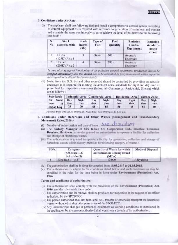
266 Annexure-IV 2
267 Annexure-IV 3
268 Annexure-IV 4
269 Annexure-V LIST OF NEARBY INDUSTRIES OF ROORKEE TERMINAL SL NO. INDUSTRY PLOT NO. AREA DIRECTION 1 HPCL, Bulk Oil Depot, Roorkee C-2, m 2. SE 2 BPCL, LPG Bottling Plant Roorkee A-3, m 2. SE 3 RANA Steels A-1/1, A-1/ m 2., m 2. NE 4 Cavendish Industries Limited, Laksar acres or m km SE from site 5 Gold Plus Glass Industry Limited acres or m m, SW from site 1
270 Annexure-V 2
 REGD./AD SEIAA-EC-147/Il/ 3 2.lj 11 May. 2011 Sub.: Construction of Dne Additional MS {Petrol) Tank of Dia 18 meter, ht.")
271 Annexure-VI To. STATE LEVEL ENVIRONMENT IMPACT ASSESSMENT AUTHORITY E-118, Nehru Colony, Haridwar Road, Oehradun (Uttarakhand} M/S Indian Oil Corporation Ltd. Plot NO. - 4-A. UPSIOC Industrial Area landhora Roorkee Distt Haridwar (Uttarakhand) REGD./AD SEIAA-EC-147/Il/ 3 2.lj 11 May Sub.: Construction of Dne Additional MS {Petrol) Tank of Dia 18 meter, ht. 13 meter arid Capacity 2984 KL by M/s Indian Oil Corporation., for Environmental Clearance. reg. Kindly refer to your application no. RKEIUEPPCB dated seeking environmental clearance under the Environmental Impact Assessment Notification I. The State level Expert Appraisal Committee (SEAC) has examined the proposal. It is noted that the proposal is for manufacturing construction of one additional MS (Petrol) tank of dia. 18 meter. ht. 13 meter and capacity of 2984 Kl. at UPSIDC industrial area Landhora Roorkee District Haridwar Uttrakhand. The process proposed by the project proponent is storage of petrol for handling of additional market requirement. The total project cost of unit is Rs. 257 Lacs. The unit is proposed to employ 51 man powers. Total area of the unit is Sq. meter. The total water requirement of the unit is 02 KLO. which will be sourced from the existing two number of bore wells.. No wastewater is proposed to be discharged outside the plant premises. The proponent has provided OG sets of 2x250 KVAixl25 KVA capacity for power back up. which whi be equipped with the acoustic enclosure. The project proponent also submitted layout plan of area indicating 33% area for green belt development. The proponent has proposed to dispose the hazardous waste in the tune of 4.5 to 5.0 MT semi solid oily sludge through M/ Bharat Oil fi Waste Management. The proponent has informed that the project site is 23 KM from the interstate boundary and District Magistrate Haridwar has granted NOC for setting up POl depot at Roorkee vide letter no dated May The project activity is listed in Sr. No.8 (b) of schedule of the Environment Impact Assessment Notification the committee examined the proposal and information submitted by the project proponent and observed that the project is located in notified industrial area of Uttarakhand. 3. Based on the information submitted by project proponent and the recommendation of the State Level r ~ ' I" 't nra"',..,.. t!.,. 'ut'.. '"'"' '' up~:wt HppraJSBJ LJOmmJ tee \tltlu,,, Uli:.Jtate tn\'tronmt:rr 1mpact itssessment " ulurtt) \iltth~j hereby accords "Environment Clearance" for proposed activities subject to compliance of the following conditions. A SPECIFIC CONDITIONS: I. Water requirement shall not exceed 2Kl. which shall be sourced from the existing bore well. 2. The oily sludge generated from various sources shall be collected and disposed through registered recyclers duly authorised by competent authority under hazardous waste management rules.. 3. All waste residues and Oily sludge etc. shall be sent to TSDF for disposal. Hazardous chemicals shall be stored in tanks in tank farms. drums. carb11ys etc. Flame arrestet s shall be provided on tank farm. Solvent transfer shall be by pumps. MIS Rasna Pvt. Ltd., Selaqui, Dehradun 1 Page 1 of4
 Rules 2008. 5.")
272 Annexure-VI 4. The unit shall strictly comply the provisions of the Manufacture. Storage and Import of Hazardous Chemicals Rules.IS8S and the Hazardous Wastes (Management. Handling and Trans boundary Movement) Rules The project proponent shall prepare and keep up to date On Site Emergency Plan duly approved by the competent authority and shall submit to this office periodically. 6. The project proponent shall take appropriates steps to inform persons outside the site either directly or through district emergency authority who are likely to be in an area which may be affected by major accident about the nature of the major accident hazards and safety measures and do's and don't which should be adopted in the event of major accident. 1. One-third of the total area of the project shall be developed as green belt with suitable sp~cies of plants as per the CPCB guidelines. 8. The project proponent shall obtain 'Consent to Establish' and 'Consent to Operate' from the UEPPCB. 8. The project proponent shall obtain the necessary permission/noc from the respective regulatory authorities prior to operation of the unit. 10. The project proponent shall submit the compliance report of Environment Clearance in every six months to the Authority. II. The project proponent shall obtain permission from the Central Ground Water Board for extraction of ground water. 12. The 'Environmental Clearance' is valid for installation of one additional MS Tank (2984Kl) for storage of petrol only. B. GENERAL CDNDITIDNS: I. The project authorities shall strictly adhere to the stipulations made by the UEPPCB. 2. No further modifications or expansion shall be carried out without prior approval of the Competent Authority. In case of deviations or alterations in the project proposal from those submitted to this Authority for clearance. a fresh reference shall be made to the Authority to assess the adequacy of conditions imposed and to add additional environmental protection measures required. if any. 3. At no time. the emissions shall exceed the prescribed limits. In the event of failure of any pollution control system adopted by the unit. the unit shall be immediately put out of operation and shall not be restarted until the desired efficiency has been achieved. 4. The gaseous emissions (SOx. NOx. CO. VOC and HC) and particulate matter along with RSPM levels from various process units shall conform to the standards prescribed by the concerned authorities from time to time. At no time. the emission levels shall go beyond the stipulated standards. In the event of failure of pollution control system adopted by the unit. the respective unit shall not be restarted until the control measures are rectified to achieve the desired efficiency. 5. The!o::ations of ambient air quality monitoring stations shall be reviewed in consultation with the UEPPCB and additional stations shall be installed. if required. in the downwind direction as well as where maximum ground level concentrations are anticipated. 6. The stacks of appropriate height as per the Central Pollution Control Board guidelines shall be provided to control the emissions from various vents. 1. All liquid raw materials shall be stored in storage tanks and drums. Closed handling systems for chemicals and solvents will be provided. Magnetic seals shall be provided for pumps/ agitators for reactors for reduction of fugitive emissions. Solvent traps shall be installed wherever necessary. Reactor generating solvent vapours will be connected to condensers with receivers. B. All venting equipment shall h~ve vapour recovery system. All the pumps and other equipments where there is a likelihood of HC leakages shall be provided with Leak Oefectinn iilld Repair (LOAR) system and LEL indicators and ~ MIS Rasna Pvt. Lid., Selaqui, Dehradun I i I 2 Page 2 of4
 program for quantification and ~:ontrol of fugitive emissions. The dete~:tors sensitivity shall be in ppm levels. S.")
273 Annexure-VI lfydrocarbon detectors. Provision for immediate isolation of such equipment. in case of a leakage shall also be made. The company shall provide a well defined Leak Detection and Repair (LOAR) program for quantification and ~:ontrol of fugitive emissions. The dete~:tors sensitivity shall be in ppm levels. S. The ~:ompany shall undertake following waste minimization measures. Metering and ~:ontrol of quantities of active ingredients to minimize waste. Reuse of by-produ~:ts from the pro~:ess as raw materials or as raw material substitutes in other pro~:esses. Use of automated filling to minimize spillage. Use of "Close Feed" system into bat~:h rea~:tors. Venting equipment through vapour re~:overy system. Use of high pressure hoses for equipment deaning to redu~:e wastewater generation. 10. Fugitive emissions in the work zone environment. produ~:t and raw materials storage area shall be regularly monitored. The emissions shall~:onform to the limits imposed by the UEPPCB/Central Pollution Control Board. Oust I powder from the formulation pro~:ess shall be collected by dust extra~:tor. II. The proje~:t authorities shall strictly ~:omply with the rules and guidelines under Manufacture. Storage and Import of Hazardous Chemi~:als Rules as amended in D~:tober. ISS4 and January and Hazardous Waste (Management. Handling and Trans boundary) Rules as amended from time to time. Authorization from the UEPPCB shall be obtained for ~:olle~:tion. treatment. storage. and disposal of hazardous wastes. All Transportation of Hazardous Chemicals shall be as per the MV ACT The proje~:t proponent shall provide necessary arrangement for segregation of solid wastes. Biodegradable wastes shall be disposed through composting and non-biodegradable waste shall be disposed through end users. 13. The overall noise levels in and around the plant area shall be kept well within the standards by providing noise ~:ontrol measures induding a~:ousti1: hoods. silencers. endosures et1:. on all sources of noise generation. The ambient noise levels shall~:onform to the standards pres~:ribed under Environment(Prote~:tion) Act Rules viz. 75 db(a) (day time) and 70 db(a) (night time). 14. Occupational health surveillance of the workers shall be carried out on a regular basis and records shall be maintained as per the Fa~:tories A~:t. 15. Training shall be imparted to all employees on safety and health aspe~:ts of chemicals handling. Pre-employment and routine perii:jdi~:al medi~:al examinations for all employees shall be undertaken on regular basis. IS. The Company shall harvest surfa~:e as well as rainwater from the rooftops of the buildings proposed in the expansion proje~:t and storm water drains to re~:harge the ground water and use the same water for the various activities of the proje~:t to ~:onserve fresh water. 17. The proje~:t proponent shall also ~:omply with all the environmental prote~:tion measures and safeguards proposed in the EIA/EMP report. All the re~:ommendations made in respect of environmental management and risk mitigation measures relating to the project shall be implemented. 18. The company will undertake all relevant measures for improving the socioe~:onomi~: ~:onditions of the surrounding area. CSR a~:tivities will be undertaken by involving lo~:al villages and administration.. IS. The ~:ompany shall undertake eco-developmental measures induding community welfare measures in the proje~:t area for the overall improvement of the environment. 20. A separate Environmental Management Cell equipped with full fledged laboratory fal:ilities shall be set up to carry out the Environmental Management and Monitoring functions. 21. The Authority may revoke/ suspend the environment Clearan~:e if implementation of any of the ~:ondition is not s ati sfa~:to ry and also the Authority reserves the right to stipulate addit~onal condition(s). if found ne~:essary. The MIS Rasna Pvt. Ltd., Selaqui, Dehradun \ 3 Page 3 of 4
 Act 1974. the Air (Prevention and Control of Pollution) Act 1981. the Environment (Protection) Act 1988.")
274 Annexure-VI Project proponent in a time bound manner will implement these conditions. 22. The stipulated conditions will be enforce. inter alia under the provisions of the Water (Prevention and Control of Pollution) Act the Air (Prevention and Control of Pollution) Act the Environment (Protection) Act Hazardous Waste (Management. Handling fi Trans boundary} Rules 2008 and the Manufacture. Use fi Import of Hazardous Chemical Rules 1989 and the Public Liability Insurance Act along with their amendment and rules. 23. This Environment Clearance is valid for five year from the date of issue of Environment Clearance or commissioning of project. whichever is earlier. The project proponent shall inform to the Authority as well as UEPPCB. the date of start of the project and its completion. 24. The implementation of the project vis-a-vis environmental act shall be monitored by the team of the Authority. A six monthly compliance status report shall be submitted to Authority and shall be posted on the website of the company. 25. The Project proponent shall inform the public that the project has been accorded the environment clearance by the Authority. This shall be advertise within seven days from the date of issue of clearance letter. at least in two local news paper that are widely circulated in the region of which one shall be in the verna ~.; u! a r language of t~e locality concerned and a copy of the same shall be forwarded to SEIAA and UEPPCB. Yours faith~ ~,.S \ (Or. Ajay Gairola) Member Secretary Copy to following for kind information please: I. Secretary. Environment and Forests. Govt of Uttarakhand. Dehradun. 2. Chairman. State Level Environment Impact Assessment Authority." Govt. of Uttarakhand. Oehradun. 3. Chairman. State Level Expert Appraisal Committee. Uttarakhand. 4. Principal Chief Conservator of Forests. Uttarakhand. 87. Rajpur Road. Dehradun. Uttarakhand. 5. Director. la Division. Ministry of Environment fi Forest. Paryavaran Bhawan. CGO Complex. Lodhi Road. New Delhi S. Member Secretary. Uttarakhand Environment Protection and Pollution Control Board. E-115. Nehru Colony. Dehradun. c (. \. / Member Secretary MIS Rasna Pvt. Ltd., Selaqui, Dchradun 4 Page 4 of4
275 Annexure-VI 5
276 Annexure-VII 1

277 Annexure-VII 2

278 Annexure-VII 3

279 Annexure-VII 4

280 Annexure-VII 5


281 Annexure-VII 6

282 Annexure-VII 7


283 Annexure-VII 8

284 Annexure-VII 9

285 Annexure-VII 10
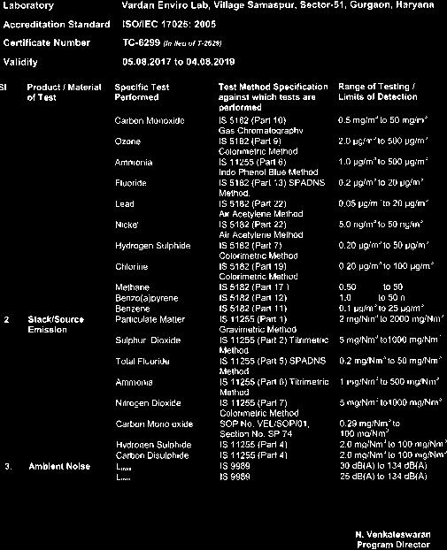

286 Annexure-VII 11

287 Annexure-VII 12
288 Annexure-VIII 1
289 Annexure-VIII 2
290 Annexure-VIII 3
291 Annexure-VIII 4
292 Annexure-VIII 5
293 Annexure-VIII 6
294 Annexure-VIII 7
295 Annexure-VIII 8
296 Annexure-VIII 9
297 Annexure-VIII 10
298 Annexure-VIII 11
299 Annexure-VIII 12
300 Annexure-VIII 13
301 Annexure-VIII 14
302 Annexure-VIII 15
303 Annexure-VIII 16
304 Annexure-VIII 17
305 Annexure-VIII 18
306 Annexure-VIII 19
307 Annexure-VIII 20
308 Annexure-VIII 21
309 Annexure-VIII 22
310 Annexure-VIII 23
311 Annexure-VIII 24
312 Annexure-VIII 25
313 Annexure-VIII 26
314 Annexure-VIII 27
315 Annexure-VIII 28

316 Annexure-VIII 29
317 Annexure-VIII 30
318 Annexure-VIII 31
319 Annexure-VIII 32

320 Annexure-VIII 33
321 Annexure-VIII 34

322 Annexure-VIII 35
323 Annexure-VIII 36
324 Annexure-VIII 37
325 Annexure-VIII 38

326 Annexure-VIII 39
327 Annexure-VIII 40

328 Annexure-VIII 41
329 Annexure-VIII 42

330 Annexure-VIII 43
331 Annexure-VIII 44

332 Annexure-VIII 45
333 Annexure-VIII 46

334 Annexure-VIII 47
335 Annexure-VIII 48
336 Annexure-VIII 49
337 Annexure-VIII 50
338 Annexure-VIII 51
339 Annexure-VIII 52
340 Annexure-VIII 53
341 Annexure-VIII 54
342 Annexure-VIII 55
343 Annexure-VIII 56
344 Annexure-VIII 57
345 Annexure-VIII 58
346 Annexure-VIII 59
347 Annexure-VIII 60
348 Annexure-VIII 61
349 Annexure-VIII 62
350 Annexure-VIII 63
351 Annexure-VIII 64
352 Annexure- IX Micrometeorology Data, Roorkee for the study period: 1st Dec2017 to 28th Feb, 2018 Temperature and Relative Humidity Data for the study period: 01 Dec 2018 to 31 Dec 2018 has been shown in given below Table No. 01 Table No. 01 Temperature ( 0 C) Relative Humidity (%) Date Min. Max. Date Min. Max. Rainfall (mm) High/Low value High/Low value Page 1 of 6


353 Annexure- IX Micrometeorology Data, Roorkee for the study period: 1st Dec2017 to 28th Feb, Temperature profile form 1st Dec, 2017 to 31st Dec, Temp. degc Min. Max. 0 Date Figure 1: Temperature profile for the month December Relative Humidity % profile form 1st Dec, 2017 to 31st Dec, 2017 RH % Min. Max Date Figure 2: Humidity profile for the month December 2017 Page 2 of 6
354 Annexure- IX Micrometeorology Data, Roorkee for the study period: 1st Dec2017 to 28th Feb, 2018 Temperature and Relative Humidity Data for the study period: 01 JAN 2018 to 31 JAN 2018 has been shown in given below Table No. 2 Table No. 02 Temperature ( 0 C) Relative Humidity (%) Date Min. Max. Date Min. Max. Rainfall (mm) High/Low value High/Low value Page 3 of 6
355 Annexure- IX Micrometeorology Data, Roorkee for the study period: 1st Dec2017 to 28th Feb, Temperature profile form 01 JAN 2018 to 31 JAN Temp. degc Min. Max. 0 Date Figure 1: Temperature profile for the month Janaury, 2018 RH % Relative Humidity % profile form 01 JAN 2018 to 31 JAN 2018 Min. Max. Date Figure 4: Humidity profile for the month January, 2018 Page 4 of 6
356 Annexure- IX Micrometeorology Data, Roorkee for the study period: 1st Dec2017 to 28th Feb, 2018 Temperature and Relative Humidity Data for the study period: 01 FEB 2018 to 28 FEB 2018 has been shown in given below Table No.3 Table No.3 Temperature ( 0 C) Relative Humidity (%) Date Min. Max. Date Min. Max. Rainfall (mm) High/Low value High/Low value Page 5 of 6

357 Annexure- IX Micrometeorology Data, Roorkee for the study period: 1st Dec2017 to 28th Feb, Temperature profile form 01 FEB 2018 to 28 FEB 2018 Temp. degc Min. Max. Date Figure 5: Temperature profile for the month February, 2018 RH in % Relative Humidity% form 01 FEB 2018 to 28 FEB Date Min. Max. Figure 6: Humidity profile for the month February, 2018 Page 6 of 6
358 Cummins Field Service Report *SINGLE POINT CONTACT(SPC) Contact: , Name of the Dealership : Jakson Enterprises Pvt Ltd Location :Haridwar FSR No: RS/171 Date : Customer Name : INDIAN OIL CORPORATION LTD Address: Landhora Person Contacted : MR. Divya chauhan Designation : Assistant manager Id : divyac@indianoil.in Mobile No : SRN : SR-JE-HA Type of Service AMC/SPSC/O and M ESN : Gen/Equp.Model : Failed at Hrs : Cumulative Hrs : 6099 GSN : Equp. Sr. No : Avg. Monthly Runninng Hrs: Last B check Hrs : 5933 Eng Model : ENGINE.NT OEM : Powerica Digital Fail Code(s) : Global Fail Code(Three level): DG Set : Manual *Controller Type : ECPG Brand and Grade of Lube Oil used:vcl15w40 Engine Performance Parameters Units Type of Coolant Used:DCA2 Low Idle RPM Lube Oil Pressure Coolant ConCentratation Level : Coolant ph : High Idle RPM 1540 Lube Oil Pressure 3.5 bar Date Customer Complaint Full Load RPM Lube Oil Pressure (dd/mm/yyyy) Time Coolant Temp HT58 O C Lube Oil Temp O C Failure Date & Time 11/06/ :58 LT O C Battery Complaint Received on 11/06/ :58 Battery S.No 1 Model Make Volt OCV Service Required Date & Time 11/06/ :59 2 Cummins 26 Service Representative Deputed on 11/06/ :14 Parameters of Generator Set Parameters for other Applications Service Representative Reached at site 11/06/ : Annexure-X Voltage(AC) V Drilling Speed : RPM Diagnosis Completed on 11/06/ :37 Current(AC) Amp Stall Speed : RPM Required Material Received On Frequency : 51 HZ Gear Speed : RPM Commissioning Date & Time 11/06/ :37 Load : Power Factor Problem Pertains to : Customer Complaint : AMC VISIT. Inspection / Observation & Work Done in Brief :Checked engine lube oil level, coolent level found OK. checked battery voltage found OK. checked fan belt tension found OK. started the dg set and checked parameters found with in limit.. Problem Resolution / Solution : Carried out amc visit. Recommendation / Suggestion(Use overleaf format for component requirements) and any other Discrepanies Observed: Service Representative's Name :Mr Rajnish Sharma Mobile No: ID No: HAC Pro ID No. : Date : Sign: Distribution:Customer / AO /Dealer Problem Status:Close Responsibility(If status is open) : Customer's Remarks(For escalation, use hierarchy given overleaf) : Customer's Experience : Customer's Name:INDIAN OIL CORPORATION LTD Sign.with Seal: Date : Our Goal:Zero Engine Down 1
359 Cummins Field Service Report *SINGLE POINT CONTACT(SPC) Contact: , Name of the Dealership : Jakson Enterprises Pvt Ltd Location :Haridwar FSR No: RD/171 Date : Customer Name : INDIAN OIL CORPORATION LTD Address: Landhora Person Contacted : MR. Divya chauhan Designation : Assistant manager Id : divyac@indianoil.in Mobile No : SRN : SR-JE-HA Type of Service AMC/SPSC/O and M ESN : Gen/Equp.Model : Failed at Hrs : Cumulative Hrs : 4720 GSN : Equp. Sr. No : Avg. Monthly Runninng Hrs: Last B check Hrs : 4560 Eng Model : ENGINE.NT OEM : Powerica Digital Fail Code(s) : Global Fail Code(Three level): DG Set : Manual *Controller Type : ECPG Brand and Grade of Lube Oil used:vcl15w40 Engine Performance Parameters Units Type of Coolant Used: Low Idle RPM Lube Oil Pressure Coolant ConCentratation Level : Coolant ph : High Idle RPM 1530 Lube Oil Pressure 3.5 bar Date Customer Complaint Full Load RPM Lube Oil Pressure (dd/mm/yyyy) Time Coolant Temp HT57 O C Lube Oil Temp O C Failure Date & Time 11/06/ :52 LT O C Battery Complaint Received on 11/06/ :52 Battery S.No 1 Model Make Volt OCV Service Required Date & Time 11/06/ :53 2 Cummins 26 Service Representative Deputed on 11/06/ :14 Parameters of Generator Set Parameters for other Applications Service Representative Reached at site 11/06/ : Annexure-X Voltage(AC) V Drilling Speed : RPM Diagnosis Completed on 11/06/ :45 Current(AC) Amp Stall Speed : RPM Required Material Received On Frequency : 51 HZ Gear Speed : RPM Commissioning Date & Time 11/06/ :45 Load : Power Factor Problem Pertains to : Customer Complaint : AMC VISIT. Inspection / Observation & Work Done in Brief :Checked engine lube oil level, coolent level found OK. checked battery voltage found OK. checked fan belt tension found OK. started the dg set and checked parameters found with in limit. Problem Resolution / Solution : Carried out amc visit. Recommendation / Suggestion(Use overleaf format for component requirements) and any other Discrepanies Observed: Service Representative's Name :Mr Rajnish Sharma Mobile No: ID No: HAC Pro ID No. : Date : Sign: Distribution:Customer / AO /Dealer Problem Status:Close Responsibility(If status is open) : Customer's Remarks(For escalation, use hierarchy given overleaf) : Customer's Experience : Customer's Name:INDIAN OIL CORPORATION LTD Sign.with Seal: Date : Our Goal:Zero Engine Down 2
360 Cummins Field Service Report Annexure-X *SINGLE POINT CONTACT(SPC) Contact: , Name of the Dealership : Jakson Enterprises Pvt Ltd Location :Haridwar FSR No: RS154 Date : Customer Name : INDIAN OIL CORPORATION LTD Address: Roorkee Person Contacted : MR. DIVYA CHAUHAN Designation : Manager Id : divyac@indianoil.in Mobile No : SRN : SR-JE-HA Type of Service AMC/SPSC/O and M ESN : Gen/Equp.Model : Failed at Hrs : Cumulative Hrs : 172 GSN : Equp. Sr. No : Avg. Monthly Runninng Hrs: Last B check Hrs : 172 Eng Model : ENGINE.KTA-19- F3-I OEM : Jakson Digital Fail Code(s) : Global Fail Code(Three level): DG Set : AMF *Controller Type : ECP Brand and Grade of Lube Oil used:servo 15w40 Engine Performance Parameters Units Type of Coolant Used: Low Idle RPM Lube Oil Pressure Coolant ConCentratation Level : Coolant ph : High Idle RPM 1530 Lube Oil Pressure 6.0 kg/cm2 Date Customer Complaint Full Load RPM Lube Oil Pressure (dd/mm/yyyy) Time Coolant Temp HT64 O C Lube Oil Temp O C Failure Date & Time 28/05/ :21 LT O C Battery Complaint Received on 28/05/ :21 Battery S.No 1 Model Make Volt OCV Service Required Date & Time 28/05/ : Service Representative Deputed on 28/05/ :34 Parameters of Generator Set Parameters for other Applications Service Representative Reached at site 28/05/ :51 Voltage(AC) V Drilling Speed : RPM Diagnosis Completed on 28/05/ :51 Current(AC) Amp Stall Speed : RPM Required Material Received On Frequency : Gear Speed : RPM Commissioning Date & Time 28/05/ :51 Load : Power Factor Problem Pertains to : Customer Complaint : AMC VISIT... Inspection / Observation & Work Done in Brief :Checked engine lube oil level, coolent level found OK. checked battery voltage found OK. checked belt tension found OK.started the fire engine and checked parameters found with in limit. Problem Resolution / Solution : Carried out amc visit. Recommendation / Suggestion(Use overleaf format for component requirements) and any other Discrepanies Observed: Service Representative's Name :Mr Rajnish Sharma Mobile No: ID No: HAC Pro ID No. : Date : Sign: Distribution:Customer / AO /Dealer Problem Status:Close Responsibility(If status is open) : Customer's Remarks(For escalation, use hierarchy given overleaf) : Customer's Experience : Customer's Name:INDIAN OIL CORPORATION LTD Sign.with Seal: Date : Our Goal:Zero Engine Down 3
361 Cummins Field Service Report Annexure-X *SINGLE POINT CONTACT(SPC) Contact: , Name of the Dealership : Jakson Enterprises Pvt Ltd Location :Haridwar FSR No: RS/155 Date : Customer Name : INDIAN OIL CORPORATION LTD Address: Landhora Person Contacted : MR.D.chauhan Designation : Maintenance Id : divyac@indianoil.in Mobile No : SRN : SR-JE-HA Type of Service AMC/SPSC/O and M ESN : Gen/Equp.Model : Failed at Hrs : Cumulative Hrs : 2366 GSN : Equp. Sr. No : Avg. Monthly Runninng Hrs: Last B check Hrs : 2341 Eng Model : ENGINE.KTA-19- F3-I OEM : Digital Fail Code(s) : Global Fail Code(Three level): DG Set : *Controller Type : ECP Brand and Grade of Lube Oil used: Engine Performance Parameters Units Type of Coolant Used: Low Idle RPM Lube Oil Pressure Coolant ConCentratation Level : Coolant ph : High Idle RPM 1530 Lube Oil Pressure 6.3 kg/cm2 Date Customer Complaint Full Load RPM Lube Oil Pressure (dd/mm/yyyy) Time Coolant Temp HT65 O C Lube Oil Temp O C Failure Date & Time 28/05/ :19 LT O C Battery Complaint Received on 28/05/ :19 Battery S.No 1 Model Make Volt OCV Service Required Date & Time 28/05/ : Service Representative Deputed on 28/05/ :34 Parameters of Generator Set Parameters for other Applications Service Representative Reached at site 28/05/ :16 Voltage(AC) V Drilling Speed : RPM Diagnosis Completed on 28/05/ :16 Current(AC) Amp Stall Speed : RPM Required Material Received On Frequency : Gear Speed : RPM Commissioning Date & Time 28/05/ :16 Load : Power Factor Problem Pertains to : Customer Complaint : AMC VISIT... Inspection / Observation & Work Done in Brief :Checked engine lube oil level, coolent level found OK. checked battery voltage found OK. checked belt tension found OK. started the fire engine and checked parameters found with in limit. Problem Resolution / Solution : Carried out amc visit. Recommendation / Suggestion(Use overleaf format for component requirements) and any other Discrepanies Observed: Service Representative's Name :Mr Rajnish Sharma Mobile No: ID No: HAC Pro ID No. : Date : Sign: Distribution:Customer / AO /Dealer Problem Status:Close Responsibility(If status is open) : Customer's Remarks(For escalation, use hierarchy given overleaf) : Customer's Experience : Customer's Name:INDIAN OIL CORPORATION LTD Sign.with Seal: Date : Our Goal:Zero Engine Down 4
362 Cummins Field Service Report Annexure-X *SINGLE POINT CONTACT(SPC) Contact: , Name of the Dealership : Jakson Enterprises Pvt Ltd Location :Haridwar FSR No: RS/156 Date : Customer Name : INDIAN OIL CORPORATION LTD Address: Landhora Person Contacted : MR.D.chauhan Designation : Manager Id : divyac@indianoil.in Mobile No : SRN : SR-JE-HA Type of Service AMC/SPSC/O and M ESN : Gen/Equp.Model : Failed at Hrs : Cumulative Hrs : 184 GSN : Equp. Sr. No : Avg. Monthly Runninng Hrs: Last B check Hrs : Eng Model : ENGINE.KTA-19- F3-I OEM : Digital Fail Code(s) : Global Fail Code(Three level): DG Set : *Controller Type : ECP Brand and Grade of Lube Oil used: Engine Performance Parameters Units Type of Coolant Used: Low Idle RPM Lube Oil Pressure Coolant ConCentratation Level : Coolant ph : High Idle RPM 1530 Lube Oil Pressure 6.0 kg/cm2 Date Customer Complaint Full Load RPM Lube Oil Pressure (dd/mm/yyyy) Time Coolant Temp HT65 O C Lube Oil Temp O C Failure Date & Time 28/05/ :14 LT O C Battery Complaint Received on 28/05/ :14 Battery S.No 1 Model Make Volt OCV Service Required Date & Time 28/05/ : Service Representative Deputed on 28/05/ :34 Parameters of Generator Set Parameters for other Applications Service Representative Reached at site 28/05/ :23 Voltage(AC) V Drilling Speed : RPM Diagnosis Completed on 28/05/ :23 Current(AC) Amp Stall Speed : RPM Required Material Received On Frequency : Gear Speed : RPM Commissioning Date & Time 28/05/ :23 Load : Power Factor Problem Pertains to : Customer Complaint : AMC VISIT... Inspection / Observation & Work Done in Brief :Checked engine lube oil level, coolent level found OK. checked battery voltage found OK. checked belt tension found OK. Started the fire engine and checked parameters found with in limit. Problem Resolution / Solution : Carried out amc visit. Recommendation / Suggestion(Use overleaf format for component requirements) and any other Discrepanies Observed: Service Representative's Name :Mr Rajnish Sharma Mobile No: ID No: HAC Pro ID No. : Date : Sign: Distribution:Customer / AO /Dealer Problem Status: Responsibility(If status is open) : Customer's Remarks(For escalation, use hierarchy given overleaf) : Customer's Experience : Customer's Name:INDIAN OIL CORPORATION LTD Sign.with Seal: Date : Our Goal:Zero Engine Down 5
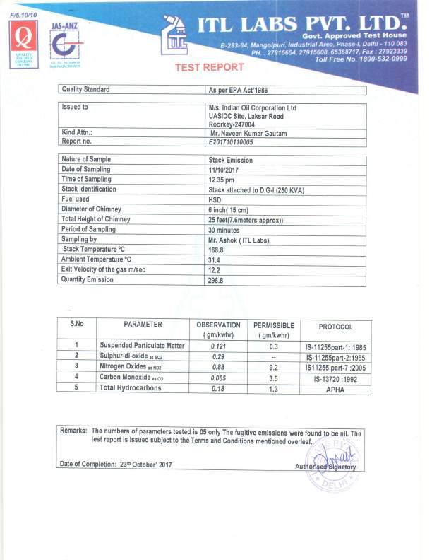
363 Annexure-XI 1

364 Annexure-XI 2

365 Annexure-XI 3

366 Annexure-XI 4

367 Annexure-XI 5

368 Annexure-XI 6

369 Annexure-XI 7
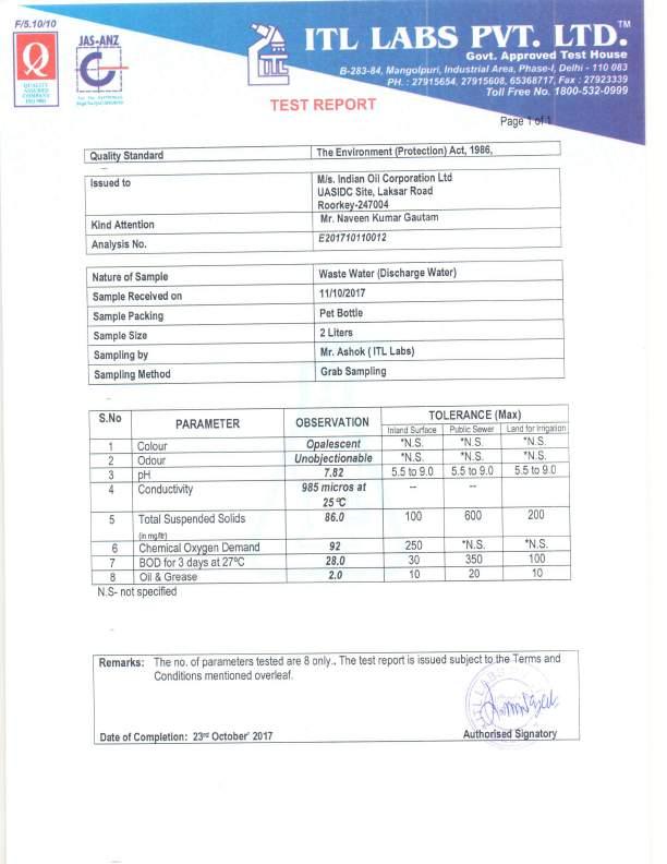
370 Annexure-XI 8

371 Annexure-XI 9
372 Annexure-XII INDIAN OIL CORPORATION LIMITED ROORKEE TOP Laboratory, ROORKEE ROORKEE TEST REPORT Material: EFFLUENT WATER -Effluent Water Reason for test: INSPECTION-EFFLUENT WATER Industry standard description: Inspection lot number: Sample drawn date: Store/Tank no.: Sample receipt date: Stock represented: L Lot release date: Note: LTRK/EFFLUENT WATER/OWS/801 Customer Tank: REVN Customer: ZC ROORKEE TOP SRL CHARACTERISTIC TEST SPECIFICATION TEST RESULTS METHOD (ASTM/IP/IS1448) LIMIT & UNIT Operation : MONITORING EFFLUENT WATER 1. Oil & Grease content IS 3025 Max mg/l 5.0 UD Code: AC -MEETS SPECIFICATION W.R.T. TESTS DONE UD description : 1. Test Report No. : LTRK/Effluent Water/OWS/801 Dt Sample drwan by : Control Room Incharge Roorkee Trmnl. 3. Reason for Testing : Oil Content in Effluent water Test results relate only to the items tested. The report shall not be reproduced except in full without the written approval of laboratory. "Computer generated document. Signature not required. " Page 1 of 1 Released by:
373 EIA-EMP Report for Construction of additional Tankages at Roorkee POL Terminal, Roorkee(Uttarakhand) of M/s Indian Oil Corporation Limited Annexure-XIII to XVIII&XXI have been extracted and uploaded as a Part of Annexure-document of Risk Analysis and DMP Document No. 2017_VI_0024_FINAL EIA Consultant- M/s Vardan Environet, D-142, Sec. 57 Gurugram, Haryana (Mob: )
374 Annexure-XIX UTTARAKHAND POWER CORPORATION LIMITED DIVISION CODE BOOK NO CONNECTION NO BILL NO EDD (R) Roorkee KNO : BILL DATE : RD C BILL MONTH : March /04/2018 M/S INDIAN OIL CORPORATION LANDHORA LANDHORA ROORKEE/HARIDWAR Pin : 0 FAX : CELL NO.* : (* To receive bill related SMS alerts, please submit latest mobile no. to division) DUE DATE 04/04/2018 DISCON.DATE 04/05/2018 RTS.CATEGORY RTS-7 LT AND HT INDUSTRY RTS-SUBCATEGORY HT INDUS. LOAD UPTO 1000KVA BILL BASIS CONTR.LOAD BILLING PERIOD CONT. OPT. : N FROM TO VOL.SUP. METER MAKE METER NO SECURITY DEPOSITED ADDN.SEC.REQUIRED MU /03/ /03/ LnT LNT READING SLOT LAST READNIG CURRENT READING NH MF UNIT CONSUMED UNIT ADJUSTED UNIT ASSESSED ACTUAL TOTAL UNIT UNIT RATE RS/UNIT AMOUNT(Rs.) MP EP OP TOTAL MAX. DEMAND BILL PARAMETERS AMOUNT(Rs) OTHER DETAILS 1. EXCESS CHARGES DUE TO MCG ACTUAL ENERGY CHARGES CONTINUOUS SUPPLY SURCHARGE FIXED/DEMAND CHARGES FOR CONTR.LOAD FIXED/DEMAND CHARGES FOR EXCESS LOAD TOTAL FIXED/DEMAND CHARGES ELECTRICITY DUTY GREEN ENERGY CESS VOLTAGE SUPPLY REBATE 0.00 VOLTAGE SUPPLY SURCHARGE 10.FCA CHARGES SOLAR SYSTEM REBATE LOW POWER FACTOR SURCHARGE 0.00 CAP. SURCHARGE 12.EXCESS OFF SEASON LOAD DENIAL OF BENFIT + SURCHARGE 13.MAINTENANCE CHARGES % EXTRA FOR RTS ADDITIONAL EC ADDITIONAL REBATE NA ADJUSTMENT FOR 0 MONTH MISC.CHARGES CURRENT BILL CURRENT LPS TOTAL DUE FOR THE MONTH AMOUNT DUE IN THE LAST BILL ARREAR ADJUSTMENT(+/-) TOTAL TOTAL PAID AMOUNT AGAINST LAST BILL NET AMOUNT PAYABLE ON OR BEFORE : 04/04/ Rs. Three Lakh Thirty Seven Thousand Five Hundred Seventy Three Only PF : 0.95 LOAD FACTOR : BILLABLE DEMAND : OPEN ACCESS ENERGY RCVD : NA LOAD UNIT : CONSUMPTION UNIT : CUMULATIVE READING KVA KVAH LAST KWH : CURRENT KWH : LAST KVAH : CURRENT KVAH : LAST MONTH LPS ARREAR : LPS ARREAR ADJUSTMENT(+/-) : 0.00 LAST PAYMENT DETAILS Rcpt.: 19/F076454, 17/03/2018, Rs LAST SIX MONTH ACTUAL CONSUMPTION Feb: 44260, Jan: 50440, Dec: 46030, Nov: 44440, Oct: 53120, Sep: MCG FOR THE YEAR : CUML. ACTUAL CONSUMPTION : CUML. BILLED CONSUMPTION : ANNUAL EXCESS UNIT ADJ.:0 AMOUNT PAYABLE ON OR BEFORE : 19/04/2018 AFTER : 19/04/2018 AFTER : 04/05/2018 (THIS BILL MAY BE PAID IN ANY BRANCH OF PNB IN UTTARAKHAND BY CASH / CHEQUE OF PNB) DISPUTED ARREAR/LPS NOT INCLUDED IN THE BILL: ARREAR : 0.00 LPS : 0.00 TOTAL : 0.00 B.C. D.A.(R) A.E.(R) Executive Engineer 1. ALL PAYMENT ARE TO BE MADE IN CASH/D.D./LOCAL CHEQUE DRAWN IN FAVOUR OF EXECUTIVE ENGINEER, EDD (R) Roorkee 2. IF CHEQUE IN ANY MONTH IS DIS-HONOURED, PAYMENT IN SUBSEQUENT MONTHS SHALL BE ACCEPTED BY CASH/D.D ONLY न टस 1
375 Annexure-XX INDIANOIL CORPORATION LTD., Roorkee Terminal FLOWCHART-ACTIVITIES & REQUIREMENT OF WATER AT EACH STAGE 15 DOMESTIC USAGE SEPTIC TANK 2 SOAK PIT 5 GROUND WATER GARDENING/ GREENBELT MAINTENANCE 10 FIRE FIGHTING SYSTEM Total Water Required: = 30 m3/day # # 1. Initial Ground Water Requirement: 30 m3/day 2. Net Ground Water Requirement = 30 m3/day - CONSIDERED FOR NOC Total Water Requirement:- 1. Industrial Water Requirement: = 10 m3/day. 2. Residential / domestic: 15 m3/day. 3. Green Belt etc: 5 m3/day 1
376 EIA-EMP Report for Construction of additional Tankages at Roorkee POL Terminal, Roorkee(Uttarakhand) of M/s Indian Oil Corporation Limited Annexure-XIII to XVIII&XXI have been extracted and uploaded as a Part of Annexure-document of Risk Analysis and DMP Document No. 2017_VI_0024_FINAL EIA Consultant- M/s Vardan Environet, D-142, Sec. 57 Gurugram, Haryana (Mob: )
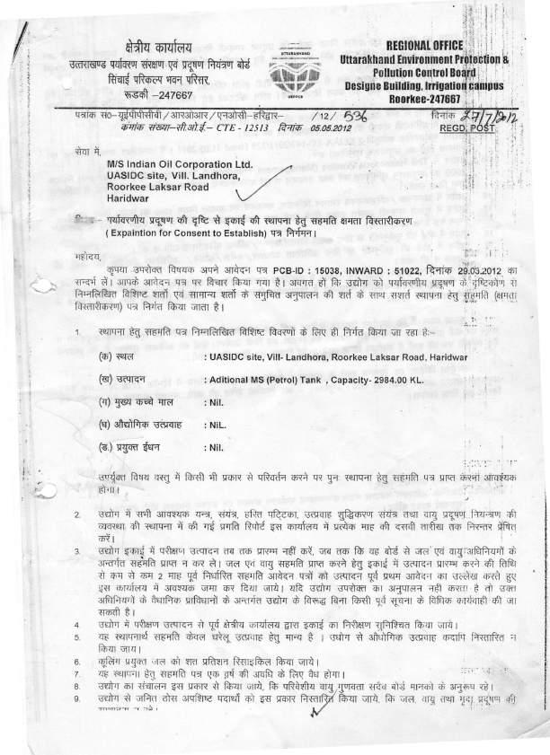
377 Annexure-XXII 1

378 Annexure-XXII 2