CONDUCTED FOR: PREPARED FOR: 18 October 2010 YPC Project No. 10GY133
|
|
|
- Griselda Burns
- 5 years ago
- Views:
Transcription
 693-7700 Fax (239) 690-0271")
1 GEOTECHNICAL EXPLORATION AND ENGINEERING SERVICES REPORT CONDUCTED FOR: Immokalee Stormwater Master Plan Implementation Immokalee, Collier County, Florida PREPARED FOR: Mr. Marc Stonehouse, P. E. Project Manager CDM World Plaza Lane, Building #51 Fort Myers, Florida October 2010 YPC Project No. 10GY133 YPC Consulting Group, PL 5701 Country Lakes Drive, Suite #3 Fort Myers, Florida Phone (239) Fax (239)
2
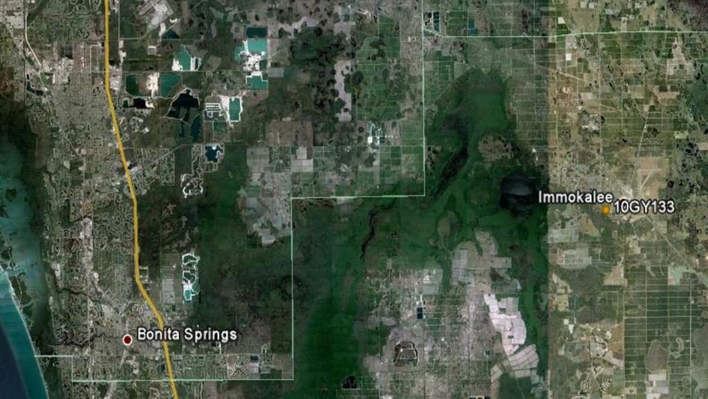
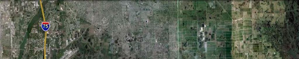
3 Mr. Marc Stonehouse, P.E. YPC Consulting Group, P.L. CDM 18 October 2010 Geotechnical Exploration and Engineering Service Report Immokalee Stormwater Master Plan Implementation Immokalee, Collier County, Florida YPC Project No. 10GY INTRODUCTION 1.1 Terms of Reference 1.2 Project Description 1.3 Purpose and Scope of Work TABLE OF CONTENTS 2.0 FIELD EXPLORATION AND LABORATORY TESTING PROGRAMS 2.1 Field Exploration Program 2.2 Laboratory Testing and Inspection Program 3.0 SITE, GROUNDWATER, AND SOIL CONDITIONS 3.1 Site Features 3.2 Groundwater Conditions 3.3 Subsurface Soil Conditions 3.4 USDA-SCS Soil Survey Information 4.0 OBSERVATIONS AND COMMENTS 5.0 HYDRAULIC CONDUCTIVITY TESTS 6.0 LIMITATIONS 7.0 ACKNOWLEDGMENT Figure 1 Project Site Location and Vicinity Map Figure 2 USDA-SCS Soil Survey Map Figure 3 Project Layout and Test Location Plan Figure 4 Boring Log Profiles (Figures 4A through 4D) i
4 Mr. Marc Stonehouse, P.E. YPC Consulting Group, P.L. CDM 18 October 2010 Geotechnical Exploration and Engineering Service Report Immokalee Stormwater Master Plan Implementation Immokalee, Collier County, Florida YPC Project No. 10GY INTRODUCTION 1.1 Terms of Reference YPC Consulting Group, P.L. (YPC) was retained by the Client to provide geotechnical exploration and engineering services for the Immokalee Stormwater Master Plan Implementation project located on various streets in downtown Immokalee, Collier County, Florida (hereafter referred to as the "project site"). Please refer to Figure 1 for a Project Site Location and Vicinity Map. These services were performed in general accordance with the CDM-YPC Professional Services Subcontractor Agreement dated 9 September Project Description YPC understands that the overall project will consist of the design of stormwater improvements for downtown Immokalee. The improvements are planned to include the construction of a retention pond with a plan area of approximately 5-acres, as well at the installation of exfiltration trenches, stormwater drainage structures, and associated drainage conveyance pipes. Geotechnical engineering and exploration services were performed to assist the Client in the design phase of the project. In coordination with the Client, a total of twenty-eight (28) shallow boring locations were selected along approximately 14,000 lineal feet of pipeline to be installed. The general layout of the test boring locations was determined from a 30% Plan Submittal set dated August 2010 that shows the downtown Immokalee stormwater improvement design concept. The 30% Plan Submittal also provided insight as to the location of the planned retention pond and nine (9) exfiltration trenches to be constructed as part of the project. 1.3 Purpose and Scope of Work The purpose of the geotechnical exploration and engineering services completed by YPC for the project was to describe, in general terms, soil and ground-water conditions encountered at the project site. To achieve this purpose, the scope of services has included the elements listed below. exploring subsurface soil and groundwater conditions by advancing twentyeight (28) Standard Penetration Test (SPT) borings along the proposed pipeline alignment to depths of approximately 10 ft below the existing ground surface (egs); 1
5 Mr. Marc Stonehouse, P.E. YPC Consulting Group, P.L. CDM 18 October 2010 Geotechnical Exploration and Engineering Service Report Immokalee Stormwater Master Plan Implementation Immokalee, Collier County, Florida YPC Project No. 10GY133 exploring subsurface soil and groundwater conditions by advancing three (3) SPT borings within the proposed 5-acre retention pond to depths of approximately 35 ft below the egs; performing nine (9) hydraulic conductivity tests near the proposed exfiltration trench areas, per SFWMD guidelines; obtaining representative soil and rock samples from the SPT borings; grouting the SPT borings in general accordance with regulatory requirements; evaluating generalized boring data as well as groundwater conditions; performing visual inspection of all soil samples and laboratory tests on selected samples for soil classification purposes; and, providing observations and comments for use by the Client in planning for the project. 2.0 FIELD EXPLORATION AND LABORATORY TESTING PROGRAMS 2.1 Field Exploration Program The field exploration program, consisting of the elements described in Section 1.3 above, was performed in general accordance with relevant portions of applicable testing procedures during the period from 21 September 2010 to 5 October The test borings were advanced by a drilling subcontractor, under the supervision of an YPC engineer, using a wet-rotary procedure. Representative soil samples were obtained using split-barrel sampling procedures. In this procedure, a 2-in. outer-diameter, split-barrel sampler is driven into the soil by a 140-lb hammer with a free-fall of 30-in. The number of blows required to drive the sampler through a 12-in. interval is termed the Standard Penetration Resistance, or "N", value, and is indicated for each sample on the boring logs. The "N" value is an indication of the relative density of granular soils in-situ. Soil samples obtained during the field exploration program were sealed immediately in the field and brought to YPC s laboratory for further examination and testing. The test boring locations were staked in the field by YPC engineers at locations accessible to a truckmounted drill rig. The test borings were advanced at the approximate locations illustrated in the Project Layout and Test Location Plan presented in Figure 3. It is noted that some 2
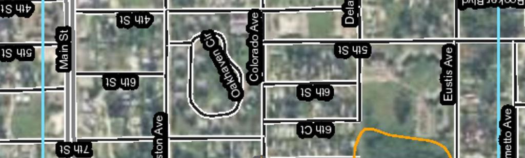
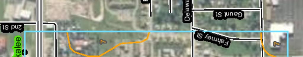
6 Mr. Marc Stonehouse, P.E. YPC Consulting Group, P.L. CDM 18 October 2010 Geotechnical Exploration and Engineering Service Report Immokalee Stormwater Master Plan Implementation Immokalee, Collier County, Florida YPC Project No. 10GY133 borings had to be offset from the originally planned locations due to on-site constraints and the presence of underground utilities, as identified under the Florida Sunshine State One- Call System. 2.2 Laboratory Testing and Inspection Program Laboratory inspection of soil samples is generally performed to assist in the classification of soils based on their mechanical and physical behavior. It is noted that the indicated boundaries between soil types are approximate, and that actual transition between soil types may be gradual. Tests were performed on selected samples retrieved for this project to determine moisture contents, percents passing a #200 U. S. standard sieve (i.e., percent silt and/or clay particles), organic contents, and soil plasticity characteristics (Atterberg limits). All soil samples were visually inspected by a geotechnical engineer and classified in general accordance with the Unified Soil Classification System (USCS). Laboratory test results are indicated on the individual boring log profiles presented in Figures 4A through 4D. 3.0 SITE, GROUNDWATER, AND SOIL CONDITIONS 3.1 Site Features The project site is located within the limits of downtown Immokalee, Florida. The main streets of the project are Boston Avenue, Colorado Avenue, and Delaware Avenue. Please refer to Figure 1 for approximate project limits. The shallow borings are located off streets and are within developed residential areas. The deeper retention pond borings are located in an undeveloped area off Eustis Avenue. The retention pond site is mostly wooded, so the borings were located at accessible areas around the perimeter of the pond site. 3.2 Groundwater Conditions At the time of the field exploration program, groundwater level was recorded at approximately 2.0 to 4.0 ft below the egs in the test borings. It is noted that any groundwater table will be subject to fluctuation due to seasonal climatic changes, tidal influences, construction and development activities, rainfall variations, surface-water runoff, extent of artificial drainage, tidal fluctuations, and other site-specific factors. Since groundwater level variations are anticipated, design drawings and specification should incorporate such possibilities and provide for dewatering, as required, during construction. 3
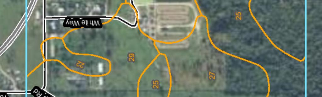
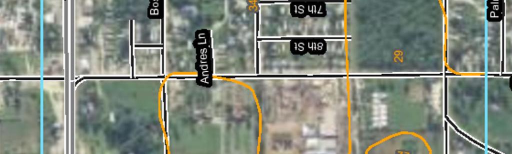
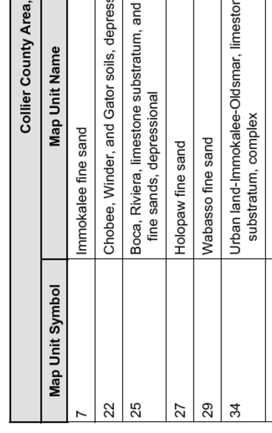
7 Mr. Marc Stonehouse, P.E. YPC Consulting Group, P.L. CDM 18 October 2010 Geotechnical Exploration and Engineering Service Report Immokalee Stormwater Master Plan Implementation Immokalee, Collier County, Florida YPC Project No. 10GY Subsurface Soil Conditions General subsurface soil conditions at the boring locations are described below (please refer to Figure 3 for the Project Layout and Test Location Plan and Figures 4A through 4D for boring log profiles). Retention Pond Borings (LB-1 through LB-3): Subsurface soils encountered in test borings LB-1 through LB-3 generally consist of poorly-graded sand (SP), poorly-graded sand with clay (SP-SC), and clayey sand (SC) from the egs to the boring termination depths 35.0 ft below the egs. Pipeline Borings (PB-1 through PB-28): Subsurface soils encountered in test borings PB-1 through PB-28 generally consist of poorly-graded sand (SP), poorly-graded sand with clay (SP-SC), poorly-graded sand with silt and organic fines (SP-SM), and clayey sand (SC) from the egs to the boring termination depths 10.0 ft below the egs. The organic fines were generally encountered in natural soils and can best be described as the organic horizon, or topsoil. 3.4 USDA-SCS Soil Survey Information Information obtained from the Soil Survey of Collier County Area [ indicates various soil mapping units within the proposed project limits, as summarized below. A USDA-SCS Soil Survey Map is included in Figure 2. SOIL NAME SHWL DEPTH SHWL (MAP UNIT SYMBOL) (ft) MONTH Immokalee fine sand (7) Jun - Sep Chobee, Winder, and Gator Soils, depressional (22) 0.0 Jun - Oct Boca, Riviers, limestone substratum, and Copeland fine sands, depressional (25) 0.0 Jun - Oct Holopaw fine sand (27) Jun - Nov Wabasso fine sand (29) Jun - Sep Urban land-immokalee-oldsmar, limestone stratum, complex (34) Jun - Sep 4
8 Mr. Marc Stonehouse, P.E. YPC Consulting Group, P.L. CDM 18 October 2010 Geotechnical Exploration and Engineering Service Report Immokalee Stormwater Master Plan Implementation Immokalee, Collier County, Florida YPC Project No. 10GY HYDRAULIC CONDUCTIVITY TESTS A total of nine (9) hydraulic conductivity tests were performed in accordance with the South Florida Water Management District Falling-Head Open-Hole test on 6 October The hydraulic conductivity test results, test locations, approximate test hole depths, and groundwater depths are summarized in the table below. TEST LOCATION (see Note 1) TEST HOLE DEPTH (ft) GROUNDWATER DEPTH (ft) HYDRAULIC CONDUCTIVITY (cfs/ft 2 ft of head) PB x 10-5 PB x 10-5 PB x 10-5 PB x 10-5 PB x 10-5 PB x 10-5 PB x 10-5 PB x 10-5 PB x 10-5 Note 1: Hydraulic conductivity tests were performed adjacent to a test boring as requested by the Client. The Test Location ID numbers in this table correspond with the number of the adjacent boring number. 5.0 OBSERVATIONS AND COMMENTS Based on current conditions and data obtained during the field exploration and visual inspection of soil samples for this project, observations and comments are presented below: Subsurface soils at retention pond area generally consist of poorly-graded sand (SP), poorly-graded sand with clay (SP-SC), and clayey sand (SC) to the boring termination depths 35 ft below the egs. Poorly-graded sand (SP) and poorly-graded sand with clay (SP-SC) can generally be used for structural fill material, if desired. Clayey sand (SC) contains more than 12 percent fines and will likely require strict moisture control to obtain 5
9 Mr. Marc Stonehouse, P.E. YPC Consulting Group, P.L. CDM 18 October 2010 Geotechnical Exploration and Engineering Service Report Immokalee Stormwater Master Plan Implementation Immokalee, Collier County, Florida YPC Project No. 10GY133 compaction. It is therefore not recommended for use as structural fill material. Subsurface soils at the pipeline alignments generally consist of poorlygraded sand (SP), poorly-graded sand with clay (SP-SC), poorly-graded sand with silt and organic fines (SP-SM), and clayey sand (SC) to the boring termination depths 10 ft below the egs. The poorly-graded sand with silt and organic fines material can generally be described as poorly-graded sand with silt mixed with the organic, or O, soil horizon. It is anticipated that the relatively small amount of O horizon materials will be mixed with generally sandy soils during excavation of pipeline trenches, and will, therefore, not significantly affect compaction efforts. The clayey sand (SC) material will likely require strict moisture control during backfill operations. Since the pipelines are planned to be within the roadway right-of-way, YPC recommends that utility backfill be compacted to at least 98% of the maximum dry density determined from ASTM D1557, entitled Standard Test Method for Laboratory Compaction Characteristics of Soils Using Modified Effort. 6.0 LIMITATIONS This geotechnical services report has been prepared for the exclusive use of the Client. No other warranty is expressed nor implied. It is noted that the information presented in this report address only soils and deposits that would normally be influenced by the proposed construction. The scope of services does not include an evaluation of deep soil or rock conditions where limestone cavities may exist due to sinkhole activity. Deep borings/ soundings, geophysical exploration, and/or resistivity surveys would be required in order to evaluate the structural condition and stability of deep soil and rock formations, and is beyond the scope of services for this project. This report has been prepared to aid in the evaluation of the property and to assist the owner and/or engineer in planning and design of this project. The scope of services is limited to the specific project and locations described herein, and the description of the project as described herein represents YPC's understanding of significant project aspects related to soil characteristics. In the event that any changes in the design or location of the structures as outlined in the report are planned, YPC must be informed so that the changes can be reviewed and the conclusions of this report modified or approved in writing. Any conclusions or recommendations made by others based on the data contained herein are not the responsibility of YPC, unless we are advised of the same in writing and given the opportunity to review those conclusions and recommendations. 6
10
11


12
13
14
15
16
17