Design and Performance Characterization of a Micro-pin-fin sco 2 Recuperator
|
|
|
- Branden Moody
- 5 years ago
- Views:
Transcription


1 Design and Performance Characterization of a Micro-pin-fin sco 2 Recuperator Cameron Naderi, Graduate Student Erfan Rasouli, Post Doctoral Scholar Vinod Narayanan*, Professor sco 2 Symposium, Pittsburg Thursday, 03/29/2018 Sponsor: grant # DE FE Microscale Thermal Energy Enhancement Laboratory
 High pressures (>200 bar) High differential pressures Corrosion Low approach temperatures between fluid")
2 Background sco 2 cycle Recompression cycle High cycle efficiency achieved only through heat recuperation Currently >20% of system cost is attributed to recuperators Design constraints/ challenges High temperatures on the hot side ( C) High pressures (>200 bar) High differential pressures Corrosion Low approach temperatures between fluid streams


 Bechtel Marine")

3 Background Compact recuperators PCHE core (Heatric; accessed 03/2018) Y. Kato, MCHE Institute, 2011 sco2 symposium 200 kw; Folded wavy fin result unit cell design Fourspring et al. (2014) Bechtel Marine and Brayton Energy Cast metal heat exchangers (Sandia, Carlson et al. 2014)

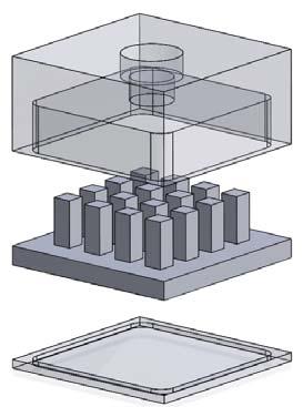
4 Goal Design a HX with enhanced heat transfer rate and lower pressure drop by Decreasing residence time by use of microscale passages Reducing pressure drop by parallelization of heat transfer paths Approach Number of recuperator unit cells connected by headers Appropriate headers for distributing cold in-flow to unit cells Appropriate headers for collecting hot exit-flow from unit cells


5 Unit cell design


6 Unit cell design Structural Outer channel; 100 bar internal pressure and 200 bar outer pressure Stainless Steel 316 yield strength ~200MPa at 400 C. Simulation max stress: 83MPa for the inner sections 129MPa for the end sections Inner channel; 200 bar internal pressure and 100 bar outer pressure


7 Unit cell design flow distribution Inlet condition: uniform velocity of ~0.126 m/s Outlet: pressure outlet peak velocities fairly uniform across the span at ~ 0.14 m/s with variation of ~0.01 m/s.


![[µm] 432.9 ± 3.9 332.0 ± 5.0 332.6 ± 4.](/docs-images/90/103873513/images/8-3.jpg "6 Average Valley Depth [µm] 179.7 ± 0.0 81.9 ± 4.")
![5 86.0 ± 2.6 Average Pin Depths [µm] 253 ± 3.](/docs-images/90/103873513/images/8-4.jpg "9 250 ± 6.7 247 ± 5.")
8 Fabrication Chemically etched shim Diffusion bonded recuperator with brazed tubes Olympus BX60 microscope image Zeiss CSM 700 confocal microscope image Etching by Great Lakes Engineering Bonding & brazing by Vacuum Process Engineering Shim Region 1 Shim Region 2 Shim Region 3 Average Plateau Height [µm] ± ± ± 4.6 Average Valley Depth [µm] ± ± ± 2.6 Average Pin Depths [µm] 253 ± ± ± 5.3 Total Average Pin Depth [µm] ± 5.3 Nominal Pin Depth 250

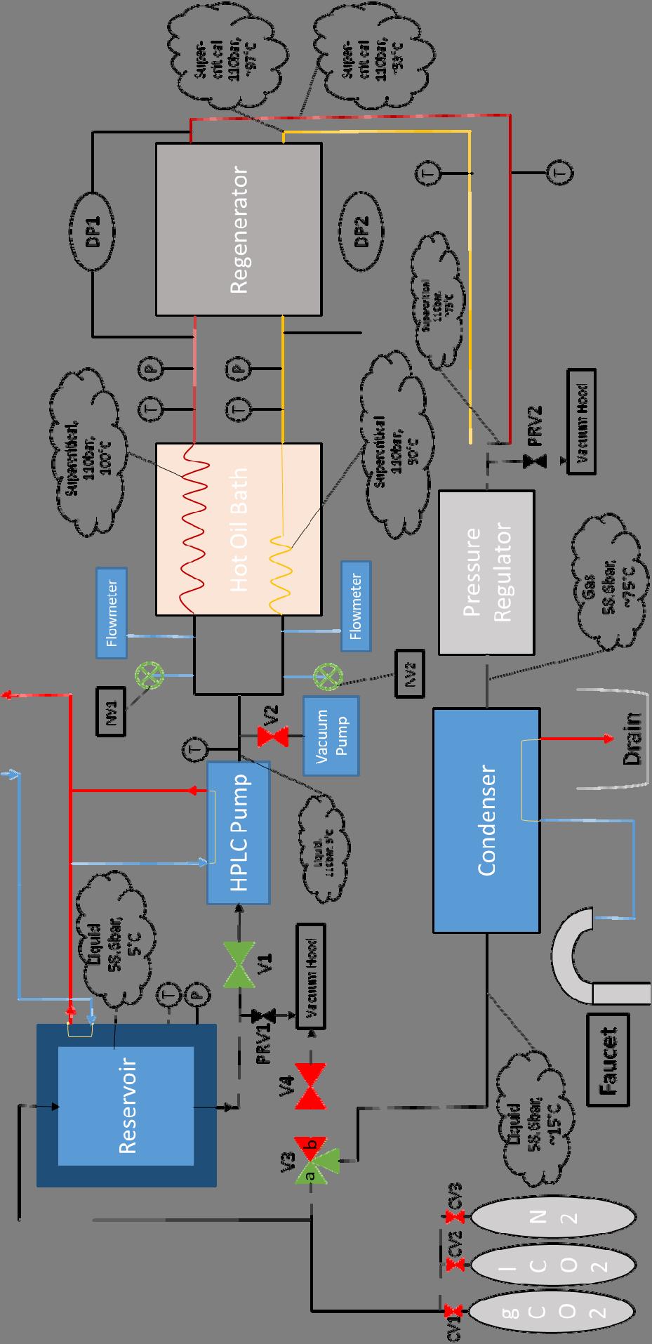
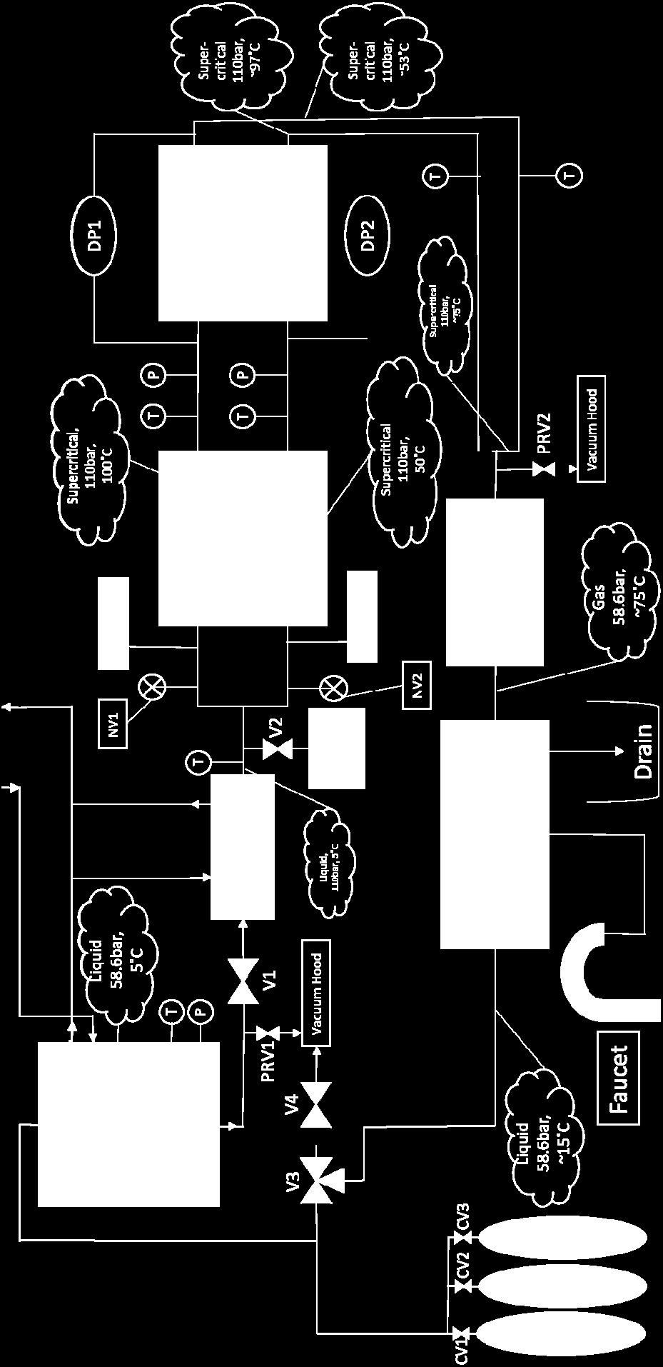
9 Experimental Facility Hot oil bath Recuperator
10 Experimental Facility Flowmeters HPLC Pump Pressure Regulator Hot Oil Bath Recuperator inlet and outlet ports CO2 Reservoir w/ Cooling Jacket Measured variable/instrument Uncertainty Micro Motion Mass Flow Meters 0.1% of flow rate Reservoir Temperature C Pump Outlet Temperature C Hot Inlet Temperature C Cold Inlet Temperature C Hot Outlet Temperature C Cold Outlet Temperature C HPLC Pump Outlet Pressure N/A Low range Differential Pressure Transducer 0.03 kpa Mid range Differential Pressure Transducer 0.04 kpa High range Differential Pressure Transducer 0.05 kpa Overall heat transfer coefficient U 1.3% Effectiveness, 0.15% Number of Transfer Units, NTU 1.2% DAQ Flowmeter Display
11 Pressure Drop results
12 Heat Transfer Results effectiveness NTU
13 Heat Transfer Results corrected effectiveness NTU
14 Heat Transfer Results
15 Heat Transfer Results
16 Example of scaling up for higher rating preliminary estimate Fixed: sco 2 mass flow rate Microchannel unit cell geometry T in, turbine = 800 C T in, comp = 40 C m dot =200kg/s Corresponds to 114 MW Higher efficiency can be obtained by increasing size and decreasing pressure drop Case 2 has 1.5 times the number of unit cells as in Case 1


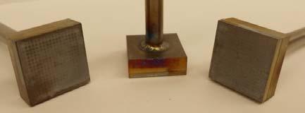
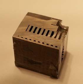
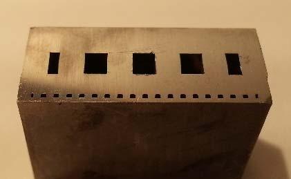
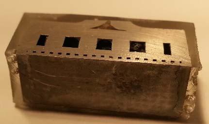
17 Diffusion Bonding of Headers to Micro pin fin regions
18 Conclusions High effectiveness recuperators are key for cycle efficiency Microchannel recuperator designed for sco 2 applications Unit cell performance characterized Preliminary diffusion bonding studies indicate that it is possible to bond headers and micro pin fin plates in a single step

19 QUESTIONS?
20 Heat loss area vs heat transfer area A_HX A_heat loss ratio 0