DRAFT STORMWATER POLLUTION PREVENTION PLAN for
|
|
|
- Grace Shaw
- 5 years ago
- Views:
Transcription


1
2 DRAFT STORMWATER POLLUTION PREVENTION PLAN for North Area Streams Levee Accreditation Program Robla Creek Woodland Mitigation and Enhancement Project RISK LEVEL 1 Legally Responsible Person (LRP): Sacramento Area Flood Control Agency th Street, 7 th Floor Sacramento, CA Contact: Pete Ghelfi (916) Prepared for: Sacramento Area Flood Control Agency th Street, 7 th Floor Sacramento, CA Contact: Pete Ghelfi (916) Project Address: Along Robla Creek, Rio Linda, CA SWPPP Prepared by: WSP 2150 River Plaza Drive Sacramento, CA Contact: Jim Lorenzen, QSD/QSP #00629 (916) SWPPP Preparation Date: June 29, 2017 Estimated Project Dates: Start of Construction September 1, 2017 Complete Site Stabilization November 30, 2018
3 This page intentionally left blank.
4 Table of Contents Section 1 SWPPP Requirements Introduction Permit Registration Documents SWPPP Availability and Implementation SWPPP Amendments Retention of Records Required Non-Compliance Reporting Annual Report Changes to Permit Coverage Notice of Termination Section 2 Project Information Site and Project Site Descriptions General Site Description Hydrology and Water Quality Project Description Developed Site Condition Permits and Governing Documents Stormwater Run-On and run-off Findings of the Construction SiteS Sediment and Receiving Water Risk Determination Construction Schedule Potential Construction Activity and Pollutant Sources Identification of Non-Stormwater Discharges Required Site Map Information Section 3 Best Management Practices Schedule for BMP Implementation Erosion and Sediment Control Erosion Control Sediment Control Non-Stormwater Control Measures Materials Management and Waste Management Enhancement Project i
5 3.3 Post-construction Stormwater Management Measures Section 4 BMP Inspection, and Maintenance, and Rain Event Action Plans BMP Inspection and Maintenance Rain Event Action Plans Section 5 Training Section 6 Responsible Parties and Operators Responsible Parties Contractor List Section 7 Construction Site Monitoring Program Purpose Applicability of Permit Requirements Weather and Rain Event Tracking Weather Tracking Rain Gauges Monitoring Locations Safety and Monitoring Exemptions Visual Monitoring Routine Observations and Inspections Rain-Event Triggered Observations and Inspections Visual Monitoring Procedures Visual Monitoring Follow-Up and Reporting Visual Monitoring Locations Water Quality Sampling and Analysis Sampling and Analysis Plan for Non-Visible Pollutants in Stormwater Runoff Discharges Sampling and Analysis Plan for ph and Turbidity in Stormwater Runoff Discharges... Error! Bookmark not defined Additional Monitoring Following an NEL ExceedanceError! Bookmark not defined Sampling and Analysis Plan for Non-Stormwater Discharges Training of Sampling Personnel Sample Collection and Handling Active Treatment System Monitoring Bioassessment Monitoring Enhancement Project ii
6 7.10 Watershed Monitoring Option Quality Assurance and Quality Control Field Logs Clean Sampling Techniques Chain of Custody QA/QC Samples Data Verification Records Retention Section 8 References List of Attachments: CSMP Attachment 1: Weather Reports CSMP Attachment 2: Monitoring Records CSMP Attachment 3: Example Forms CSMP Attachment 4: Field Meter Instructions CSMP Attachment 5: Supplemental Information List of Appendices: Appendix A Calculations Appendix B Site Maps Appendix C Permit Registration Documents Appendix D SWPPP Amendment Certifications Appendix E Submitted Changes to PRDs Appendix F Construction Schedule Appendix G Construction Activities, Materials Used, and Associated Pollutants Appendix H Select BMP Fact Sheets Appendix I BMP Inspection Form Appendix J Not Used Appendix K Training Reporting Form Appendix L Responsible Parties Appendix M Contractors and Subcontractors Appendix N Construction General Permit, Attachment C Risk Level 1 Requirements Enhancement Project iii
7 List of Tables Table 1.1 List of Changes to be Field-Determined Table 2.1 Construction Site Estimates Table 2.2 Summary of Sediment Risk Table 2.3 Summary of Receiving Water Risk Table 2.4 Numeric Action Levels... Error! Bookmark not defined. Table 2.5 Required Map Information Table 3.1 BMP Implementation Schedule Table 3.2 Temporary Erosion Control BMPs Table 3.3 Temporary Sediment Control BMPs Table 3.4 Temporary Non-Stormwater BMPs Table 3.5 Temporary Materials Management BMPs Table 6.1 Approved Signatories Assigned to Project Table 7.1 Summary of Visual Monitoring and Inspections Table 7.2 Visual Monitoring Locations Table 7.3 Non-Visible Pollutant Sample Locations Table 7.4 Table 7.5 Table 7.6 Table 7.7 Table 7.8 Table 7.9 Table 7.10 Non-Visible Pollutant Sample Locations Background (Unaffected Sample) Potential Non-Visible Pollutants and Water Quality Indicator Constituents Sample Collection, Preservation and Analysis for Monitoring Non-Visible Pollutants Turbidity and ph Runoff Sample Locations... Error! Bookmark not defined. Sample Collection and Analysis for Monitoring Turbidity and pherror! Bookmark not define Field Instruments... Error! Bookmark not defined. Numeric Action Levels... Error! Bookmark not defined. Table 7.11 Non-Stormwater Discharge Sample Locations Table 7.12 Table 7.13 Potential Non-Stormwater Discharge Pollutants and Water Quality Indicator Constituents Sample Collection, Preservation and Analysis for Monitoring Pollutants in Non-Stormwater Discharges Enhancement Project iv
8 Acronyms and Abbreviations ATS Basin Plan BAT/BCT BMPs BSSCP CASQA CLSM CoC CVFPB DSM DWR EFH EPA FRWLP General Permit LRP MS4 MSDS NAL NAL/NEL NMFS NOAA NOI NOT PRDs QA/QC QAPrP QSD QSP REAP Active Treatment System Central Valley Water Board s Water Quality Control Plan Best Available Technology/Best Control Technology Best Management Practices bentonite slurry spill contingency plan California Stormwater Quality Association controlled low strength material Chain of Custody Central Valley Flood Protection Board Deep Soil Mixing California Department of Water Resources Essential Fish Habitat U.S. Environmental Protection Agency Feather River West Levee Project NPDES California General Permit for Storm Water Discharges Associated with Construction and Land Disturbance Activities Legally Responsible Person Municipal Separate Storm Sewer System Material Safety Data Sheets Numeric Action Level Numeric Action Level/ Numeric Effluent Level National Marine Fisheries Service National Oceanographic and Atmospheric Administration Notice of Intent Notice of Termination Permit Registration Documents Quality Assurance and Quality Control Quality Assurance Program Plan Qualified SWPPP Developer Qualified SWPPP Practitioner Rain Event Action Plan Enhancement Project v
9 Regional Water Board RWQCB SBFCA SMARTS SS SSC State Water Board SWAMP TMDL TSS UPRR USACE USEPA WDID YCRW Central Valley Regional Water Quality Control Board California Regional Water Quality Control Board Sutter Butte Flood Control Agency Stormwater Multiple Application and Report Tracking System Settleable Solids Suspended Sediment Concentration State Water Resources Control Board Surface Water Ambient Monitoring program Total Maximum Daily Load Total Suspended Solids Union Pacific Railroad U.S. Army Corps of Engineers United States Environmental Protection Agency Waste Discharge Identification Yuba City Raw Water intake Enhancement Project vi
10 Qualified SWPPP Developer Approval and Certification of the Stormwater Pollution Prevention Plan Project Name: North Area Streams Robla Creek Woodland Mitigation and Enhancement Project Project Number/ID : TBD This Storm Water Pollution Prevention Plan, including its attachments were prepared under my direction to meet the requirements of the California Construction General Permit (SWRCB Order No DWQ as amended by Order DWQ and DWQ). I certify that I am a Qualified SWPPP Developer in good standing as of the date signed below. QSD Signature Date Jim Lorenzen QSD Name QSD/QSP Certificate No QSD Certificate Number Construction Manager, WSP Title and Affiliation Telephone Number Jim.Lorenzen@wsp.com Enhancement Project vii
11 Amendment Log Project Name: North Area Streams Robla Creek Woodland Mitigation and Enhancement Project Project Number/ID TBD Amendment No. Date Brief Description of Amendment, include section and page number Prepared and Approved By Enhancement Project viii
12 Section 1 SWPPP Requirements 1.1 INTRODUCTION This SWPPP covers the Robla Creek Woodland Mitigation and Planting Contract work located along Rio Linda Boulevard in Rio Linda. This SWPPP was prepared using the California Stormwater Quality Association s (CASQA) SWPPP template, and has incorporate both CASQA and CalTrans Best Management Practices (BMPs). The preparation of this SWPPP for Risk Level 1 was prompted by a low sediment risk and a low receiving water risk. Receiving water risk is based on whether a project drains to a sedimentsensitive waterbody. A sediment-sensitive waterbody 1) is on the most recent Section 303(d) list for waterbodies impaired for sediment; 2) has a United States Environmental Protection Agency (USEPA)-approved Total Maximum Daily Load (TMDL) implementation plan for sediment; or 3) has the beneficial uses of COLD, SPAWN, and MIGRATORY. In this case, the receiving water body, Robla Creek, is not listed. This SWPPP is designed to comply with California s General Permit for Stormwater Discharges Associated with Construction and Land Disturbance Activities (General Permit) Order No DWQ as amended by Order No DWQ and DWQ issued by the State Water Resources Control Board (State Water Board). This SWPPP has been prepared using the SWPPP template provided on the California Stormwater Quality Association (CASQA) Best Management Practice Handbook Portal: Construction (CASQA 2010). In accordance with the General Permit, Section XIV, this SWPPP is designed to address the following: Pollutants and their sources, including sources of sediment associated with construction, construction site erosion and other activities associated with construction activity are controlled; Where not otherwise required to be under a Regional Water Quality Control Board (Regional Water Board) permit, all non-stormwater discharges are identified and either eliminated, controlled, or treated; Site Best Management Practices (BMPs) are effective and result in the reduction or elimination of pollutants in stormwater discharges and authorized non-stormwater discharges from construction activity to the Best Available Technology/Best Control Technology (BAT/BCT) standard; Calculations, such as the Post-construction Water Balance Calculator, are contained in Appendix A. 1.2 PERMIT REGISTRATION DOCUMENTS Required Permit Registration Documents (PRDs) will be submitted to the State Water Board via the Stormwater Multiple Application and Report Tracking System (SMARTS) by the Legally Responsible Person (LRP), or other authorized personnel (e.g., the Approved Signatory) under the direction of the LRP. The project-specific PRDs include: Enhancement Project 1-1
13 SWPPP Requirements 1. Notice of Intent (NOI); 2. Risk Assessment (Construction Site Sediment and Receiving Water Risk Determination); 3. Site Maps; 4. Annual Fee; 5. Signed Certification Statement (LRP Certification is provided electronically with SMARTS PRD submittal); and 6. This SWPPP. The Site Maps are contained in Appendix B. The remaining PRDs are contained in Appendix C along with the Waste Discharge Identification (WDID) number confirmation. 1.3 SWPPP AVAILABILITY AND IMPLEMENTATION The discharger will make the SWPPP available at the construction sites during working hours and will be made available upon request by state or municipal inspectors. When the original SWPPP is retained by a field person in a construction vehicle and is not currently at the construction site, current copies of the BMPs and maps/drawings will be left with the field crews and the original SWPPP will be made available upon request (see General Permit Section XIV.C). The SWPPP will be implemented concurrently with the start of ground disturbing activities. 1.4 SWPPP AMENDMENTS The SWPPP should be revised when: If there is a General Permit violation. When there is a reduction or increase in total disturbed acreage (General Permit Section II Part C). BMPs do not meet the objectives of reducing or eliminating pollutants in stormwater discharges. Additionally, the SWPPP will be amended when: There is a change in construction or operations which may affect the discharge of pollutants to surface waters, groundwater(s), or a municipal separate storm sewer system (MS4); When there is a change in the project duration that changes the project s risk level; or When deemed necessary by the QSD. The QSD has determined that the changes listed in Table 1.1 can be field determined by the QSP. All other changes will be made by the QSD as formal amendments to the SWPPP. The following items will be included in each amendment: Who requested the amendment; The location of proposed change; The reason for change; Enhancement Project 1-2
14 SWPPP Requirements The original BMP proposed, if any; and The new BMP proposed. Amendments will be logged at the front of the SWPPP and certification kept in Appendix D. The SWPPP text will be revised replaced, and/or hand annotated as necessary to properly convey the amendment. SWPPP amendments must be made by a QSD. The following changes listed in Table 1.1 have been designated by the QSD as to be field determined and constitute minor changes that the QSP may implement based on field conditions. Table 1.1 List of Changes to be Field-Determined Candidate Changes for Field Location or Determination by QSP(1) Increase quantity of an erosion or sediment control measure Relocate/add stockpiles or stored materials Relocate or add toilets Relocate vehicle storage and/or fueling locations Relocate areas for waste storage Relocate water storage and/or water transfer location Changes to access points (entrance/exits) Change type of erosion or sediment control measure Change in location of erosion or sediment control measure Minor changes to schedule or phases Check Changes that can be Modified, Field- Located, or Field Determined by QSP X X X X X X X X X X (1) Any field changes not identified for field location or field determination by QSP must be approved by QSD 1.5 RETENTION OF RECORDS Paper or electronic records of documents required by this SWPPP will be retained for a minimum of three years from the date generated or date submitted, whichever is later, for the following items: Submitted Changes to PRDs (Appendix E) Material Safety Data Sheets (MSDS) Documentation of training activities (Appendix K) Storm monitoring event forms (Attachments 1 3; Appendix I, J) These records will be available at the site until construction is complete. Records assisting in the determination of compliance with the General Permit will be made available within a reasonable time to the Regional Water Board, State Water Board, and U.S. Environmental Protection Agency (EPA) upon request. Requests by the Regional Water Board for retention of records for a period longer than three years will be adhered to. 1.6 REQUIRED NON-COMPLIANCE REPORTING If a discharge violation occurs, the QSP will immediately notify the LRP. The LRP will file a violation report electronically to the Central Valley Regional Water Quality Control Board (Regional Water Board) within 30 days of identification of non-compliance using SMARTS, unless other laws and regulations may require notifications sooner depending on the nature of the Enhancement Project 1-3
15 SWPPP Requirements release from the construction site. Corrective measures will be implemented immediately following the discharge or written notice of non-compliance from the Regional Water Board. The report to the LRP and to the Regional Water Board will contain the following items: The date, time, location, nature of operation and type of unauthorized discharge. The cause or nature of the notice or order. The control measures (BMPs) deployed before the discharge event, or prior to receiving notice or order. The date of deployment and type of control measures (BMPs) deployed after the discharge event, or after receiving the notice or order, including additional measures installed or planned to reduce or prevent re-occurrence. 1.7 ANNUAL REPORT The General Permit requires that permittees prepare, certify, and electronically submit an Annual Report for all sites enrolled from more than one continuous three-month period, no later than September 1 st of each year. Reporting requirements are identified in Section XVI of the General Permit. Annual reports will be filed in SMARTS and in accordance with information required by the on-line forms. 1.8 CHANGES TO PERMIT COVERAGE The General Permit allows for the reduction or increase of the total acreage covered under the General Permit when: a portion of the project is complete and/or conditions for termination of coverage have been met; when ownership of a portion of the project is purchased by a different entity; or when new acreage is added to the project. Modified PRDs will be filed electronically within 30 days of a reduction or increase in total disturbed area if a change in permit covered acreage is to be sought. The SWPPP will be modified appropriately, will be logged at the front of the SWPPP and cetrification of SWPPP amendments are to be kept in Appendix D. Updated PRDs submitted electronically via SMARTS can be found in Appendix E. 1.9 NOTICE OF TERMINATION A Notice of Termination (NOT) must be submitted electronically by the LRP via SMARTS to terminate coverage under the General Permit. The NOT must include a final Site Map and representative photographs of the project site that demonstrate final stabilization has been achieved. The NOT will be submitted within 90 days of completion of construction. The Regional Water Board will consider a construction site complete when the conditions of the General Permit, Section II.D have been met. Enhancement Project 1-4
16 SWPPP Requirements This page intentionally left blank. Enhancement Project 1-5
17 Section 2 Project Information 2.1 SITE AND PROJECT SITE DESCRIPTIONS General Site Description The areas covered by this SWPPP comprise approximately 6 acres. The land is currently a fallow pasture and is essentially flat with a low berm adjacent to Robla Creek Hydrology and Water Quality Precipitation in the vicinity occurs mostly as rain and the mean annual precipitation is 20.0 inches. Approximately 95% of the annual rainfall occurs between October and April. The site is graded as a pasture and has a low berm along Robla Creek, preventing drainage from leaving the site. There are no impervious areas on the site Project Description The project will convert the existing pasture into a riparian woodland with native perennial grassland. Materials imported to the site would include irrigation and planting materials. Staging areas will be established only within the project footprint, the exact locations will be determined by the contractor. Staging areas will be used for staging construction activities and to provide space to house construction equipment and materials, employee parking, and other uses needed for construction. Staging, access, and other temporary construction areas will be located away from wetlands, woody vegetated areas, wildlife species habitat, known cultural resources, and other sensitive areas and will be limited to disturbed or ruderal vegetation Developed Site Condition Post-construction surface runoff will not appreciably change as a result of the project. Site grading retains water, where it is expected to infiltrate into the soil. There will be no changes to post-construction drainage patterns. Table 2.1 provides information on the percent impervious area and the estimated Rational Method runoff coefficient before and after construction. Table 2.1 Construction Site Estimates Description Value Estimated percent impervious before construction 0% Rational Method runoff coefficient before construction 0.20 Estimated percent impervious after construction 2% Rational Method runoff coefficient after construction 0.20 Enhancement Project 2-1
18 Project Information 2.2 PERMITS AND GOVERNING DOCUMENTS In addition to the General Permit, the following is a partial list of permits pertaining to sensitive areas and water quality that are expected for the project: California Department of Fish and Wildlife Section 1600 Streambed Alteration Agreement California Regional Water Quality Control Board (RWQCB) Central Valley Region Section 401 Water Quality Certification National Marine Fisheries Service (NMFS) Biological Opinion United States Army Corps of Engineers (USACE) Section 404 Nationwide Permit 12 Central Valley Flood Protection Board permit USACE Section 408 permit for improvements in or over navigable waters In addition to the approved permits and documents, the following documents have been taken into account while preparing this SWPPP: Central Valley Water Quality Control Board s Water Quality Control Plan (Basin Plan) State Water Board s Clean Water Act Section 303(d) List of Water Quality Limited Segments State Water Board s NPDES California General Permit for Storm Water Discharges Associated with Construction and Land Disturbance Activities (General Permit) California Stormwater Quality Association s (CASQA) Stormwater BMP Handbook California Department of Transportation (Caltrans) Construction Site BMPs Manual Project documents, plans and specifications 2.3 STORMWATER RUN-ON AND RUN-OFF At the construction areas, there will be no run-on from offsite areas because the site slope configuration is essentially flat. Overall, no runoff is expected to leave the project. As shown in Table 2.1, the anticipated run-off coefficient for the construction areas is approximately One coefficient is considered to be applicable because of the soils (i.e., generally loam and silty loam) are generally uniform, the grades are consistently flat throughout the site, and the dominant vegetative cover is annual grasses. 2.4 FINDINGS OF THE CONSTRUCTION SITES SEDIMENT AND RECEIVING WATER RISK DETERMINATION A construction site risk assessment has been performed and the result is Risk Level 1. The risk level was determined for the site based on the procedure described in the General Permit and based on project duration, location, proximity to impaired receiving waters, topography, and soil characteristics. Risk Level 1 was determined based on the fact that sediment risk is low and receiving water risk (Robla Creek) is not listed as 303d impacted water body. A copy of the Risk Level determination that will be submitted in SMARTS with the PRDs is included in Appendix C. Enhancement Project 2-2
19 Project Information Tables 2.2 and 2.3 summarize the sediment and receiving water risk factors and document the sources of information used to derive the factors. Table 2.2 Summary of Sediment Risk RUSLE Factor Value Method for Establishing Value R 40 Isoerodent Map K 0.35 Nomograph Method LS.43 Field observations and LS Table from Sediment Risk Factor Worksheet in General Permit. Total Predicted Sediment Loss (tons/acre) 6.02 Overall Sediment Risk Low Sediment Risk < 15 tons/ acre Medium Sediment Risk >= 15 and < 75 tons/acre High Sediment Risk >= 75 tons/acre Low Medium High Table 2.3 Receiving Water Name Summary of Receiving Water Risk 303(d) Listed for Sediment Related Pollutant (1) TMDL for Sediment Related Pollutant (1) Beneficial Uses of COLD, SPAWN, and MIGRATORY (1) Robla Creek Yes No Yes No Yes No Overall Receiving Water Risk Low High (1) If yes is selected for any option the Receiving Water Risk is High Risk Level 1 sites are subject the narrative effluent limitations. The narrative effluent limitations require stormwater discharges associated with construction activity to minimize or prevent pollutants in stormwater and authorized non-stormwater through the use of control structures and BMPs. 2.5 CONSTRUCTION SCHEDULE The project area s sediment risk was determined based on construction activities beginning in September 2017 and planting (stabilization) completed by November 30, Modification or extension of the schedule (start and end dates) may affect the sediment risk and risk level determinations. The LRP will contact the QSD if the schedule changes during construction to address potential impacts on the SWPPP. The preliminary construction schedule is found in Appendix F. 2.6 POTENTIAL CONSTRUCTION ACTIVITY AND POLLUTANT SOURCES Appendix G includes a list of construction activities and associated materials that are anticipated to be used onsite. These activities and associated materials will or could potentially contribute pollutants, other than sediment, to stormwater runoff. These construction activities and materials include the following: Site preparation Vehicle and equipment use Enhancement Project 2-3
20 Project Information Solid waste Vegetation management Sanitary waste Liquid waste Plant Materials The anticipated activities and associated pollutants were used in Section 3 to select the BMPs for the project. Locations of anticipated pollutants and associated BMPs are shown on Figures 3a-i in Appendix B. For sampling requirements for non-visible pollutants associated with construction activity, please refer to Section For a full and complete list of onsite pollutants, refer to the Material Safety Data Sheets (MSDS), which are retained onsite. 2.7 IDENTIFICATION OF NON-STORMWATER DISCHARGES Non-stormwater discharges consist of discharges which do not originate from precipitation events. The General Permit provides allowances for specified non-stormwater discharges that do not cause erosion or carry other pollutants. Non-stormwater discharges into storm drainage systems or waterways, which are not authorized under the General Permit and listed in the SWPPP, or authorized under a separate NPDES permit, are prohibited. Non-stormwater discharges that are authorized from this project site include the following: Watering for dust control These authorized non-stormwater discharges will be managed with the stormwater and nonstormwater BMPs described in Section 3 of this SWPPP and will be minimized by the contractor. Activities at the site that may result in unauthorized non-stormwater discharges include: None Measures will be taken, including the implementation of appropriate BMPs, to ensure that unauthorized discharges are eliminated, controlled, disposed, or treated on-site. Discharges of construction materials and wastes, such as fuel or paint, resulting from dumping, spills, or direct contact with rainwater or stormwater runoff, are also prohibited. The following discharge(s) have been authorized by (a) regional NPDES permit(s): None 2.8 REQUIRED SITE MAP INFORMATION The maps showing the project site location, surface water boundaries, geographic features, construction site perimeter, general topography, and other requirements identified in Attachment B of the General Permit are contained in Appendix B. Table 2.5 identifies Map or Sheet Numbers where required elements are illustrated. Enhancement Project 2-4
21 Project Information Table 2.5 Required Map Information Included on Map/Plan Sheet No. Required Element Appendix B, Figure 1 The project site s vicinity Appendix B, Figure 1 The project site s location Appendix B, Figure 2 Work Area BMP Described in Section and 2.3 Drainage areas Appendix B, Figure 2 Areas of soil disturbance (temporary or permanent) Appendix B, Figures 2 Active areas of soil disturbance (cut or fill) Appendix B, Figures 2 Locations of runoff management BMPs Appendix B, Figures 2 Locations of erosion control BMPs Appendix B, Figures 2 Locations of sediment control BMPs Appendix B, Figures 2 Delineated wetland or waterbody/waterway Appendix B, Figures 2 Entrances and exits Enhancement Project 2-5
22 Section 3 Best Management Practices 3.1 SCHEDULE FOR BMP IMPLEMENTATION BMPs for erosion and sediment control will be implemented early in the project, recognizing their importance during initial grading operations. As evidenced in the construction schedule details listed in Appendix F, perimeter control installation is among the earliest activities, and will be implemented before any significant site clearing or grading activities. Vehicle fuel and equipment storage are added in parallel with development of construction support facilities in the contractor s yard/staging areas. Table 3.1 provides the schedule for implementation of all project BMPs. Table 3.1 Erosion and Sediment Controls Tracking Control BMP Implementation Schedule BMP Initial Implementation Timing Duration EC-1, Scheduling Prior to Construction Entirety of Project EC-2, Preservation of Existing Vegetation Start of Construction Entirety of Project EC-3, Hydraulic Mulch After Grading Entirety of Project EC-4, Hydroseeding After Grading Entirety of Project EC-5, Soil Binders After Grading Entirety of Project EC-6, Straw Mulch After Grading Entirety of Project EC-10, Velocity Dissipation Devices n/a EC-15, Soil Preparation/Roughening After Finish Grading Entirety of Project EC-16, Non-Vegetative Soil Stabilization After Finish Grading Entirety of Project SE-1, Silt Fence Start of Construction Entirety of Project SE-5, Fiber Rolls/ Caltrans SC-5 Start of Construction Entirety of Project SE-6, Gravel Bag Berm n/a SE-7, Street Sweeping and Vacuuming During Construction Entirety of Project SE-10, Storm Drain Inlet Protection n/a TC-1, Stabilized Construction Entrance/Exit Start of Construction Entirety of Project TC-2, Stabilized Construction Roadway Start of Construction Entirety of Project Wind Erosion WE-1, Wind Erosion Control During Construction Entirety of Project WM-1, Material Delivery and Storage During Construction Entirety of Project WM-2, Material Use During Construction Entirety of Project WM-3, Stockpile Management During Grading Entirety of Project WM-4, Spill Preservation and Control During Construction Entirety of Project WM-5, Solid Waste Management During Construction Entirety of Project WM-6, Hazardous Waste Management During Construction Entirety of Project WM-7, Contaminated Soil Management During Construction Entirety of Project WM-8, Concrete Waste Management During Culvert Installation Entirety of Project WM-9, Sanitary-Septic Waste Management During Construction Entirety of Project WM-10, Liquid Waste Management During Construction Entirety of Project NS-1, Water Conservation Practices During Construction Entirety of Project Material Management n- Sto rm wat er Co ntr Enhancement Project 3-1
23 Best Management Practices BMP Initial Implementation Timing Duration NS-2, Dewatering Operations During Dewatering When Required NS-3, Paving and Grinding Operations n/a When Required NS-5, Clear Water Diversion During Construction When Required NS-6, Illicit Connection/ Discharge During Construction Entirety of Project NS-9, Vehicle and Equipment Fueling During Construction Entirety of Project NS-10, Vehicle and Equipment Maintenance During Construction Entirety of Project NS-11, Pile Driving Operations During Grading Entirety of Project NS-15, Demolition Adjacent to Water During Demolition Entirety of Project NS-16, Temporary Batch Plants During Batch Plant Use Entirety of Batch Plant Use 3.2 EROSION AND SEDIMENT CONTROL Erosion and sediment control measures are required by the General Permit to provide effective reduction or elimination of sediment-related pollutants in stormwater discharges and authorized non-stormwater discharges from the site. Applicable BMPs are identified in this section for erosion control, sediment control, tracking control, and wind erosion control. Sufficient quantities of temporary erosion and sediment control materials (e.g., fiber rolls, straw, bags to prepare gravel bags, plastic sheeting) will be maintained onsite throughout the duration of the project, to allow implementation of temporary sediment controls in the event of predicted rain, and for rapid response to failures or emergencies, in conformance with other General Permit requirements and as described in this SWPPP. This includes implementation requirements for active areas and non-active areas before the onset of rain Erosion Control Erosion control, also referred to as soil stabilization, consists of source control measures that are designed to prevent soil particles from detaching and becoming transported in stormwater runoff. Erosion control BMPs protect the soil surface by covering and/or binding soil particles. To reduce erosion, project construction will minimize land disturbance by limiting construction activities only to areas that are essential to the installation and operation of the project. Clearing and grubbing and site grading will be conducted as needed. Excavated soils will be reused during construction at the site. All excess soils or unsuitable materials will be hauled and disposed offsite by the contractor. BMPs will be implemented to follow the progress of grading and construction. As the locations of soil disturbances change, erosion and sedimentation controls will be adjusted accordingly to control stormwater runoff at the project sites. BMPs will be in place throughout the entire construction period. Inactive areas will be stabilized or otherwise protected from rainfall as soon as feasible after construction in a given area is complete and no later than 14 days after construction in that part of the site has temporarily or permanently ceased. Enhancement Project
24 Best Management Practices Maintenance of erosion control BMPs will be according to measures outlined in the applicable BMP fact sheets provided in Appendix H. Site specific BMPs are described in this section and are shown in Figures 3a-i of Appendix B. Fact Sheets for erosion control BMPs are provided in Appendix H. The following approaches will be to provide effective temporary and final erosion control during construction: 1. The area of soil disturbing operations will be controlled such that the contractor is able to implement erosion control BMPs quickly and effectively. 2. Stabilize inactive areas within 14 days of cessation of construction activities or sooner if stipulated by local requirements. 3. Control erosion in concentrated flow paths by applying erosion control blankets, gravel bag berm, fiber roll or alternate methods. 4. Prior to the completion of construction, apply permanent erosion control to remaining disturbed soil areas. The following erosion control BMP selection table (Table 3.2) indicates the BMPs that will be implemented to control erosion on the construction site. Table 3.2 Temporary Erosion Control BMPs Meets a BMP Used CASQA Fact BMP Name Minimum Sheet Requirement (1) YES NO If Not Used, State Reason EC-1 Scheduling EC-2 Preservation of Existing Vegetation EC-3 Hydraulic Mulch (2) EC-4 Hydroseeding (2) Site is stabilized by planting EC-5 Soil Binders (2) Site is stabilized by planting EC-6 Straw Mulch (2) Site is stabilized by planting EC-7 Geotextiles and Mats (2) Erosion control achieved through permanent site planting EC-8 Wood Mulching (2) Site to be planted in grasses EC-9 Earth Dike and Drainage Swales (3) Not applicable to site characteristics. EC-10 Velocity Dissipation Devices Not applicable to site characteristics EC-11 Slope Drains Not required for project. EC-12 Stream Bank and Slope Stabilization No stream banks disturbed. EC-14 Compost Blankets (2) Not appropriate for the project site. EC-15 Soil Preparation- Roughening EC-16 Non-Vegetated Soil Stabilization (2) WE-1 Wind Erosion Control Alternate BMPs Used: If used, state reason: (1) Applicability to a specific project activity will be determined by the QSD. (2) The QSD will ensure implementation of one of the minimum measures listed or a combination thereof to achieve and maintain the Risk Level requirements. (3) Run-on from offsite will be directed away from all disturbed areas., diversion of offsite flows may require design/analysis by a licensed civil engineer and/or additional environmental permitting Enhancement Project
25 Best Management Practices These erosion control BMPs will be implemented in conformance with the following guidelines and as outlined in the BMP Fact Sheets provided in Appendix H. If there is a conflict between documents, BMP map (Figure 2) in Appendix B will prevail over narrative in the body of the SWPPP or guidance in the BMP Fact Sheets. Site specific details in the BMP maps will prevail over standard details included in the BMP maps. The narrative in the body of the SWPPP prevails over guidance in the BMP Fact Sheets Scheduling The project schedule will sequence construction activities with the installation of both soil stabilization and sediment control measures. BMPs will be deployed in a sequence to follow the progress of soil preparation and planting. The construction schedule will be arranged as much as practical to leave existing vegetation undisturbed until immediately prior to grading Preservation of Existing Vegetation Existing vegetation will be preserved to the greatest extent possible; contractor will replace or restore inadvertently damaged vegetation that is outside the work area Hydraulic Mulch Hydraulic mulch will be applied, if necessary Hydroseeding Hydroseeding will not be used. Project plantings cover this requirement Soil Binders As stated in the General Permit, effective soil cover shall be provided for inactive areas and all finished slopes and utility backfill areas. Inactive areas are defined as areas of construction activity that have been disturbed and are not scheduled to be re-disturbed for at least 14 days. Soil binders are one way to stabilize rough-graded soils and soil stockpiles that will be inactive for a short period of time Straw Mulch Straw Mulch will not be used. Project plantings cover this requirement Velocity Dissipation Devices Not applicable to project conditions Soil Preparation/Roughening After the initial soil preparation operations, soil will be graded to facilitate plant growth. Enhancement Project
26 Best Management Practices Non-Vegetative Soil Stabilization Not applicable to project conditions Wind Erosion Control The contractor will apply water as necessary to prevent or alleviate nuisance dust generated by construction activities. Water and/or soil binders are suitable for use in wind erosion control along unpaved roads, soil/debris storage piles, and areas with unstabilized soil. Water or soil binders (as appropriate) will be applied to unpaved areas periodically throughout the day on an as-needed basis. The method of stabilization will be selected based on the discretion of the contractor and the QSP Sediment Control Sediment control measures are temporary or permanent structural measures that are intended to complement the selected erosion control measures and reduce sediment movement within and discharges from active construction areas. Sediment control measures are designed to intercept and settle out soil particles that have been detached and transported by the force of water. BMPs will be deployed in a sequence to follow the progress of soil preparation and planting. As the locations of soil disturbance change, sedimentation controls will be adjusted accordingly to control stormwater runoff at the project site. Maintenance of sediment control BMPs will be according to measures outlined in the applicable CASQA Handbook BMP Fact Sheets (2009). Site specific BMPs are described in this section and are shown in Figure 2 of Appendix B. The following general sediment control measures may be used during various phases of the project: The following sediment control BMP selection table (Table 3.3) indicates the BMPs that will be implemented to control sediment on the construction site. Fact Sheets for temporary sediment control BMPs are provided in Appendix H. Table 3.3 Temporary Sediment Control BMPs Meets a BMP Used CASQA BMP Name Minimum Fact Sheet Requirement (1) YES NO If Not Used, State Reason SE-1 Silt Fence SE-2 Sediment Basin Not appropriate to the project. SE-3 Sediment Trap Not appropriate to the project. SE-4 Check Dams There are no streams or channels onsite to necessitate check dams. SE-5 Fiber Rolls (2)(3) SE-6 Gravel Bag Berm (3) Not appropriate to the project SE-7 Street Sweeping and Vacuuming SE-8 Sandbag Barrier Temporary fiber rolls used. SE-9 Straw Bale Barrier Temporary fiber rolls used. Enhancement Project
27 Best Management Practices CASQA Fact Sheet BMP Name Meets a Minimum Requirement (1) BMP Used YES NO If Not Used, State Reason SE-10 Storm Drain Inlet Protection Not applicable to Project SE-11 ATS Not required for the project. SE-12 Temporary Silt Dike Temporary fiber rolls used. SE-13 Compost Sock and Berm (3) Fiber rolls used. SE-14 Biofilter Bags (3) Storm Drain Inlet Protection used TC-1 Stabilized Construction Entrance and Exit TC-2 Stabilized Construction Roadway Not appropriate to the project. TC-3 Entrance Outlet Tire Wash Construction vehicles will be stationed onsite and will not require tire wash. Alternate BMPs Used: If used, state reason: (1) Applicability to a specific project will be determined by the QSD. (2) The QSD will ensure implementation of one of the minimum measures listed or a combination thereof to achieve and maintain the Risk Level requirements. (3) Risk Levels 2 & 3 will provide linear sediment control measures along toe of slope, face of slope, and at the grade breaks of exposed slopes. These temporary sediment control BMPs will be implemented in conformance with the following guidelines and in accordance with the BMP Fact Sheets provided in Appendix H. If there is a conflict between documents, Figure 2 will prevail over the narrative in the body of the SWPPP and guidance in the BMP Fact Sheets. The narrative in the body of the SWPPP prevails over guidance in the BMP Fact Sheets Silt Fence Silt fencing will be installed where shown in the SWPPP. Silt fencing should be repaired or replaced as required to maintain its function. Accumulated sediment behind the silt fence should be removed and properly disposed of when the sediment reaches two-thirds the height of the fencing fabric. At the direction of the QSP, the contractor will remove the silt fencing from any given area in which the area upslope of the silt fence has met the General Permit site stabilization criteria. Removal of the silt fencing will involve removal of stakes and all fabric material, including the material within the trench. Once the fabric has been removed, the contractor should tamp loosened soil back into the trench Fiber Rolls Fiber rolls will be installed where shown in the SWPPP Fiber rolls should be repaired or replaced as required to maintain their function. Accumulated sediment behind fiber rolls should be removed and properly disposed of when the sediment reaches two-thirds the height of the barrier. Enhancement Project
28 Best Management Practices Gravel Bag Berms Not applicable Street Sweeping and Vacuuming Road sweeping and vacuuming will be conducted as necessary to keep paved streets clear of tracked material and debris from the project site. This BMP applies to paved roads used to access the site by construction personnel. Washing of sediment tracked onto streets into ditches is prohibited Storm Drain Inlet Protection Not applicable Stabilized Construction Entrance and Exit Stabilized construction entrances/exits will be installed reduce tracking of sediment as a result of construction traffic. At the exit, a rocked area approximately 20 wide x 100 long will be placed for soil and debris to be collected from vehicles leaving the project site. Alternative configurations may be proposed by the contractor and approved by the QSP. The entrance/exit will be designed and graded to prevent runoff from leaving the site. The entrance will be flared where it meets access roads to provide adequate turning radius Stabilized Construction Roadway A stabilized construction roadway may be installed, and existing roads will be maintained to reduce tracking of sediment as a result of construction traffic. This BMP will be used in conjunction with Street Sweeping and Vacuuming, and Stabilized Construction Entrance/Exits as necessary to prevent tracking onto paved roads Non-Stormwater Control Measures Non-stormwater discharges into storm drainage systems or waterways, which are not authorized under the General Permit, are prohibited. Non-stormwater discharges for which a separate NPDES permit is required by the local Regional Water Board are prohibited unless coverage under the separate NPDES permit has been obtained for the discharge. The selection of nonstormwater BMPs is based on the list of construction activities with a potential for nonstormwater discharges identified in Section 2.7 of this SWPPP. The project will use some hazardous materials during construction, such as vehicle fluids, including oil, grease, petroleum, and coolants, paints, solvents and curing compounds. The project will comply with good engineering practices, applicable laws and regulations for the storage and use of these materials to minimize the potential for a release of hazardous materials, and will conduct emergency response planning to address public health concerns regarding hazardous materials use and storage. Vehicle and equipment fueling will occur wherever necessary within the project site. Fueling areas will be contained to prevent from spilling or leaking. Drip pans or plastic sheeting will be placed under all vehicles and equipment which will be idle for more than one hour. Fuel trucks Enhancement Project
29 Best Management Practices will be used for all onsite fueling. Drip pans will also be used during fueling. Each fuel truck will be equipped with absorbent spill cleanup materials and a spill containment boom at all times. All highway-legal equipment will be refueled offsite at gas stations. Drip pans or absorbent pads will be used for vehicle and equipment maintenance activities that involve grease, oil, solvents, or other vehicle fluids. Vehicles and equipment will be inspected daily and before coming onsite for signs of leaks and be on a regular maintenance schedule. Site specific BMPs are described in this section and are shown in Figure 2 of Appendix B. Appendix H contains BMP Fact Sheets with applicable detailed descriptions of suitability, implementation, and inspection and maintenance measures. The following non-stormwater control BMP selection table (Table 3.4) indicates the BMPs that will be implemented to control sediment on the construction sites. Enhancement Project
30 Best Management Practices Table 3.4 Temporary Non-Stormwater BMPs CASQA Fact Meets a Minimum BMP Used If Not Used, BMP Name Sheet Requirement (1) YES NO State Reason NS-1 Water Conservation Practices NS-2 Dewatering Operations No dewatering expected NS-3 Paving and Grinding Operation No Paving or Grinding NS-4 Temporary Stream Crossing No stream crossing NS-5 Clear Water Diversion No diversion expected NS-6 Illicit Connection/Discharge NS-7 Potable Water Irrigation Discharge Detection NS-8 Vehicle and Equipment Cleaning No irrigation system required. Vehicles will be taken offsite for cleaning NS-9 Vehicle and Equipment Fueling NS-10 Vehicle and Equipment Maintenance NS-11 Pile Driving Operation No Pile Driving NS-12 Concrete Curing No Concrete Curing NS-13 Concrete Finishing Not required on the project. NS-14 Material and Equipment Use Over Water No over water activities. NS-15 Demolition Adjacent to Water No Demo NS-16 Temporary Batch Plants No Batch Plants Alternate BMPs Used: If used, state reason: (1) Applicability to a specific project will be determined by the QSD Non-stormwater BMPs will be implemented in conformance with the following guidelines and in accordance with the BMP Fact Sheets provided in Appendix H. If there is a conflict between documents, the BMP maps (Figure 2 in Appendix B) will prevail over the narrative in the body of the SWPPP or guidance in the BMP Fact Sheets. The narrative in the body of the SWPPP prevails over guidance in the BMP Fact Sheets Water Conservation Practices Water application rates will be minimized as necessary to prevent runoff and ponding water. Water conservation practices are activities that use water during the construction of a project in a manner that avoids causing erosion and the transport of pollutants offsite. Enhancement Project
31 Best Management Practices Dewatering Operations Dewatering of the construction area is not expected to be required during project construction. However, if it becomes necessary, it could result in the release of contaminants to surface or ground waters. No water from dewatering operations will be discharged to directly to the Robla Creek, ditches, canals, wetlands, or other water bodies without first being treated to remove sediment Paving and Grinding Operations No paving or grinding operations Clear Water Diversion Clear water diversion consists of a system of structures and measures that intercept clear surface water runoff upstream of a work area, transport it around the work area, and discharge it downstream with minimal water quality degradation from either the project construction operations or the construction of the diversion. Clear water diversions should not be necessary Illicit Connection/Discharge The contractor will implement BMP NS-6, Illicit Connection/Discharge throughout the duration of the project. Illicit connection/discharge and reporting is applicable any time an illicit connection or discharge is discovered or illegally dumped material is found on the construction site Vehicle and Equipment Fueling Vehicle equipment fueling procedures and practices are intended to prevent fuel spills and leaks, and reduce or eliminate contamination of stormwater. This can be accomplished by fueling in designated areas only, enclosing or covering stored fuel, implementing spill controls, and training employees and subcontractors in proper fueling procedure. Drip pans or plastic sheeting will be placed under all vehicles and equipment which will be idle for more than one hour. The contractor will implement this BMP at all onsite locations where fueling is taking place. Any highway legal vehicle will be fueled offsite Vehicle and Equipment Maintenance The contractor will prevent or reduce the contamination of stormwater resulting from vehicle and equipment maintenance by running a dry and clean site. Vehicle and equipment maintenance will be performed only in staging areas. During vehicle and equipment maintenance, contractor will provide cover for materials stored outside, check for leaks and spills, and contain and clean spills immediately. Enhancement Project
32 Best Management Practices Materials Management and Waste Management Materials and waste management practices consist of implementing procedural and structural BMPs for handling, storing and using construction materials to prevent the release of those materials into stormwater discharges. The amount and type of construction materials to be utilized at the site will depend upon the particular type of construction activity and the length of the construction period. The materials may be used continuously, such as fuel for vehicles and equipment, or the materials may be used for a discrete period, such as soil binders for temporary stabilization. The site specific BMPs described in this section will be implemented as shown in Figure 2 or as directed by the QSP. Fact Sheets for materials and waste management BMPs are provided in Appendix H. Materials and waste management pollution control BMPs will be implemented to minimize stormwater contact with construction materials, wastes and service areas; and to prevent materials and wastes from being discharged off-site. The primary mechanisms for stormwater contact that will be addressed include: Direct contact with precipitation Contact with stormwater run-on and runoff Wind dispersion of loose materials Direct discharge to the storm drain system through spills or dumping Extended contact with some materials and wastes, such as asphalt cold mix and treated wood products, which can leach pollutants into stormwater. A list of construction activities is provided in Section 2.6. Table 3.5 indicates the BMPs that will be implemented to handle materials and control construction site wastes associated with these construction activities. Table 3.5 CASQA Fact Sheet Temporary Materials Management BMPs BMP Name Meets a Minimum Requirement (1) BMP Used YES NO If Not Used, State Reason WM-01 Material Delivery and Storage WM-02 Material Use WM-03 Stockpile Management WM-04 Spill Preservation and Control WM-05 Solid Waste Management WM-06 Hazardous Waste Management WM-07 Contaminated Soil Management WM-08 Concrete Waste Not Applicable Enhancement Project
33 Best Management Practices CASQA Fact Sheet BMP Name Meets a Minimum Requirement (1) BMP Used YES Management WM-09 Sanitary-Septic Waste Management WM-10 Liquid Waste Management Alternate BMPs Used: If used, state reason: (1) Applicability to a specific project will be determined by the QSD. NO If Not Used, State Reason Material management BMPs will be implemented in conformance with the following guidelines and in accordance with the BMP Fact Sheets provided in Appendix H. If there is a conflict between documents, the BMP maps (Figure 2 in Appendix B) will prevail over narrative in the body of the SWPPP or guidance in the BMP Fact Sheets. The narrative in the body of the SWPPP prevails over guidance in the BMP Fact Sheets Material Delivery and Storage Prevent, reduce, or eliminate the discharge of pollutants from material delivery and storage to the stormwater system or watercourses by minimizing the storage of hazardous materials onsite, storing materials in watertight containers and/or in completely enclosed designated area, installing secondary containment, conducting regular inspections, and training employees and subcontractors Material Use Prevent or reduce the discharge of pollutants to the storm drain system or watercourses from material use by using alternative products, minimizing hazardous material use onsite, and training employees and subcontractors Stockpile Management BMP WM-3 will be implemented to reduce or eliminate pollution of storm water from stockpiles of soil. Inactive stockpiles will be covered and/or stabilized to protect them from stormwater or wind transport. Stockpiles will also be covered prior to forecasted storm events. Stockpiles will be located a minimum of 50 feet away from concentrated flows of stormwater, drainage courses, and inlets Spill Preservation and Control Spill Prevention and Control will be implemented to contain and clean-up spills and prevent material discharges to the storm drain system. The Spill Prevention, Control and Countermeasure Plan will be kept onsite Solid Waste Management Solid wastes will be loaded directly into trucks for off-site disposal. When onsite storage is necessary, solid wastes will be stored in watertight dumpsters in the general area of the contractor s yard. Solid waste should be removed and disposed off-site at least weekly. Enhancement Project
34 Best Management Practices Hazardous Waste Management Hazardous wastes will be stored in shipping containers and with secondary containment in clearly marked containers and will be segregated from nonwaste materials. Hazardous waste materials will ultimately be shipped offsite to an authorized hazardous waste disposal facility Contaminated Soil Management Contaminated soil has not been identified at the project site. BMP WM-7 will be implemented if previously unknown contaminated soil is encountered by the contractor Concrete Waste Management No Concrete operations Sanitary-Septic Waste Management The contractor will implement BMP WM-9, Sanitary and Septic Waste Management. Portable toilets will be maintained for the duration of the project. Weekly maintenance will be provided and wastes will be disposed of offsite. The toilets will be located away from concentrated flow paths, drainage inlets, and vehicle traffic. Secondary containment will be provided and the unit secured from tipping by the wind. Toilets will be positioned at least 50 feet from ditches, wetlands, drainage inlets, and concentrated flow paths Liquid Waste Management Liquid wastes generated as part of an operational procedure should be contained and not allowed to flow into drainage channels prior to treatment. Liquid wastes should be contained in a controlled area such as a holding pit or potable tank. 3.3 POST-CONSTRUCTION STORMWATER MANAGEMENT MEASURES Post-construction BMPs are permanent measures installed during construction, designed to reduce or eliminate pollutant discharges from the site after construction is completed. The site is not located in a Phase I Municipal Separate Storm Sewer System (MS4) permit approved Stormwater Management Plan area. The General Permit specifies runoff reduction requirements for all sites not covered by a Phase I or Phase II MS4 NPDES permit, to avoid, minimize and/or mitigate post-construction storm water runoff impacts. Therefore, the post-construction water balance calculator was completed for the project sites. (See Appendix A). As the project will not result in an increase in impervious area, will not introduce new potential polluntant sources, and will not result in an increase in in post-construction runoff, no source control post-construction BMPs are currently proposed to comply with General Permit Section XIII.B. Enhancement Project
35 Section 4 BMP Inspection, and Maintenance, and Rain Event Action Plans 4.1 BMP INSPECTION AND MAINTENANCE The General Permit requires routine weekly inspections of BMPs, along with inspections before, during, and after qualifying rain events. A BMP inspection checklist must be filled out for inspections and maintained on-site with the SWPPP. The inspection checklist includes the necessary information covered in Section 7.6. A blank inspection checklist can be found in Appendix I. Completed checklists will be kept in CSMP Attachment 2 Monitoring Records. BMPs will be maintained regularly to ensure proper and effective functionality. If necessary, corrective actions will be implemented within 72 hours of identified deficiencies and associated amendments to the SWPPP will be prepared by the QSD. The Qualified SWPPP Practitioner (QSP) or designated representative will inspect the site prior to a forecast storm, after a rain event that cause runoff from the construction site, at 24-hour intervals during extended rain events, and as specified in the contract documents. SWPPP inspections may be conducted in conjunction with other facility inspections. The goals of these inspections are: 1) to identify areas contributing to a stormwater discharge; 2) to evaluate whether measures to reduce pollutant loadings identified in the SWPPP are adequate, properly installed and functioning in accordance with the terms of the General Permit; and 3) to determine whether additional control practices or corrective maintenance activities are needed. The results of inspections and assessments will be documented. Copies of the completed inspection checklists will be maintained with the SWPPP; a copy will be provided to the project Manager within 24 hours of the inspection. Site inspections conducted for monitoring purposes will be performed using the inspection checklist shown in Appendix I. Specific details for maintenance, inspection, and repair of construction site BMPs can be found in the BMP Fact Sheets in Appendix H. 4.2 RAIN EVENT ACTION PLANS The Rain Event Action Plan (REAP) is a written document designed to be used as a planning tool by the QSP to protect exposed portions of project site and to ensure that the discharger has adequate materials, staff, and time to implement erosion and sediment control measures. These measures are intended to reduce the amount of sediment and other pollutants that could be generated during the rain event. It is the responsibility of the QSP to be aware of precipitation forecast and to obtain and print copies of forecasted precipitation from NOAA s National Weather Service Forecast Office described in Section 7.3. As this project is a Risk Level 1, no REAP is required. Enhancement Project 4-1
36 Section 5 Training Appendix L identifies the QSP and those working under the QSP for the project. To promote stormwater management awareness specific for this project, periodic training of job-site personnel will be included as part of routine project meetings (e.g., daily/weekly tailgate safety meetings), or task specific trainings as needed. As required by the General Permit (Section VII), all elements of the SWPPP have been developed and will be amended by a Qualified SWPPP Developer (QSD). All elements of the SWPPP will be implemented by a Qualified SWPPP Practitioner (QSP). The QSP may delegate BMP installation, inspection, maintenance and repair, recordkeeping activities to trained personnel who are provided adequate supervision and oversight. The QSP will be responsible for providing this information at the meetings, and subsequently completing the training logs shown in Appendix K, which identifies the site-specific stormwater topics covered as well as the names of site personnel who attended the meeting. Tasks may be delegated to trained employees by the QSP provided adequate supervision and oversight is provided. Training will correspond to the specific task delegated including SWPPP implementation, BMP inspection and maintenance, and record keeping. Documentation of training activities (formal and informal) is retained in Appendix K. Informal training will include tailgate site briefings to be conducted bi-weekly and will address proper installation methods and maintenance for the following topics: Erosion control BMPs Sediment control BMPs Tracking control BMPs Wind erosion control BMPs Non-stormwater BMPs Waste management and materials pollution control BMPs Stormwater sampling Enhancement Project 5-1
37 Training This page intentionally left blank. Enhancement Project
38 Section 6 Responsible Parties and Operators 6.1 RESPONSIBLE PARTIES All Approved Signatories who are responsible for SWPPP implementation and have authority to sign permit-related documents are listed below. Written authorizations from the LRP for these individuals are provided in Appendix L. Any Approved Signatories assigned to this project will be listed in Table 6.1 below: Table 6.1 Approved Signatories Assigned to Project Name Title Phone Number Pete Ghelfi Director of Engineering (916) The QSP identified for the project is identified in Appendix L. The QSP will have primary responsibility and significant authority for the implementation, maintenance and inspection/monitoring of SWPPP requirements. The QSP will be available at all times throughout the duration of the project. Duties of the QSP include but are not limited to: Implementing all elements of the General Permit and SWPPP, including but not limited to: Ensuring all BMPs are implemented, inspected, and properly maintained; Performing non-stormwater and stormwater visual observations and inspections; Performing non-stormwater and storm sampling and analysis, as required; Performing routine inspections and observations; Implementing non-stormwater management, and materials and waste management activities such as: monitoring discharges; general site clean-up; vehicle and equipment cleaning, fueling and maintenance; spill control; ensuring that no materials other than stormwater are discharged in quantities which will have an adverse effect on receiving waters or storm drain systems; etc.; The QSP may delegate these inspections and activities to an appropriately trained employee, but will ensure adequacy and adequate deployment. Ensuring elimination of unauthorized discharges. The QSPs will be assigned authority by the LRP to mobilize crews in order to make immediate repairs to the control measures. Coordinate with the contractor(s) to assure all of the necessary corrections/repairs are made immediately and that the project complies with the SWPPP, the General Permit and approved plans at all times. Notifying the LRP or Authorized Signatory immediately of off-site discharges or other noncompliance events. Enhancement Project 6-1
39 Construction Site Monitoring Program 6.2 CONTRACTOR LIST Contractor: Name: Title: Company: Address: Phone Number: Number (24/7): Enhancement Project
40 Construction Site Monitoring Program Section 7 Construction Site Monitoring Program 7.1 PURPOSE This Construction Site Monitoring Program was developed to address the following objectives: 1. To demonstrate that the site is in compliance with the Discharge Prohibitions and Numeric Action Levels (NALs) of the Construction General Permit; 2. To determine whether non-visible pollutants are present at the construction site and are causing or contributing to exceedances of water quality objectives; 3. To determine whether immediate corrective actions, additional BMP implementation, or SWPPP revisions are necessary to reduce pollutants in stormwater discharges and authorized non-stormwater discharges; 4. To determine whether BMPs included in the SWPPP and REAP are effective in preventing or reducing pollutants in stormwater discharges and authorized nonstormwater discharges. 7.2 APPLICABILITY OF PERMIT REQUIREMENTS This project has been determined to be a Risk Level 1 project. Appendix D of the General Permit identifies the following types of monitoring as being applicable for a Risk Level 1 project: Visual inspections of BMPs; Visual monitoring of the site related to qualifying storm events; Visual monitoring of the site for non-stormwater discharges; Sampling and analysis of construction site runoff for non-visible pollutants when applicable; and Sampling and analysis of non-stormwater discharges when applicable. 7.3 WEATHER AND RAIN EVENT TRACKING Visual monitoring, inspections, and sampling requirements of the General Permit are triggered by a qualifying rain event. The General Permit defines a qualifying rain event as any event that produces ½ inch or more of precipitation. A minimum of 48 hours of dry weather will be used to distinguish between separate qualifying storm events. The size of a rain event cannot always be predicted so an adequate trigger for a qualifying rain event would be 50 percent or greater probability of producing precipitation based on the National Oceanographic and Atmospheric Administration (NOAA) National Weather Service Forecast Office. No Visual monitoring, inspections, and sampling is required if a qualifying rain event occurs outside of working hours. Enhancement Project
41 Construction Site Monitoring Program Weather Tracking The QSP should daily consult the NOAA National Weather Service Forecast Office for the weather forecasts. These forecasts can be obtained at Weather reports should be printed and maintained with the SWPPP in CSMP Attachment 1 Weather Reports Rain Gauges The QSP will install an onsite rain gauge at the contractor s primary laydown area or onsite office location. The gauge will be located in an open area away from obstructions such as trees or overhangs, and mounted on a post at a height of 3 to 5 feet with the gauge extending several inches beyond the post. The top of the gauge will be made level, and the post will not be located in an area where rainwater can indirectly splash from sheds, equipment, trailers, etc. The rain gauge will be read daily during normal site scheduled hours. The rain gauge should be read at approximately the same time every day and the date and time of each reading recorded. Rain gauge readings will be logged in CSMP Attachment 1 Weather Records. The rain gauge instructions will be followed to obtain accurate measurements. Once the rain gauge reading has been recorded, accumulated rain will be emptied and the gauge reset. For comparison with the onsite rain gauge, the nearest appropriate governmental rain gauge is a NOAA site located at the Sacramento International Airport. Online weather information for this gauge can be found at: MONITORING LOCATIONS Monitoring locations are shown in Figure 2 of Appendix B. Monitoring locations are described in the Sections 7.6 and 7.7. Whenever changes in the construction site might affect the appropriateness of sampling locations, the sampling locations will be revised accordingly. All such revisions will be implemented as soon as feasible and the SWPPP amended. Temporary changes that result in a one-time additional sampling location do not require a SWPPP amendment. 7.5 SAFETY AND MONITORING EXEMPTIONS Safety practices for sample collection will be in accordance with the contractor s health and safety plan. The QSP will ensure that all sampling and sample preservation are in accordance with the current edition of Standard Methods for the Examination of Water and Wastewater (American Public Health Association). This project is not required to collect samples or conduct visual observations (inspections) under the following conditions: During dangerous weather conditions such as flooding and electrical storms. Outside of scheduled site business hours. Construction is anticipated to occur in single 8-hour shifts, 5 days per week. Enhancement Project
42 Construction Site Monitoring Program If monitoring (visual monitoring or sample collection) of the site is unsafe because of the dangerous conditions noted above then the QSP will document the conditions for why an exception to performing the monitoring was necessary. The exemption documentation will be filed in CSMP Attachment 2 Monitoring Records. 7.6 VISUAL MONITORING Visual monitoring includes observations and inspections. Inspections of BMPs are required to identify and record BMPs that need maintenance to operate effectively, that have failed, or that could fail to operate as intended. Visual observations of the site are required to observe storm water drainage areas to identify any spills, leaks, or uncontrolled pollutant sources. For each inspection, the QSP will complete an inspection checklist in CSMP Attachment 3. Table 7.1 identifies the required frequency of visual observations and inspections. Inspections and observations will be conducted at the locations identified in Section Table 7.1 Summary of Visual Monitoring and Inspections Type of Inspection Frequency Routine Inspections BMP Inspections Weekly 1 BMP Inspections Tracking Control Weekly BMP Inspections Erosion Control Weekly BMP Inspections Sediment Control Weekly, Daily along immediate access roads BMP Inspections Wind Erosion Control Weekly BMP Inspection Waste Management and Materials Pollution Control Weekly Non-Stormwater Discharge Observations Quarterly (January March, April June, July September, and October December) during daylight hours Rain Event Triggered Inspections Site Inspections Prior to a Qualifying Event Within 48 hours of a qualifying event 2 BMP Inspections During an Extended Storm Event Every 24-hour period of a rain event 2 Site Inspections Following a Qualifying Event Within 48 hours of a qualifying event 2 1 Most BMPs must be inspected weekly; unless identified in the table with greater frequency. 2 Inspections are only required during scheduled site operating hours. Note however, these inspections are required weekly regardless of the amount of precipitation Routine Observations and Inspections Routine site inspections and visual monitoring are necessary to ensure that the project is in compliance with the requirements of the Construction General Permit. Enhancement Project
43 Construction Site Monitoring Program Routine BMP Inspections Inspections of BMPs are conducted to identify and record: BMPs that are properly installed; BMPs that need maintenance to operate effectively; BMPs that have failed; or BMPs that could fail to operate as intended Non-Stormwater Discharge Observations Each drainage area will be inspected for the presence of or indications of prior unauthorized and authorized non-stormwater discharges. Inspections will record: Presence or evidence of any non-stormwater discharge (authorized or unauthorized); Pollutant characteristics (floating and suspended material, sheen, discoloration, turbidity, odor, etc.); and Source of discharge Rain-Event Triggered Observations and Inspections Visual observations of the site and inspections of BMPs are required prior to a qualifying rain event; following a qualifying rain event, and every 24-hour period during a qualifying rain event. Pre-rain inspections will be conducted after consulting NOAA and determining that a precipitation event with a 50% or greater probability of precipitation has been predicted Visual Observations Prior to a Forecasted Qualifying Rain Event Within 48-hours prior to a qualifying event a stormwater visual monitoring site inspection will include observations of the following locations: Stormwater drainage areas to identify any spills, leaks, or uncontrolled pollutant sources; BMPs to identify if they have been properly implemented; Any stormwater storage and containment areas to detect leaks and ensure maintenance of adequate freeboard. BMP inspections and visual monitoring will be triggered by a NOAA prediction of rain in the project site BMP Inspections During an Extended Storm Event During an extended rain event BMP inspections will be conducted to identify and record: BMPs that are properly installed; BMPs that need maintenance to operate effectively; BMPs that have failed; or BMPs that could fail to operate as intended. Enhancement Project
44 Construction Site Monitoring Program If the construction site is not accessible during the rain event, the visual inspections will be performed at all relevant outfalls, discharge points, downstream locations. The inspections should record any projected maintenance activities Visual Observations Following a Qualifying Rain Event Within 48 hours following a qualifying rain event (0.5 inches of rain) a stormwater visual monitoring site inspection is required to observe: Stormwater drainage areas to identify any spills, leaks, or uncontrolled pollutant sources; BMPs to identify if they have been properly designed, implemented, and effective; Need for additional BMPs; Any stormwater storage and containment areas to detect leaks and ensure maintenance of adequate freeboard; and Discharge of stored or contained rain water Visual Monitoring Procedures Visual monitoring will be conducted by the QSP or staff trained by and under the supervision of the QSP. The name(s) and contact number(s) of the site visual monitoring personnel are listed below and their training qualifications are provided in Appendix K. Assigned inspector: TBD Alternate inspector: TBD Contact phone: TBD Contact phone: TBD Stormwater observations will be documented on the Visual Inspection Field Log Sheet (see CSMP Attachment 3 Example Forms ). BMP inspections will be documented on the site specific BMP inspection checklist. Any photographs used to document observations will be referenced on stormwater site inspection report and maintained with the Monitoring Records in Attachment 2. The QSP will within three business days of the inspection submit copies of the completed inspection report to the LRP or Assigned Signatory. The completed reports will be kept in CSMP Attachment 2 Monitoring Records Visual Monitoring Follow-Up and Reporting Correction of deficiencies identified by the observations or inspections, including required repairs or maintenance of BMPs, will be initiated and completed as soon as possible. If identified deficiencies require design changes, including additional BMPs, the implementation of changes will be initiated within 72 hours of identification and be completed as soon as possible. When design changes to BMPs are required, the SWPPP will be amended to reflect the changes. Enhancement Project
45 Construction Site Monitoring Program Deficiencies identified in site inspection reports and correction of deficiencies will be tracked on the Inspection Field Log Sheet or BMP Inspection Report and will be submitted to the QSP and will be kept in CSMP Attachment 2 Monitoring Records. The QSP will within three business days of the inspection submit copies of the completed Inspection Field Log Sheet or BMP Inspection Report with the corrective actions to the LRP or Approved Signatory. Results of visual monitoring must be summarized and reported in the Annual Report Visual Monitoring Locations The inspections and observations identified in Sections and will be conducted at the locations identified in this section. BMP locations are shown on Figure 2 in Appendix B. The visual monitoring locations are the same as the sampling locations shown on Figure 2 in Appendix B. Table 7.2 identifies each visual monitoring location. Table 7.2 Visual Monitoring Locations Location No. Location 1 Adjacent to Rio Linda Boulevard WATER QUALITY SAMPLING AND ANALYSIS Sampling and Analysis Plan for Non-Visible Pollutants in Stormwater Runoff Discharges This Sampling and Analysis Plan for Non-Visible Pollutants describes the sampling and analysis strategy and schedule for monitoring non-visible pollutants in stormwater runoff discharges from the project site. Sampling for non-visible pollutants will be conducted when (1) a breach, leakage, malfunction, or spill is observed; and/or (2) the leak or spill has not been cleaned up prior to the rain event; and/or (3) there is the potential for discharge of non-visible pollutants to surface waters or drainage system. The following construction materials, wastes, or activities, as identified in Section 2.6, are potential sources of non-visible pollutants to stormwater discharges from the project. Storage, use, and operational locations are shown on the BMP maps in Appendix B. Vehicle and equipment cleaning Vehicle and equipment maintenance Sanitary waste Liquid waste Enhancement Project
46 Construction Site Monitoring Program The following existing site features, as identified in Section 2.6, are potential sources of nonvisible pollutants to stormwater discharges from the project. NONE The following soil amendments have the potential to change the chemical properties, engineering properties, or erosion resistance of the soil and will be used on the project site. NONE The project does not have the potential to receive stormwater run-on with the potential to contribute non-visible pollutants to stormwater discharges from the project Sampling Schedule Samples for the potential non-visible pollutant(s) and a sufficiently large unaffected background sample will be collected during the first two hours of discharge from rain events that result in a sufficient discharge for sample collection. Samples will be collected during the site s scheduled hours and will be collected regardless of the time of year and phase of the construction. Collection of discharge samples for non-visible pollutant monitoring will be triggered when any of the following conditions are observed during site inspections conducted prior to or during a rain event. Materials or wastes containing potential non-visible pollutants are not stored under watertight conditions. Watertight conditions are defined as (1) storage in a watertight container, (2) storage under a watertight roof or within a building, or (3) protected by temporary cover and containment that prevents stormwater contact and runoff from the storage area. Materials or wastes containing potential non-visible pollutants are stored under watertight conditions, but (1) a breach, malfunction, leakage, or spill is observed, (2) the leak or spill is not cleaned up prior to the rain event, and (3) there is the potential for discharge of non-visible pollutants to surface waters or a storm drain system. A construction activity, including but not limited to those in Section 2.6, with the potential to contribute non-visible pollutants (1) was occurring during or within 24 hours prior to the rain event, (2) BMPs were observed to be breached, malfunctioning, or improperly implemented, and (3) there is the potential for discharge of non-visible pollutants to surface waters or a storm drain system. Soil amendments that have the potential to change the chemical properties, engineering properties, or erosion resistance of the soil have been applied, and there is the potential for discharge of non-visible pollutants to surface waters or a storm drain system. Stormwater runoff from an area contaminated by historical usage of the site has been observed to combine with stormwater runoff from the site, and there is the potential for discharge of non-visible pollutants to surface waters or a storm drain system Sampling Locations Sampling locations are based on proximity to planned non-visible pollutant storage, occurrence or use; accessibility for sampling, and personnel safety. Planned non-visible pollutant sampling Enhancement Project
47 Construction Site Monitoring Program locations are shown in Figure 2 of Appendix B and include the locations identified in Tables 7.3 and 7.4. Sampling locations for non-visible pollutants will generally be at the staging areas; at these sites, samples of runoff from planned material and refueling areas and areas where non-visible pollutant producing construction activities will be conducted in the event of a known or suspected spill, leak, or discharge of a non-visible pollutant. Table 7.3 describes the non-visible pollutant sampling locations. Table 7.3 Sample Location Number Non-Visible Pollutant Sample Locations Sample Location Description Sample Location Latitude and Longitude (1) (Decimal Degrees) 1 TBD by QSD after staging areas are identified 2 TBD by QSD after staging areas are identified (1) Approximate sampling location latitude and longitude coordinates were obtained using Google Earth. These data will be verified with more accuracy in the field by the QSD, and revised in the SWPPP if necessary, prior to construction. Two sampling locations will be identified for the collection of an uncontaminated sample of runoff as a background sample for comparison with the samples being analyzed for non-visible pollutants. These locations will be selected such that the samples will not have come in contact with the operations, activities, or areas identified in Section or with disturbed soils areas. Table 7.4 describes the non-visible pollutant sampling locations used to represent background concentrations. Table 7.4 Sample Location Number Non-Visible Pollutant Sample Locations Background (Unaffected Sample) Sample Location Latitude and Sample Location Longitude (1) (Decimal Degrees) 3 TBD by QSD after staging areas are identified (1) Approximate sampling location latitude and longitude coordinates were obtained using Google Earth. These data will be verified with more accuracy in the field by the QSD, and revised in the SWPPP if necessary, prior to construction. The grading along the perimeter of the project make it such that there are no run-on contaminants to the project site Monitoring Preparation Non-visible pollutant samples will be collected by the Contractor s QSP. Samples on the project site will be collected by the following sampling personnel, or their designees: Enhancement Project
48 Construction Site Monitoring Program Name/Telephone Number: Alternate(s)/Telephone Number: TBD TBD An adequate stock of monitoring supplies and equipment for monitoring non-visible pollutants will be available on the project site prior to a sampling event. Monitoring supplies and equipment will be stored in a cool temperature environment that will not come into contact with rain or direct sunlight. Sampling personnel will be available to collect samples in accordance with the sampling schedule. Supplies maintained at the project site will include, but are not limited to, clean powder-free nitrile gloves, sample collection equipment, coolers, appropriate number and volume of sample bottles, identification labels, re-sealable storage bags, paper towels, personal rain gear, ice, and Effluent Sampling Field Log Sheets and Chain of Custody (CoC) forms, which are provided in CSMP Attachment 3 Example Forms. Samples on the project site will be collected by the following personnel, or their designees: Company Name: Street Address: City, State Zip: Telephone Number: Point of Contact: Name of Sampler(s): Name of Alternate(s): TBD TBD TBD TBD TBD TBD TBD The QSP or his/her designee will contact a qualified analytical laboratory 24 hours prior to a predicted rain event or for an unpredicted event, as soon as a rain event begins if one of the triggering conditions is identified during an inspection to ensure that adequate sample collection personnel and supplies for monitoring non-visible pollutants are available and will be mobilized to collect samples on the project site in accordance with the sampling schedule. Enhancement Project
49 Construction Site Monitoring Program Analytical Constituents Table 7.5 lists the specific sources and types of potential non-visible pollutants on the project site and the water quality indicator constituent(s) for that pollutant. Table 7.5 Potential Non-Visible Pollutants and Water Quality Indicator Constituents Pollutant Source Pollutant Water Quality Indicator Constituent Grading / Earthwork Contaminated Soil ph, Constituents specific to known contaminants, check with Laboratory Sanitary Waste Portable Toilets BOD, Total/Fecal coliform Vegetation Management Vegetation stockpiles BOD Liquid Waste Constituents specific to materials, check with Laboratory Vehicle and Equipment Use Batteries Sulfuric acid; Pb, ph Sample Collection Samples of discharge will be collected at the designated non-visible pollutant sampling locations shown in Figure 2 of Appendix B or in the locations determined by observed breaches, malfunctions, leakages, spills, operational areas, soil amendment application areas, and historical site usage areas that triggered the sampling event. Grab samples will be collected and preserved in accordance with the methods identified in the Table, Sample Collection, Preservation and Analysis for Monitoring Non-Visible Pollutants provided in Section Only the QSP, or personnel trained in water quality sampling under the direction of the QSP will collect samples. Sample collection and handling requirements are described in Section Sample Analysis Samples will be analyzed using the analytical methods identified in the Table 7.6. Samples will be analyzed by: Laboratory Name: Street Address: City, State Zip: Telephone Number: Point of Contact: ELAP Certification Number: TBD TBD TBD TBD TBD TBD Samples will be delivered to the laboratory by the Contractor s QSP. Table 7.6 Sample Collection, Preservation and Analysis for Monitoring Non-Visible Pollutants Enhancement Project
50 Construction Site Monitoring Program Constituent Analytical Method Minimum Sample Volume Sample Bottle Sample Preservation Reporting Limit Maximum Holding Time Store at 4 C, VOCs-Solvents EPA 8260B 3 x 40 ml VOA-glass 1 µg/l 14 days HCl to ph<2 SVOCs EPA 8270C 1 x 1 L Glass-Amber Store at 4 C 10 µg/l 7 days Pesticides/PCBs EPA 8081A/ x 1 L Glass-Amber Store at 4 C 0.1 µg/l 7 days Herbicides EPA 8151A 1 x 1 L Glass-Amber Store at 4 C Check Lab 7 days 1 x 500 BOD EPA Polypropylene Store at 4 C 1 mg/l 48 hours ml COD EPA DO SM 4500-O G ph EPA Alkalinity Metals (Al, Sb, As, Ba, Be, Cd, Ca, Cr, Co, Cu, Fe, Pb, Mg, Mn, Mo, Ni, Se, Na, Th, Va, Zn) SM 2320B EPA 6010B/7470A Metals (Chromium VI) EPA 7199 Key: C: Degrees Celsius BOD: Biological Oxygen Demand COD: Chemical Oxygen Demand DO: Dissolved Oxygen EPA: Environmental Protection Agency HCl: Hydrogen Chloride H2SO4: Hydrogen Sulfide HNO3: Nitric Acid L: Liter 1 x 250 ml 1 x 250 ml 1 x 100 ml 1 x 250 ml 1 x 250 ml 1 x 500 ml Glass-Amber Store at 4 C, H 2SO 4 to ph<2 5 mg/l 28 days Glass-Amber Store at 4 C Check Lab 8 hours Polypropylene None Unit less Immediate Polypropylene Store at 4 C 1 mg/l 14 days Polypropylene Store at 4 C, HNO 3 to ph<2 0.1 mg/l 6 months Polypropylene Store at 4 C 1.0µg/L 24 hours mg/l: Milligrams per Liter μg/l: Micrograms per Liter ml: Milliliter PCB: Polychlorinated Biphenyl SM: Standard Method, Per the Standard Methods for the Examination of Water and Wastewater, 20th Edition, American Water Works Association SVOC: Semi- Volatile Organic Compound VOA: Volatile Organic Analysis VOC: Volatile Organic Compound Data Evaluation and Reporting The QSP will complete an evaluation of the water quality sample analytical results. Runoff/downgradient results will be compared with the associated upgradient/unaffected results and any associated run-on results. Should the runoff/downgradient sample show an increased level of the tested analyte relative to the unaffected background sample, which cannot be explained by run-on results, the BMPs, site conditions, and surrounding influences will be assessed to determine the probable cause for the increase. As determined by the site and data evaluation, appropriate BMPs will be repaired or modified to mitigate discharges of non-visible pollutant concentrations. Any revisions to the BMPs will be recorded as an amendment to the SWPPP. The General Permit prohibits the storm water discharges that contain hazardous substances equal to or in excess of reportable quantities established in 40 C.F.R and The results Enhancement Project
51 Construction Site Monitoring Program of any non-stormwater discharge results that indicate the presence of a hazardous substance in excess of established reportable quantities will be immediately reported to the Regional Water Board and other agencies as required by 40 C.F.R and Results of non-visible pollutant monitoring will be reported in the Annual Report Sampling and Analysis Plan for Non-Stormwater Discharges This Sampling and Analysis Plan for non-stormwater discharges describes the sampling and analysis strategy and schedule for monitoring pollutants in authorized and unauthorized non-stormwater discharges from the project site in accordance with the requirements of the Construction General Permit. Sampling of non-stormwater discharges will be conducted when an authorized or unauthorized non-stormwater discharge is observed discharging from the project site. In the event that non-stormwater discharges run-on to the project site from offsite locations, and this run-on has the potential to contribute to a violation of a NAL, the run-on will also be sampled. The following authorized non-stormwater discharges identified in Section 2.7, have the potential to be discharged from the project site. None In addition to the above authorized stormwater discharges, some construction activities have the potential to result in an unplanned (unauthorized) non-stormwater discharge if BMPs fail. These activities include: Dust control Washing tools and equipment Sampling Schedule Samples of authorized or unauthorized non-stormwater discharges will be collected when they are observed Sampling Locations Non-stormwater discharges are unlikely, but could result from broken irrigation pipes. These sampling discharge locations are identified in Table 7.11 below. Table 7.11 Non-Stormwater Discharge Sample Locations Sample Location Sample Location Latitude and Longitude Sample Location Number (Decimal Degrees) 1 Location of Incident Varies - TBD Enhancement Project
52 Construction Site Monitoring Program Monitoring Preparation Non-stormwater discharge samples will be collected by the Contractor s QSP. Samples on the project site will be collected by the following sampling personnel: Name/Telephone Number: Alternate(s)/Telephone Number: TBD An adequate stock of monitoring supplies and equipment for monitoring non-stormwater discharges will be available on the project site. Monitoring supplies and equipment will be stored in a cool temperature environment that will not come into contact with rain or direct sunlight. Personnel trained in sampling will be available to collect samples in accordance with the sampling schedule. Supplies maintained at the project site will include, but are not limited to, clean powder-free nitrile gloves, sample collection equipment, field meters, coolers, appropriate number and volume of sample bottles, identification labels, re-sealable storage bags, paper towels, personal rain gear, ice, and Effluent Sampling Field Log Sheets and CoC forms provided in CSMP Attachment 3 Example Forms. The contractor will obtain and maintain the field testing instruments, as identified in Section 7.7.2, for analyzing samples in the field by sampling personnel. Samples on the project site will be collected by the following (or their designees): Company Name: Street Address: City, State Zip: Telephone Number: Point of Contact: Name of Sampler(s): Name of Alternate(s): TBD The QSP or his/her designee will contact (laboratory TBD) 24 hours prior to a planned non-stormwater discharge or as soon as an unplanned non-stormwater discharge is observed to ensure that adequate sample collection personnel, supplies for non-stormwater discharge monitoring are available and will be mobilized to collect samples on the project site in accordance with the sampling schedule Analytical Constituents All non-stormwater discharges that flow through a disturbed area will, at minimum, be monitored for turbidity. All non-stormwater discharges that flow through an area where they are exposed to ph-altering materials will be monitored for ph. The QSP will identify additional pollutants to be monitored for each non-stormwater discharge incident based on the source of the non-stormwater discharge. If the source of an unauthorized Enhancement Project
53 Construction Site Monitoring Program non-stormwater discharge is not known, monitoring for ph, turbidity, MBAS, TOC, and residual chlorine or chloramines is recommended to help identify the source of the discharge. If present, non-stormwater discharge run-on will be monitored, at minimum, for ph and turbidity. The QSP will identify additional pollutants to be monitored for each non-stormwater discharge incident based on the source of the non-stormwater discharge. If the source of an unauthorized non-stormwater discharge is not known, monitoring for ph, turbidity, MBAS, TOC, and residual chlorine or chloramines is recommended to help identify the source of the discharge. Table 7.12 lists the specific sources and types of potential non-visible pollutants on the project site and the water quality indicator constituent(s) for that pollutant. Table 7.12 Potential Non-Stormwater Discharge Pollutants and Water Quality Indicator Constituents Pollutant Source Pollutant Water Quality Indicator Constituent Disturbed Areas Sediment Suspended Sediment Concentration (SSC), Settleable Solids (SS), Total Suspended Solids (TSS), or Turbidity Vehicle and equipment cleaning Acids, Bleaches, TSP, Solvents, Detergents ph, residual chlorine, phosphate, VOCs, SVOCs, MBAS Vehicle and equipment use Batteries Sulfuric acid; Pb, ph Solid waste Solid waste BOD Vegetation management Vegetation stockpiles BOD Sanitary waste Portable toilets BOD, total/fecal coliform Dust control Polymer/Co-polymers, Psyllium, Guar/Plant Gums TKN, NO3, BOD, COD, DOC, Sulfate, Ni, TOC Sample Collection Samples will be collected at the discharge locations where the non-stormwater discharge is leaving the project site. Potential discharge locations are shown in Figure 23 of Appendix B and identified in Section Grab samples will be collected and preserved in accordance with the methods identified in Table Only personnel trained in water quality sampling under the direction of the QSP will collect samples. Sample collection and handling requirements are described in Section Sample Analysis Samples will be analyzed using the analytical methods identified in Table Data Evaluation and Reporting The QSP will complete an evaluation of the water quality sample analytical results. Turbidity and ph results will be evaluated for compliance with NALs as identified in Section Enhancement Project
54 Construction Site Monitoring Program Runoff results will also be evaluated for the constituents suspected in the non-stormwater discharge. Should the runoff sample indicate the discharge of a pollutant which cannot be explained by run-on results, the BMPs, site conditions, and surrounding influences will be assessed to determine the probable cause for the increase. As determined by the site and data evaluation, appropriate BMPs will be repaired or modified to mitigate discharges of non-visible pollutant concentrations. Any revisions to the BMPs will be recorded as an amendment to the SWPPP. Non-storm water discharge results will be submitted with the Annual Report. Table 7.13 Constituent Suspended Sediment Concentration (SSC) Settleable Solids (SS) Total Suspended Solids (TSS) Turbidity Sample Collection, Preservation and Analysis for Monitoring Pollutants in Non- Stormwater Discharges Analytical Method ASTM D EPA SM 2540(f) EPA SM 2540(d) EPA Std Method 2130(b) Minimum Sample Volume (1) 200 ml Sample Bottle Sample Preservation Contact Laboratory 1 L Polypropylene 100 ml Polypropylene 100 ml Polypropylene or Glass Store at 4 C (39.2 F) Store at 4 C (39.2 F) Store at 4 C (39.2 F) Store at 4 C (39.2 F) Reporting Limit Contact Laboratory Maximum Holding Time 7 days 0.1 ml/l/hr 48 hours 1 mg/l 7 days 1 NTU 48 hours VOCs-Solvents EPA 8260B 3 x 40 ml VOA-glass Store at 4 C, HCl to ph<2 1 µg/l 14 days SVOCs EPA 8270C 1 x 1 L Glass-Amber Store at 4 C 10 µg/l 7 days Pesticides/PCBs EPA 8081A/ x 1 L Glass-Amber Store at 4 C 0.1 µg/l 7 days Herbicides EPA 8151A 1 x 1 L Glass-Amber Store at 4 C Check Lab 7 days BOD EPA x 500 ml Polypropylene Store at 4 C 1 mg/l 48 hours COD EPA x 250 ml Glass-Amber Store at 4 C, H 2SO 4 to ph<2 5 mg/l 28 days DO SM 4500-O G 1 x 250 ml Glass-Amber Store at 4 C Check Lab 8 hours ph EPA x 100 ml Polypropylene None Unit less Immediate Alkalinity SM 2320B 1 x 250 ml Polypropylene Store at 4 C 1 mg/l 14 days Metals (Al, Sb, As, Ba, Be, Cd, Ca, Cr, Co, Cu, Fe, Pb, Mg, Mn, Mo, Ni, Se, Na, Th, Va, Zn) EPA 6010B/7470A 1 x 250 ml Polypropylene Store at 4 C, HNO 3 to ph<2 0.1 mg/l 6 months Metals (Chromium VI) EPA x 500 ml Polypropylene Store at 4 C 1.0µg/L 24 hours Enhancement Project
55 Construction Site Monitoring Program Constituent Analytical Method Minimum Sample Volume (1) Key: C: Degrees Celsius F: Degrees Fahrenheit ASTM: American Society for Testing and Materials BOD: Biological Oxygen Demand COD: Chemical Oxygen Demand DO: Dissolved Oxygen EPA: Environmental Protection Agency HCl: Hydrogen Chloride H2SO4: Hydrogen Sulfide HNO3: Nitric Acid Sample Bottle Sample Preservation Reporting Limit Maximum Holding Time L: Liter mg/l: Milligrams per Liter μg/l: Micrograms per Liter ml: Milliliter ml/l/hr :Milliliters per liter per hour PCB: Polychlorinated Biphenyl SM: Standard Method, Per the Standard Methods for the Examination of Water and Wastewater, 20th Edition, American Water Works Association SVOC: Semi-Volatile Organic Compound VOA: Volatile Organic Analysis VOC: Volatile Organic Compound NTU: Nephelometric Turbidity Unit Notes: (1) Minimum sample volume recommended. Specific volume requirements will vary by laboratory; check with laboratory when setting up bottle orders. The General Permit prohibits the non-storm water discharges that contain hazardous substances equal to or in excess of reportable quantities established in 40 C.F.R and The results of any non-stormwater discharge results that indicate the presence of a hazardous substance in excess of established reportable quantities will be immediately reported to the Central Valley Regional Water Quality Control Board Training of Sampling Personnel Sampling personnel will be trained to collect, maintain, and ship samples in accordance with the Surface Water Ambient Monitoring program (SWAMP) 2008 Quality Assurance Program Plan (QAPrP). Training records of designated sampling personnel are provided in Appendix K. The stormwater sampler(s) and alternate(s) have received the following stormwater sampling training: Name TBD Training The stormwater sampler(s) and alternates have the following stormwater sampling experience: Name TBD Experience Enhancement Project
56 Construction Site Monitoring Program Sample Collection and Handling Sample Collection Samples will be collected at the designated sampling locations shown in Figure 2 of Appendix B and listed in the preceding sections. Samples will be collected, maintained and shipped in accordance with the SWAMP 2008 Quality Assurance Program Plan (QAPrP). Grab samples will be collected and preserved in accordance with the methods identified in preceding sections. To maintain sample integrity and prevent cross-contamination, sample collection personnel will follow the protocols below. Collect samples (for laboratory analysis) only in analytical laboratory-provided sample containers; Wear clean, powder-free nitrile gloves when collecting samples; Change gloves whenever something not known to be clean has been touched; Change gloves between sites; Decontaminate all equipment (e.g., bucket, tubing) prior to sample collection using a trisodium phosphate water wash, distilled water rinse, and final rinse with distilled water. (Dispose of wash and rinse water appropriately, i.e., do not discharge to storm drain or receiving water). Do not decontaminate laboratory provided sample containers; Do not smoke during sampling events; Never sample near a running vehicle; Do not park vehicles in the immediate sample collection area (even non-running vehicles); Do not eat or drink during sample collection; and Do not breathe, sneeze, or cough in the direction of an open sample container. The most important aspect of grab sampling is to collect a sample that represents the entire runoff stream. Typically, samples are collected by dipping the collection container in the runoff flow paths and streams as noted below. i. For small streams and flow paths, simply dip the bottle facing upstream until full. ii. iii. iv. For larger stream that can be safely accessed, collect a sample in the middle of the flow stream by directly dipping the mouth of the bottle. Once again making sure that the opening of the bottle is facing upstream as to avoid any contamination by the sampler. For larger streams that cannot be safely waded, pole samplers may be needed to safely access the representative flow. Avoid collecting samples from ponded, sluggish or stagnant water. v. Avoid collecting samples directly downstream from a bridge as the samples can be affected by the bridge structure or runoff from the road surface. Enhancement Project
57 Construction Site Monitoring Program Note, that depending upon the specific analytical test, some containers may contain preservatives. These containers should never be dipped into the stream, but filled indirectly from the collection container Sample Handling Turbidity and ph measurements must be conducted immediately. Do not store turbidity or ph samples for later measurement. Samples for laboratory analysis must be handled as follows. Immediately following sample collection: Cap sample containers; Complete sample container labels; Sealed containers in a re-sealable storage bag; Place sample containers into an ice-chilled cooler; Document sample information on the Effluent Sampling Field Log Sheet; and Complete the CoC. All samples for laboratory analysis must be maintained between 0-6 degrees Celsius during delivery to the laboratory. Samples must be kept on ice, or refrigerated, from sample collection through delivery to the laboratory. Place samples to be shipped inside coolers with ice. Make sure the sample bottles are well packaged to prevent breakage and secure cooler lids with packaging tape. Ship samples that will be laboratory analyzed to the analytical laboratory right away. Hold times are measured from the time the sample is collected to the time the sample is analyzed. The General Permit requires that samples be received by the analytical laboratory within 48 hours of the physical sampling (unless required sooner by the laboratory). Laboratory Name: Address: City, State Zip: TBD TBD TBD Telephone Number: TBD Point of Contact: TBD Sample Documentation Procedures All original data documented on sample bottle identification labels, Effluent Sampling Field Log Sheet, and CoCs will be recorded using waterproof ink. These will be considered accountable documents. If an error is made on an accountable document, the individual will make corrections by lining through the error and entering the correct information. The erroneous information will not be obliterated. All corrections will be initialed and dated. Enhancement Project
58 Construction Site Monitoring Program Duplicate samples will be identified consistent with the numbering system for other samples to prevent the laboratory from identifying duplicate samples. Duplicate samples will be identified in the Effluent Sampling Field Log Sheet. Sample documentation procedures include the following: Sample Bottle Identification Labels: Sampling personnel will attach an identification label to each sample bottle. Sample identification will uniquely identify each sample location. Field Log Sheets: Sampling personnel will complete the Effluent Sampling Field Log Sheet and Receiving Water Sampling Field Log Sheet for each sampling event, as appropriate. Chain of Custody: Sampling personnel will complete the Chain of Custody (CoC) for each sampling event for which samples are collected for laboratory analysis. The sampler will sign the CoC when the sample(s) is turned over to the testing laboratory or courier. 7.8 ACTIVE TREATMENT SYSTEM MONITORING ATS is defined in the General Permit as A treatment system that employs chemical coagulation, chemical flocculation, or electrocoagulation to aid in the reduction of turbidity caused by fine suspended sediment. An Active Treatment System (ATS) will be deployed on the site? Yes No This project does not require a project specific Sampling and Analysis Plan for an ATS because deployment of an ATS is not planned. 7.9 BIOASSESSMENT MONITORING This project is not subject to bioassessment monitoring because it is not a Risk Level 3 project. This project is not subject to bioassessment monitoring because it does not meet both of the permit specified trigger requirements WATERSHED MONITORING OPTION This project is not participating in a watershed monitoring option QUALITY ASSURANCE AND QUALITY CONTROL An effective Quality Assurance and Quality Control (QA/QC) plan will be implemented as part of the CSMP to ensure that analytical data can be used with confidence. QA/QC procedures to be initiated include the following: Field logs; Clean sampling techniques; CoCs; QA/QC Samples; and Data verification. Enhancement Project
59 Construction Site Monitoring Program Each of these procedures is discussed in more detail in the following sections Field Logs The purpose of field logs is to record sampling information and field observations during monitoring that may explain any uncharacteristic analytical results. Sampling information to be included in the field log include the date and time of water quality sample collection, sampling personnel, sample container identification numbers, and types of samples that were collected. Field observations should be noted in the field log for any abnormalities at the sampling location (color, odor, BMPs, etc.). Field measurements for ph and turbidity should also be recorded in the field log. A Visual Inspection Field Log, an Effluent Sampling Field Log Sheet, [and a Receiving Water Sampling Field Log Sheet] are included in CSMP Attachment 3 Example Forms Clean Sampling Techniques Clean sampling techniques involve the use of certified clean containers for sample collection and clean powder-free nitrile gloves during sample collection and handling. As discussed in Section 7.7.7, adoption of a clean sampling approach will minimize the chance of field contamination and questionable data results Chain of Custody The sample CoC is an important documentation step that tracks samples from collection through analysis to ensure the validity of the sample. Sample CoC procedures include the following: Proper labeling of samples; Use of CoC forms for all samples; and Prompt sample delivery to the analytical laboratory. Analytical laboratories usually provide CoC forms to be filled out for sample containers. An example CoC is included in CSMP Attachment 3 Example Forms QA/QC Samples QA/QC samples provide an indication of the accuracy and precision of the sample collection; sample handling; field measurements; and analytical laboratory methods. The following types of QA/QC will be conducted for this project: Field Duplicates at a frequency of 5 percent or 1 duplicate minimum per sampling event Equipment Blanks at a frequency of 5 percent or 1 duplicate minimum per sampling event Field Blanks (Only required if sampling method calls for field blanks) Travel Blanks (for VOC samples only) at a frequency of 5 percent or 1 duplicate minimum per sampling event Field Duplicates Field duplicates provide verification of laboratory or field analysis and sample collection. Duplicate samples will be collected, handled, and analyzed using the same protocols as primary Enhancement Project
60 Construction Site Monitoring Program samples. The sample location where field duplicates are collected will be randomly selected from the discharge locations. Duplicate samples will be collected immediately after the primary sample has been collected. Duplicate samples must be collected in the same manner and as close in time as possible to the original sample. Duplicate samples will not influence any evaluations or conclusion Equipment Blanks Equipment blanks provide verification that equipment has not introduced a pollutant into the sample. Equipment blanks are typically collected when: New equipment is used; Equipment that has been cleaned after use at a contaminated site; Equipment that is not dedicated for surface water sampling is used; or Whenever a new lot of filters are used when sampling metals Field Blanks Field blanks assess potential sample contamination levels that occur during field sampling activities. De-ionized water field blanks are taken to the field, transferred to the appropriate container, and treated the same as the corresponding sample type during the course of a sampling event Travel Blanks Travel blanks assess the potential for cross-contamination of volatile constituents between sample containers during shipment from the field to the laboratory. De-ioninzed water blanks are taken along for the trip and held unopened in the same cooler with the VOC samples Data Verification After results are received from the analytical laboratory, the QSP will verify the data to ensure that it is complete, accurate, and the appropriate QA/QC requirements were met. Data must be verified as soon as the data reports are received. Data verification will include: Check the CoC and laboratory reports. Make sure all requested analyses were performed and all samples are accounted for in the reports. Check laboratory reports to make sure hold times were met and that the reporting levels meet or are lower than the reporting levels agreed to in the contract. Check data for outlier values and follow up with the laboratory. Occasionally typographical errors, unit reporting errors, or incomplete results are reported and should be easily detected. These errors need to be identified, clarified, and corrected quickly by the laboratory. The QSP should especially note data that is an order of magnitude or more different than similar locations, or is inconsistent with previous data from the same location. Enhancement Project
61 Construction Site Monitoring Program Check laboratory QA/QC results. EPA establishes QA/QC checks and acceptable criteria for laboratory analyses. These data are typically reported along with the sample results. The QSP will evaluate the reported QA/QC data to check for contamination (method, field, and equipment blanks), precision (laboratory matrix spike duplicates), and accuracy (matrix spikes and laboratory control samples). When QA/QC checks are outside acceptable ranges, the laboratory must flag the data, and usually provides an explanation of the potential impact to the sample results. Check the data set for outlier values and, accordingly, confirm results and re-analyze samples where appropriate. Sample re-analysis should only be undertaken when it appears that some part of the QA/QC resulted in a value out of the accepted range. Sample results may not be discounted unless the analytical laboratory identifies the required QA/QC criteria were not met and confirms this in writing. Field data including inspections and observations must be verified as soon as the field logs are received, typically at the end of the sampling event. Field data verification will include: Check field logs to make sure all required measurements were completed and appropriately documented; Check reported values that appear out of the typical range or inconsistent; Follow-up immediately to identify potential reporting or equipment problems, if appropriate, recalibrate equipment after sampling; Verify equipment calibrations; Review observations noted on the field logs; and Review notations of any errors and actions taken to correct the equipment or recording errors RECORDS RETENTION All records of stormwater monitoring information and copies of reports (including Annual Reports) will be retained for a period of at least three years from date of submittal or longer if required by the Central Valley Regional Water Quality Control Board. Results of visual monitoring, field measurements and laboratory analyses will be kept in the SWPPP along with CoCs, and other documentation related to the monitoring. Records will be kept onsite while construction is ongoing. Records to be retained include: The date, place, and time of inspections, sampling, visual observations, and/or measurements, including precipitation; The individual(s) who performed the inspections, sampling, visual observation, and/or field measurements; The date and approximate time of field measurements and laboratory analyses; The individual(s) who performed the laboratory analyses; Enhancement Project
62 Construction Site Monitoring Program A summary of all analytical results, the method detection limits and reporting limits, and the analytical techniques or methods used; Rain gauge readings from site inspections; QA/QC records and results; Calibration records; Visual observation and sample collection exemption records; The records of any corrective actions and follow-up activities that resulted from analytical results, visual observations, or inspections; [and] NAL Exceedance Reports Enhancement Project
63 Section 8 References California Stormwater Quality Association (CASQA) 2010 Best Management Practice Handbook Portal: Construction. Available: Caltrans Construction Site BMP Manual March Available: State Water Board Clean Water Act Section 303(d) List of Water Quality Limited Segments. Central Valley Regional Water Quality Control Board. State Water Resources Control Board (State Water Board) Order DWQ, NPDES General Permit No. CAS000002: National Pollutant Discharge Elimination System (NPDES) California General Permit for Storm Water Discharges Associated with Construction and Land Disturbance Activities. Updated by Order DWQ. Available on-line at: Enhancement Project 8-1
64 References This page intentionally left blank. Enhancement Project
65 Construction Site Monitoring Plan Attachments
66 CSMP Attachment 1: Weather Reports
67 CSMP Attachment 2: Monitoring Records
68 CSMP Attachment 3: Example Forms
69 Attachment 3 Rain Gauge Log Sheet Construction Site Name: North Area Streams Robla Creek Woodland Mitigation and Enhancement Project WDID #: Date (mm/dd/yy) Time (24-hr) Initials Rainfall Depth (Inches) Notes: Enhancement Project Attachment 3-1
70 Attachment 3 Date and Time of Inspection: Inspection Type: Weekly Before predicted rain Risk Level 1, 2, 3 Visual Inspection Field Log Sheet Report Date: During rain event Following qualifying rain event Site Information Construction Site Name: Feather River West Levee Project, Gap closure areas Construction stage and completed activities: Date Rain Predicted to Occur: Estimate storm beginning: (date and time) Observations: If yes identify location Odors Yes No Floating material Yes No Suspended Material Yes No Sheen Yes No Discolorations Yes No Turbidity Yes No Weather and Observations Estimate storm duration: (hours) Contained stormwater release Approximate area of exposed site: Quarterly nonstormwater Predicted % chance of rain: Estimate time Rain gauge since last storm: reading: (days or hours) (inches) Site Inspections Outfalls or BMPs Evaluated Deficiencies Noted (add additional sheets or attached detailed BMP Inspection Checklists) Photos Taken: Yes No Photo Reference IDs: Corrective Actions Identified (note if SWPPP/REAP change is needed) SWPPP for the Robla Creek Woodland Mitigation and Enhancement Project Attachment 3-2
71 Attachment 3 Inspector Information Inspector Name: Inspector Title: Signature: Risk Level 2 Effluent Sampling Field Log Sheets Construction Site Name: Feather River West Levee Date: Time Start: Project, Gap closure areas Sampler: Sampling Event Type: Stormwater Nonstormwater Field Meter Calibration Date: Non-visible pollutant ph Meter ID No./Desc.: Calibration Date/Time: Turbidity Meter ID No./Desc.: Calibration Date/Time: Field ph and Turbidity Measurements Discharge Location Description ph Turbidity Time Grab Samples Collected Discharge Location Description Sample Type Time Additional Sampling Notes: Time End: SWPPP for the Robla Creek Woodland Mitigation and Enhancement Project Attachment 3-3
72 Sutter Butte Flood Control Agency Attachment 3 NAL or NEL Exceedance Evaluation Summary Report Project Name Project WDID Project Location Date of Exceedance Type of Exceedance Page of Feather River West Levee Project, Gap closure areas Along Feather River West Levee, Yuba City NAL Daily Average ph Turbidity NEL Daily Average ph Turbidity Measurement or Analytical Method Calculated Daily Average Rain Gauge Measurement Compliance Storm Event Other (specify) Field meter (Sensitivity: ) Lab method (specify) (Reporting Limit: ) (MDL: ) ph ph units Turbidity NTU inches inches (5-year, 24-hour event) Visual Observations on Day of Exceedance Description of BMPs in Place at Time of Event Initial Assessment of Cause Enhancement Project Attachment 3-4
73 Sutter Butte Flood Control Agency Attachment 3 NAL or NEL Exceedance Evaluation Summary Report Corrective Actions Taken (deployed after exceedance) Page of Additional Corrective Actions Proposed Report Completed By (Print Name, Title) Signature Enhancement Project Attachment 3-5
74 Sutter Butte Flood Control Agency. Attachment 3 CHAIN-OF-CUSTODY DATE: Lab ID: REQUESTED DESTINATION LAB: ANALYSIS ATTN: ADDRESS: Notes: Office Phone: Cell Phone: SAMPLED BY: Contact: Project Name: Feather River West Levee Project, Gap closure areas Client Sample ID Sample Sample Sample Container Date Time Matrix # Type Pres. SENDER COMMENTS: RELINQUISHED BY LABORATORY COMMENTS: Signature: Print: Company: Date: Signature: Print: Company: Date: RECEIVED BY TIME: TIME: Enhancement Project Attachment 3-6
75 CSMP Attachment 4: Field Meter Instructions
76
77 CSMP Attachment 5: Supplemental Information
78

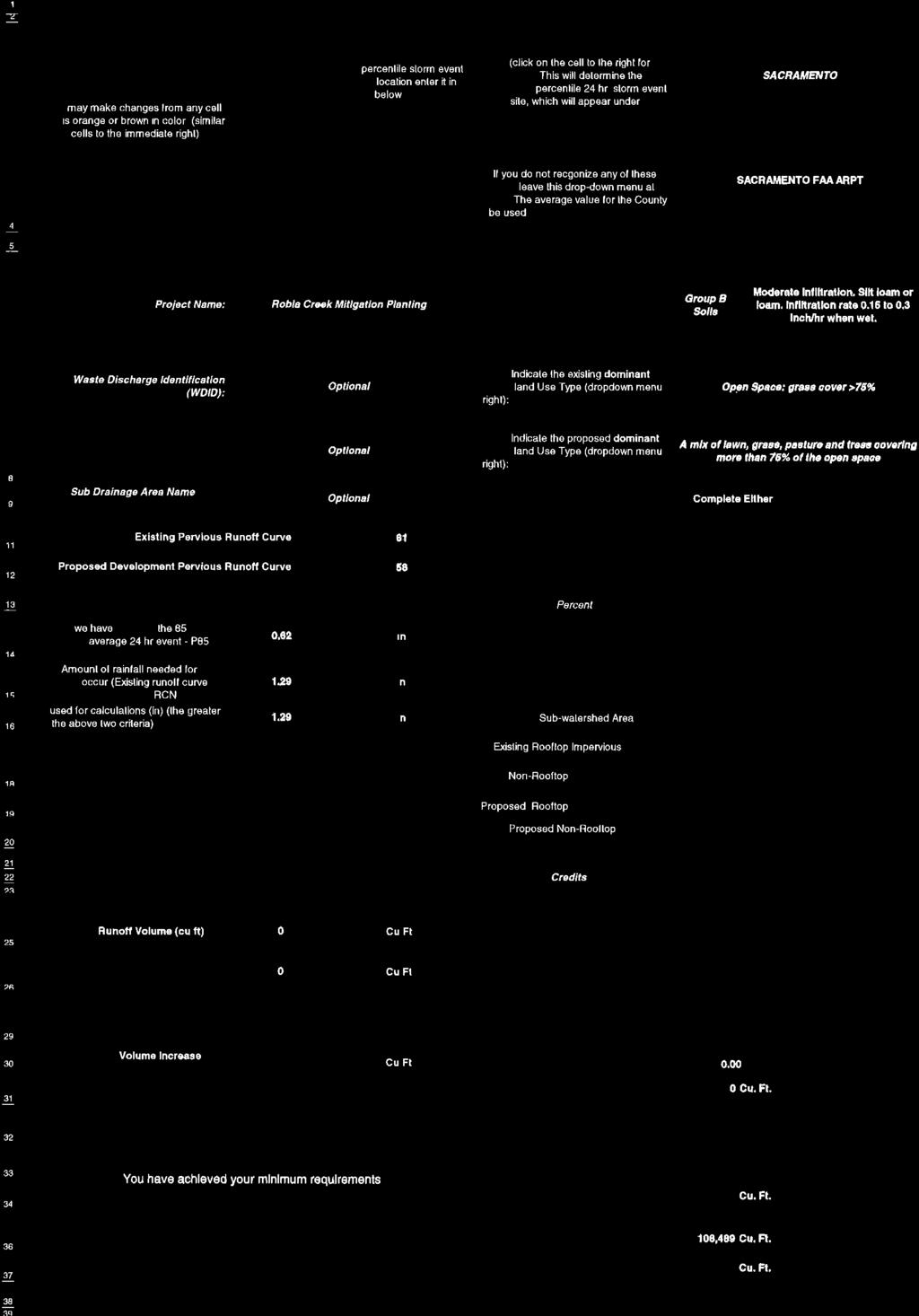
79
80 A B C D E F G Version 8/17/2011 Risk Determination Worksheet Step 1 Step 2 Step 3 Determine Sediment Risk via one of the options listed: 1. GIS Map Method - EPA Rainfall Erosivity Calculator & GIS map 2. Individual Method - EPA Rainfall Erosivity Calculator & Individual Data Determine Receiving Water Risk via one of the options listed: 1. GIS map of Sediment Sensitive Watersheds provided 2. Site Specific Analysis (support documentation required) Determine Combined Risk Level
81 1 2 Sediment Risk Factor Worksheet A) R Factor A B C Entry 3 4 Analyses of data indicated that when factors other than rainfall are held constant, soil loss is directly proportional to a rainfall factor composed of total storm kinetic energy (E) times the maximum 30-min intensity (I30) (Wischmeier and Smith, 1958). The numerical value of R is the average annual sum of EI30 for storm events during a rainfall record of at least 22 years. "Isoerodent" maps were developed based on R values calculated for more than 1000 locations in the Western U.S. Refer to the link below to determine the R factor for the project site. 5 R Factor Value B) K Factor (weighted average, by area, for all site soils) The soil-erodibility factor K represents: (1) susceptibility of soil or surface material to erosion, (2) transportability of the sediment, and (3) the amount and rate of runoff given a particular rainfall input, as measured under a standard condition. Fine-textured soils that are high in clay have low K values (about 0.05 to 0.15) because the particles are resistant to detachment. Coarse-textured soils, such as sandy soils, also have low K values (about 0.05 to 0.2) because of high infiltration resulting in low runoff even though these particles are easily detached. Medium-textured soils, such as a silt loam, have moderate K values (about 0.25 to 0.45) because they are moderately susceptible to particle detachment and they produce runoff at moderate rates. Soils having a high silt content are especially susceptible to erosion and have high K values, which can exceed 0.45 and can be as large as Silt-size particles are easily detached and tend to crust, producing high rates and large volumes of runoff. Use Site-specific data must be submitted. Site-specific K factor guidance 9 K Factor Value C) LS Factor (weighted average, by area, for all slopes) The effect of topography on erosion is accounted for by the LS factor, which combines the effects of a hillslopelength factor, L, and a hillslope-gradient factor, S. Generally speaking, as hillslope length and/or hillslope gradient increase, soil loss increases. As hillslope length increases, total soil loss and soil loss per unit area increase due to the progressive accumulation of runoff in the downslope direction. As the hillslope gradient increases, the velocity and erosivity of runoff increases. Use the LS table located in separate tab of this spreadsheet to determine LS factors. Estimate the weighted LS for the site prior to construction. 12 LS Table LS Factor Value Watershed Erosion Estimate (=RxKxLS) in tons/acre Site Sediment Risk Factor Low Sediment Risk: < 15 tons/acre Medium Sediment Risk: >=15 and <75 tons/acre High Sediment Risk: >= 75 tons/acre 6.02 Low 0.43
82 Receiving Water (RW) Risk Factor Worksheet Entry Score A. Watershed Characteristics yes/no A.1. Does the disturbed area discharge (either directly or indirectly) to a 303(d)-listed waterbody impaired by sediment (For help with impaired waterbodies please visit the link below) or has a USEPA approved TMDL implementation plan for sediment?: OR A.2. Does the disturbed area discharge to a waterbody with designated beneficial uses of SPAWN & COLD & MIGRATORY? (For help please review the appropriate Regional Board Basin Plan) Region 1 Basin Plan Region 2 Basin Plan Region 3 Basin Plan Region 4 Basin Plan Region 5 Basin Plan Region 6 Basin Plan Region 7 Basin Plan Region 8 Basin Plan Region 9 Basin Plan No Low
83 Combined Risk Level Matrix Receiving Water Risk Low Level 1 Sediment Risk Low Medium High Level 2 High Level 2 Level 3 Project Sediment Risk: Low 1 Project RW Risk: Low 1 Project Combined Risk: Level 1
84
85 Average W atershed Slope (% ) Sheet Flow Length (ft) < LS Factors for Construction Sites. Table from Renard et. al., 1997.
86


87 THIS SHEET FOR SWPPP ONLY