Energy Production Systems Engineering
|
|
|
- Georgia Gallagher
- 5 years ago
- Views:
Transcription


1 Welcome to Energy Production Systems Engineering USF Polytechnic Engineering Session 10: Environmental Controls Spring 2012
2 Plant Environmental Control Systems
3 Power plant Environmental Controls All emissions water, air, solid waste This presentation on atmospheric emission control Particulate Emission Control Nitrogen Oxides Emission Control Sulfur Dioxide Emission Control Combination NOX SO2 removal Hazardous Air Pollutant control Continuous Emissions Monitoring 3
4 Particulate Emission Control Bottom ash bottom of boiler Economizer ash removed after economizer smaller Fly Ash removed at electrostatic precipitator or fabric filter 4
5 Electrostatic Precipitator TR set HV DC between HV electrode and grounded plate Particles collect on plates rappers mechanically vibrate plate and remove particles Precipitator cross section large to reduce velocity Increases treatment time. TR set 25kV to 125kV Rapping Systems hammers, vibrators, dropped weights 5
6 Resistivity = measure of how easily the ask acquires electric charge Varies with Moisture, SO3, chemical composition, temperature. For low sulfur coal, add SO3 to reduce resistivity. Weighted wire or pipes as electrodes 6
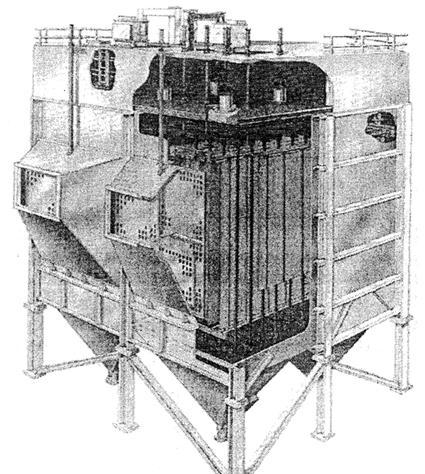
7 Typical Precipitator 7
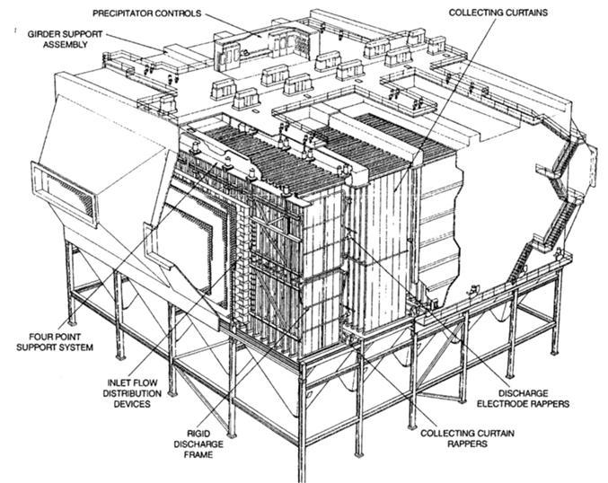
8 8
9 Fabric Filters Filter media sewn into cylindrical tubes (bags) Reverse gas fabric filter or pulse jet cleaning type. 9
10 Reverse Gas Fabric Filter Operating Cycle 10
11 Cleaning Cycle 11
12 Pulse Jet Fabric Filter Tolerates higher velocity Cleaned more thoroughly Smaller footprint for same air flow 12
13 Pulse Jet Fabric Filter Filtering 13
14 Online Cleaning Cycle 14
15 Offline Cleaning Cycle 15
16 Isolated for Maintenance 16
17 Pulse Jet Fabric Filter Filtering 17
18 Alternate Particulate Control Technologies Cyclone Collectors Uses centrifugal force to separate fly ash Wet Venturi Scrubber Use liquid to capture fly ash. Flue gas velocity accelerates in venturi where water droplets are used to collect ash. 18
19 Cyclone Separator 19
20 Nitrogen Oxides Emissions Control 90% NO, 10% NO2 Nitrogen in air (thermal NOx) 25% Nitrogen in fuel (fuel NOx) 75% Low temperature (thermal NOx formation) Control Fuel / Air ratio (fuel NOx formation) Combustion control and/or post combustion control 20
21 Combustion Control Reduce temperature Reduce Oxygen concentration Reduce reaction time in Oxygen rich, high temp condition Low NOx burners 2 separate registers 2 air paths 21

22 Internal Fuel Staged Low NOx Burner 22

23 Low NOx burner A High Temperature fuel rich zone B Production of reducing species zone C NOx decomposition zone D Char oxidizing zone 23
24 Corner Fired System LNCFS Low NOx Concentric Firing System (retrofits) PM pollution minimum system (new) LNCFS auxiliary air directed at 25O of air/coal stream thereby reducing air in fuel stream OFA overfired air provides vertical air staging over furnace height. PM splits fuel and air stream into two, one fuel rich, one fuel lean. 24
25 LNCFS (Auxiliary air) 25
26 CT NOx control Reduction of flame temperature using Steam Water N2 Premixing of fuel/air upstream of combustion zone 26
27 Post combustion Control Selective Catalytic Reduction Systems (SCR) Ammonia and NO react in presence of catalyst to form N2 and H2O 27
28 Desired SCR Reactions (exothermic) as Ammonia and NOX flow over catalyst 4NO + 4NH 3 + O 2 (catalyst) 4N 2 + 6H 2 O + heat 2NO 2 + 4NH 3 + O 2 (catalyst) 3N 2 + 6H 2 O + heat 28
29 Undesirable SCR Reactions (exothermic) as Ammonia and NOX flow over catalyst 2SO 2 + O 2 2SO 3 (SO 2 oxidation) 2NH 3 + SO 3 + H 2 O NH 4 HSO 4 (ammonium bisulfate formation) 2NH 3 + 2SO 3 + H 2 O + 0.5O 2 2NH 4 HSO 4 (ammonium sulfate formation) 29
30 SO2 oxidation increased above 700 o F, so SCR temps typically held 650 o F to 700 o F No less than 570 o F to minimize formation of ammonia salts For non sulfur fuel, max temp 780 o F (vanadium/titanium catalyst) Ammonium sulfate and bisulfate are salts and can deposit on surfaces downstream. Ammonia slip may effect reuse of fly ash collected. Anhydrous ammonia 100% NH 3 Aqueous 25% NH 3, 75% H 2 O 30
31 SCR Arrangement High Dust Catalyst located at the outlet of the economizer and upstream of the air heater Low Dust Catalyst located at the outlet of the hot side ESP and upstream of the air heater Tail End Catalyst located at the outlet of particulate removal and FGD system and upstream of stack. 31
32 High Dust SCR Arrangement 32
33 Low Dust SCR Arrangement 33
34 Tail End SCR Arrangement 34
35 Catalyst poisoned by alkali metals such as: Arsenic Lead Beryllium Manganese Cadmium Mercury Calcium Nickel Chromium Thorium Copper Uranium 35
36 Post combustion Control Selective Non Catalytic Reduction System (SNCR) Depend on temperature, gas mixing and reaction time rather than catalyst. Use ammonia or urea as reagents. Injection Temperature = 1500 o F to 2200 o F 36
37 Desired NSCR Reactions (exothermic) as reagent and NOX flow over catalyst 4NO + 4NH 3 + O 2 -> 4N 2 + 6H 2 O + heat (ammonia) 4NO + 2(CO(NH 2 ) 2 + O 2 -> 4N 2 + 2CO 2 + 4H heat (urea) Note only remove NO not NO2 (does cover about 95% of NOx) 37
38 Undesirable NSCR Reactions (exothermic) as reagent and NOX flow over catalyst Same as SCR plus: 4NH 3 + 5O 2 -> 4NO + 6H 2 O (ammonia oxidation to NO) 4NH 3 + 3O 2 -> 2N 2 + 6H 2 O (ammonia thermal decomposition) 2NH 3 + 2O 2 -> N 2 O + 3H 2 O (nitrous oxide emission 38
39 Sulfur Dioxide Emission Control Dry Furnace Sorbent Injections (FSI) Limestone forms Calcium oxide (CaO) (calcination) and reacts with SO 2 and Oxygen to form calcium sulfate CaSO 4 (Sulfation) Following are equations of reaction depending on if Limestone, dolomite, lime, or hydrated lime are reagents 39
40 Desulfurization 40
41 41
42 Post combustion Wet scrubbing 1.Forced Oxidized Wet Limestone 2.Magnesium Enhanced Wet Lime 3.Seawater 4.Ammonium Sulfate 42
43 Wet FGD Systems Comparison of Attributes 43
44 Forced Oxidized Wet Limestone Ball Mill crush limestone and mix with water. Slurry pumped into absorber tower where slurry mixes with gas. Forced Oxidation compressors inject air into reaction tank to convert calcium sulfite (CaSO 3 ) into gypsum (CaSO 4 *2H 2 O) Mist eliminators remove slurry droplets from gas on exit of tower 44
45 Wet limestone FGD system 45
46 Flow diagram for wet limestone grinding system 46

47 Absorber cutaway view 47

48 Counter flow mist eliminator 48
49 Magnesium enhanced process Higher removal efficiency Absorber tower height less Pumping head lower Required Lime to Gas ratio less 49
50 Seawater and Ammonia are emerging technology Seawater injection into absorber tower to scrub SO2 50
51 Seawater scrubber PFD 51
52 Ammonia scrubbing Very high efficiency Resalable ammonium sulfate fertilizer byproduct 52
53 Ammonium sulfate PFD 53
54 Semidry Scrubbing Ca(OH) 2 contacts gas as slurry and dried before exit. Benefits: Lower energy usage & water consumption FGD byproducts dry Reduced slurry requirements Less complex system Disadvantage Greater reagent quantities needed and more solids produced 54
55 Continuous Emission Monitoring System (CEMS) In situ systems monitor the flue gas at the conditions present in the stack at the monitoring location Extractive systems draw gas sample to remote location. Absorption Spectroscopy scattering of light Opacity Monitoring visible light Gas Monitoring IR Analysis Luminescence Spectroscopy light emission of molecules when excited Electro-analytical chemical reactions 55
56 End of Environmental Control System
57 Energy Production Systems Engineering USF Polytechnic Engineering End of Session 10: Environmental Controls Spring 2012