Vapor-Intrusion Management Plan Lockheed Martin Middle River Complex 2323 Eastern Boulevard Middle River, Maryland
|
|
|
- Arleen Lane
- 5 years ago
- Views:
Transcription
1 Vapor-Intrusion Management Plan Lockheed Martin Middle River Complex 2323 Eastern Boulevard Middle River, Maryland Prepared for: Lockheed Martin Corporation Prepared by: Tetra Tech, Inc. December 8, 2010 Michael Martin, P.G. Regional Manager Eric M. Samuels Project Manager 7708 TETRA TECH LOCKHEED MARTIN, MIDDLE RIVER COMPLEX VAPOR-INTRUSION MANAGEMENT PLAN
2 TABLE OF CONTENTS Section Page ACRONYMS... iii 1 INTRODUCTION PROGRAM MANAGEMENT SITE VI MANAGER RECORDS SITE WALKS AND THE BASELINE BUILDING AUDIT WRITTEN POLICY, PLANS, AND PROTOCOLS Source Management Protocols Maintenance and Housekeeping Plans COMMUNICATIONS PROGRAM Notification of Remodeling and Renovation Notification of Short-Term Activities Affecting IAQ Feedback TECHNICAL MANAGEMENT BACKGROUND DEVELOPMENT OF VI AND IAQ ACTION LEVELS Attenuation-Factor Calculations Sub-Slab Vapor Action-Level Calculations Application of Action Levels SSD SYSTEM SHUTDOWN MANAGEMENT OF POTENTIAL VAPOR-INTRUSION RISKS MANAGEMENT OF POTENTIAL ACUTE RISKS MANAGEMENT OF POTENTIAL CHRONIC RISKS EXIT STRATEGY COMMUNICATION OF POTENTIAL RISK REFERENCES TETRA TECH LOCKHEED MARTIN, MIDDLE RIVER COMPLEX VAPOR-INTRUSION MANAGEMENT PLAN PAGE i
3 TABLE OF CONTENTS (continued) APPENDICES APPENDIX A SUPPORTING PLOTS FOR ATTENUATION-FACTOR CALCULATIONS LIST OF FIGURES Page Figure 3-1 Action-Level-Calculation Flow Chart LIST OF TABLES Page Table 3-1 Indoor Worker Risk-Based Screening Levels for Ambient Air Table 3-2 Indoor Air Screening Levels for MRC Table 3-3 Summary of Attenuation Factors Based on Co-located Sampling Rounds 1-3 (Pre-SSD) Table 3-4 Summary of Action Levels Table 3-5 Action Level Decision Matrix Table 4-1 Action Levels for Acute Exposure TETRA TECH LOCKHEED MARTIN, MIDDLE RIVER COMPLEX VAPOR-INTRUSION MANAGEMENT PLAN PAGE ii
4 ACRONYMS µg/m 3 AF atm-m 3 /mol ca DTSC ESH FID HQ HVAC IAQ Lockheed Martin MDE MRC MSDS nc OSHA PCE PID ppm SSD STEL SV TCE TWA USEPA VI VOC micrograms per cubic meter attenuation factor atmospheres per cubic meter/mole carcinogenic California Department of Toxic Substances Control environment, safety, and health flame-ionization detectors hazard quotient heating, ventilation, and air conditioning indoor air quality Lockheed Martin Corporation Maryland Department of the Environment Middle River Complex material safety data sheet non-carcinogenic Occupational Safety and Health Administration tetrachloroethene photoionization detector parts per million sub-slab depressurization short-term exposure limit sub-slab vapor trichloroethene time-weighted average United States Environmental Protection Agency vapor intrusion volatile organic compound 7708 TETRA TECH LOCKHEED MARTIN, MIDDLE RIVER COMPLEX VAPOR-INTRUSION MANAGEMENT PLAN PAGE iii
5 Section 1 Introduction Vapor intrusion (VI) is the migration of volatile chemicals from the subsurface into the indoor air of buildings above the location of chemical contamination. This document was developed as a resource for personnel at the Lockheed Martin Middle River Complex (MRC) who that need to manage known VI pathways and/or investigate as yet unknown potential VI pathways at the site that may adversely affect facility indoor air quality (IAQ). This document provides a general framework for addressing VI from a program management, technical management, and risk management perspective. VI should be evaluated as a potential human exposure pathway whenever volatile chemicals are present in soil, soil gas, or groundwater underlying existing structures or has the potential to underlie future buildings. The physical properties of volatile chemicals can result in their migration through unsaturated soil into the indoor air of buildings near zones of subsurface contamination. The United States Environmental Protection Agency (USEPA) defines a chemical as volatile if its Henry s Law constant is atmospheres per cubic meter/mole (atm-m 3 /mol) or greater (USEPA, 2002). (Henry s Law constants are calculated to characterize the equilibrium distribution of concentrations of volatile, soluble chemicals between gas and liquid; i.e., the solubility of a gas in a liquid at a particular temperature is proportional to the pressure of that gas above the liquid.) Volatile organic compounds (VOCs) including such common chemicals as petroleum hydrocarbons (e.g., benzene) and chlorinated solvents (e.g., trichloroethylene [TCE]) are the class of chemicals of greatest interest for this pathway. The USEPA has identified more than 100 chemicals with sufficient volatility and toxicity to pose a theoretical VI hazard (USEPA, 2002). These chemicals should thus be included in any VI investigation or program if they are known to have been used or released at a site, or it might reasonably be assumed that they may have been used or released at a site. Typically, the potential for VI is evaluated during a site investigation TETRA TECH LOCKHEED MARTIN, MIDDLE RIVER COMPLEX VAPOR-INTRUSION MANAGEMENT PLAN PAGE 1-1
6 The site-specific VI risk assessment for the MRC indicates the possible presence of regulatorily unacceptable risks associated with VI; appropriate response actions were implemented to mitigate these risks. Reasonable alternatives are considered when selecting response actions, including passive or active ventilation systems, floor sealants, or other mitigation measures. The potential for VI in future structures should be addressed during design, and any necessary measures to reduce VI included in the design as well as in subsequent construction costs. A typical approach for assessing potential risks posed by the VI pathway, as well as mitigation and remediation options, is summarized below: Evaluate whether exposure to the vapors poses an acute (immediate) risk to building occupants: This can include both acute health risks and the risk of explosion. For acute risks, field instruments will be used and comparisons made to Occupational Safety and Health Administration (OSHA) short-term and ceiling exposure levels (see Section 4.1). If acute risks from VI are identified, the affected area may need to be evacuated until the risks are mitigated. If no acute risks are identified, a screening level VI evaluation may be conducted. Conduct a screening level assessment of site contaminants: This evaluation typically involves comparing site soil gas or groundwater data to conservative risk based screening values. If site concentrations are below the screening levels, a low potential for VI risk exists. If contaminant concentrations in affected media exceed risk based screening values, then a site-specific VI model may be evaluated. Conduct a site-specific VI pathway evaluation: Site-specific data are collected that may include sub-slab soil gas and/or indoor air samples. Multiple lines of evidence may be used to evaluate the magnitude and extent of VI. Depending on the results of the investigation and comparison to site-specific action levels, no further action might be deemed necessary, or perhaps mitigation may be warranted. Evaluate mitigation/remediation options, if necessary: Mitigation involves techniques that prevent (or minimize) subsurface vapors from entering a building s indoor air from subsurface contamination. Common mitigation measures include installation of a passive venting system, sub-slab depressurization or pressurization devices, sealing cracks, sumps, and other potential preferential pathways, and installing vapor proof membranes. At active facilities, land (or building) 7708 TETRA TECH LOCKHEED MARTIN, MIDDLE RIVER COMPLEX VAPOR-INTRUSION MANAGEMENT PLAN PAGE 1-2
7 use-controls may also be an option to control exposure. Remediation treats and removes chemicals from contaminated subsurface media, such as soil and groundwater. Common remediation options include soil removal, soil gas extraction, and groundwater treatment. Mitigation and remediation may be performed concurrently or individually, depending on site needs TETRA TECH LOCKHEED MARTIN, MIDDLE RIVER COMPLEX VAPOR-INTRUSION MANAGEMENT PLAN PAGE 1-3
8 Section 2 Program Management As part of VI management at the Middle River Complex, Tetra Tech developed VI-specific action levels and policies/protocols. Similar policies/protocols may already be in effect at the MRC that can be modified or adapted to meet VI management needs. These steps can then be integrated into the facility-level operations program and policies. 2.1 SITE VI MANAGER An on-site person will be assigned as the VI manager at the MRC and provided with sufficient authority to implement the comprehensive VI management plan. Appropriate training and other steps will ensure that the VI manager is familiar with the principles of VI, IAQ, and the elements of the VI management plan. The VI manager will be responsible for the following: ensuring that building drawings and records are up to date training staff, as necessary coordinating monthly building walk-through with tenants reviewing with tenants, before work begins, any maintenance and housekeeping plans for their potential VI effects reviewing contracts and negotiations with contractors for anything that might increase potential VI, such as drilling through the slab, ventilation changes, and running of conduit from basement locations communicating with tenants/occupants about building activities and occupant/tenant responsibilities in managing VI Key Lockheed Martin personnel, as well as tenant staff, should be identified and assigned clearly defined VI responsibilities. We recommend that each tenant identify their own VI manager(s) so the site VI manager will have specific individuals within the tenant organization to coordinate and communicate. All personnel associated with VI management should understand the fundamentals of both VI and indoor air quality, and be trained as necessary to incorporate 7708 TETRA TECH LOCKHEED MARTIN, MIDDLE RIVER COMPLEX VAPOR-INTRUSION MANAGEMENT PLAN PAGE 2-1
9 management thereof as part of their daily responsibilities. Key Lockheed Martin and tenant personnel who may assist with VI management may include the following parties: building managers building engineers environmental, health, and safety personnel heating, ventilation, and air conditioning (HVAC) personnel building maintenance personnel All contractors working on-site will have their proposed work evaluated by VI management personnel at least one month in advance to assess how their proposed tasks might affect potential VI. 2.2 RECORDS An organized system should be developed to collect and maintain the following building records: as built blueprints, including modifications to reflect current conditions up-to-date drawings of all tenants build outs and interior renovations records of major changes in space use not reflected in original design drawings of pressure relationships (i.e. pressurized versus non-pressurized areas) operating and maintenance plans and schedules inventory of any products or materials that are a potential source of VOCs Documents that may be useful in organizing these records include: construction documents commissioning reports operating manuals HVAC maintenance records remodeling and renovation records records of equipment modifications/replacements 7708 TETRA TECH LOCKHEED MARTIN, MIDDLE RIVER COMPLEX VAPOR-INTRUSION MANAGEMENT PLAN PAGE 2-2
10 2.3 SITE WALKS AND THE BASELINE BUILDING AUDIT As part of VI management, baseline building conditions will be documented, and these records will be updated periodically. A whole-building walk through will be conducted by the site VI manager and tenant representatives to record the status of existing, as well as potential, conduits for sub-slab vapor. Simple measurements of pressure relationships and airflow patterns may help identify locations that may be more susceptible to VI. These measurements will be recorded and kept as a baseline for future comparison. If appropriate, areas where more detailed information may be needed to complete the basic profile can be identified and placed in the baseline audit at a later date. The basic conditions of the building exterior, its mechanical systems, the HVAC design, and occupied spaces will be documented. Potential problems identified in the baseline audit that might facilitate VI should be rectified as soon as possible (see Section 3). The site VI manager will ask Lockheed Martin to issue appropriate work orders so that the problems can be corrected. Managers should plan and budget for the remediation of major problems requiring significant expenditure. Site walks and audits will be repeated monthly and the results recorded. Any changes in the facility that may affect VI, such as uncovering an area of flooring with cracks or holes, will be documented and reported to the designated site VI manager within 24 hours of discovery. 2.4 WRITTEN POLICY, PLANS, AND PROTOCOLS Written policies, plans, and protocols are important because they are conducive to minimizing VI and establishing and maintaining good IAQ. Policies can be used to train and guide building personnel as well as guide housekeeping, maintenance, and construction or remodeling activities Source Management Protocols For locations where a source or potential source of VI has been identified, specific written protocols will be established to manage those sources and prevent the creation of possible conduits from the subsurface that might increase potential exposures to sub-slab contaminants through VI. Current known source locations include beneath the Building A Plating Shop and beneath the southern part of the Building C Basement. These protocols are in addition to the ongoing operation and maintenance programs for the sub-slab depressurization (SSD) systems operating at these locations TETRA TECH LOCKHEED MARTIN, MIDDLE RIVER COMPLEX VAPOR-INTRUSION MANAGEMENT PLAN PAGE 2-3
11 Protocols that may be implemented include: protocols to provide adequate exhaust ventilation, either localized (e.g. fans and/or venting) or centralized, at all areas with identified or potential sources of VI emissions, to reduce potential airborne concentrations of VI contaminants protocols to move personnel away from known source areas or suspected source areas if localized exhaust or additional ventilation cannot be provided to reduce airborne concentrations of VI contaminants below action levels protocols to provide for circulation of adequate outside air during winter months when doors and windows are closed protocols to review all proposed operations to be performed by tenants and contractors near known or suspected source areas by the site VI manager protocols to prevent work from being performed in locations with known or suspected VI without authorization by the VI manager protocols to ensure that all necessary steps will be taken to prevent breaching of the slab in areas of known or suspected sub-slab sources of contaminants protocols to collect IAQ and sub-slab vapor data semi-annually protocols to communicate VI information to tenants, contractors, and other site personnel These protocols can be included as appendices to this document Maintenance and Housekeeping Plans Written maintenance and housekeeping plans will be reviewed to ensure that they include practices to maintain good IAQ and minimize potential VI. Examples of housekeeping protocols include such tasks as prompt clean up of spills and trash, and keeping the areas around mitigation equipment unobstructed and clean. Material safety data sheets (MSDS) for all chemicals used in housekeeping will be reviewed to ensure that they do not contain any of the target compounds associated with VI. The presence of these compounds in the work environment might affect the results of routine sub-slab vapor and indoor air sampling. Examples of maintenance protocols may include such tasks as scheduled maintenance/evaluation of HVAC functions (including equipment, fans, and filters), prompt repair of faulty equipment, and steps to prevent compromising the function of SSD systems TETRA TECH LOCKHEED MARTIN, MIDDLE RIVER COMPLEX VAPOR-INTRUSION MANAGEMENT PLAN PAGE 2-4
12 2.5 COMMUNICATIONS PROGRAM A communications program will be developed or the current communications program modified to address VI. Specifically, a VI communication program for the MRC site will: clarify the responsibilities of facility managers, staff, tenants, and contractors in maintaining a safe and comfortable indoor environment respond effectively to potential VI issues and prevent situations that may result in mistrust and misunderstandings prevent disruptive and costly remedies by reacting before problems arise help occupants improve their work environment through positive contributions To identify critical areas of responsibility and communication, an understanding of site-specific general responsibilities and communication needs will be developed. Personnel will be provided with information about what they can do to minimize known or potential VI Notification of Remodeling and Renovation As part of the lease agreement, the tenant must notify the site VI manager and Lockheed Martin of any proposed remodeling or renovation in the building at least two weeks before the work begins. Likewise, Lockheed Martin will notify the tenant contact of any major renovation, remodeling, or maintenance that will be performed on site. In each case, the notification should be submitted in writing. It must include the proposed work plan and associated mitigation measures that will be undertaken to minimize potential VI and maintain good IAQ during construction Notification of Short-Term Activities Affecting IAQ Notification procedures will be developed for any activities that could affect VI. Examples of short-term activities include interruption of electrical service that shuts down SSD systems, disruption of HVAC operations that might reduce positive pressures (thereby increasing the potential for VI), and drilling through the slab to install electrical conduit or ventilation ductwork. Tenants and occupants will also be notified about the measures that will be taken during these activities to minimize VI and maintain IAQ TETRA TECH LOCKHEED MARTIN, MIDDLE RIVER COMPLEX VAPOR-INTRUSION MANAGEMENT PLAN PAGE 2-5
13 2.5.3 Feedback To coordinate and cooperate with tenant operations, tenants will receive advance notice of any VI activities that may occur on-site. These include on-site sampling of environmental media, or the assessment, installation, or expansion of the existing VI-mitigation systems. This advance notice will allow the tenant to shift on-site processes to other locations, to minimize disruption of overall site operations and production. A procedure to keep the tenant informed of work associated with VI-related activities will be developed. It should describe the activity and the area in which it will be performed. Contact persons and their telephone numbers, as well as the names and phone numbers of individuals to call for more detailed information, will be provided. Progress and the expected length of any on-site work should be identified and included in the notification TETRA TECH LOCKHEED MARTIN, MIDDLE RIVER COMPLEX VAPOR-INTRUSION MANAGEMENT PLAN PAGE 2-6
14 Section 3 Technical Management 3.1 BACKGROUND This section of the VI management plan addresses the development and application of sitespecific risk based action levels that will be used to assess the potential for VI at the MRC, as well as to evaluate when mitigation may be needed or discontinued. These action levels will guide: whether additional IAQ and SV monitoring are indicated whether mitigation is required emergency response USEPA and Maryland Department of the Environment (MDE) accept that chemical concentrations above a screening/action level do not automatically designate a site as dirty or necessarily trigger a response action; however, exceeding a screening/action level suggests that further evaluation of the potential risks posed by site contaminants is appropriate. As such, the action levels to be discussed represent values that will be used to make management decisions regarding the need for additional actions to address potential VI concerns. 3.2 DEVELOPMENT OF VI AND IAQ ACTION LEVELS The default screening levels for industrial air set forth in EPA s Regional Screening Levels for Chemical Contaminants at Superfund Sites (USEPA, 2009) are currently used to evaluate chemical contaminants in indoor air at the MRC, except for TCE. A summary of the EPA default screening levels for the VI contaminants of concern at the MRC is presented in Table 3-1. The lowest carcinogenic (ca) or noncarcinogenic (nc) screening level is used to screen the contaminants identified in sub-slab vapor in the semi-annual sub-slab vapor and indoor air sampling event. Although EPA screening levels are defined for a carcinogenic-risk of (one 7708 TETRA TECH LOCKHEED MARTIN, MIDDLE RIVER COMPLEX VAPOR-INTRUSION MANAGEMENT PLAN PAGE 3-1
15 in 1,000,000), carcinogenic risk is evaluated at the risk level at this site in accordance with MDE requirements. For TCE, MDE has specified a screening level of 25 µg/m 3, at a risk level of (MDE, 2009). A summary of the indoor air screening levels used at this site is presented in Table 3-2. In the past, these default screening values were used to evaluate historical data collected as part of ongoing investigations at Block I. Sub-slab vapor sampling results were compared to sub-slab vapor screening values, which were derived in accordance with methods discussed in Appendix D of USEPA, SV screening values were calculated by dividing the default indoor air screening levels (Table 3-2) by a conservative attenuation factor (AF) of 0.1, obtained from USEPA, An AF represents the factor by which subsurface-vapor concentrations migrating into indoor air spaces are reduced due to diffusive, advective, and/or other attenuating mechanisms. Exceedance of a screening level indicates a potential risk from VI and that further evaluation is needed. Sub-slab vapor screening values may not reflect actual site conditions because they are based on a default attenuation factor. Site-specific attenuation factors may be higher or lower, which in turn may overestimate or underestimate potential risks. To address this uncertainty and provide the site VI manager with a tool to address potential VI before it reaches levels of potentially regulatorily unacceptable risk, new site-specific action levels for the MRC were developed. These new action levels incorporate site-specific factors that the existing screening levels lacked. They reflect site conditions at the MRC, since they are based on co-located sub-slab vapor and IAQ sampling data. Where these data are adequate, the new action levels incorporate attenuation factors derived from the co-located data. These site-specific attenuation factors reflect both the characteristics of the chemicals that affect potential VI (i.e., vapor pressure, molecular weight, Henry s Law constant, etc.), as well as the particular building characteristics, such as slab thickness, porosity, ventilation, etc. To calculate the new site-specific action levels for the MRC, EPA and MDE screening values were used in conjunction with chemical- and site-specific attenuation factors. Note that the new action levels are specific to the MRC, and may not be applicable at other locations due to differences in geology, hydrogeology, building characteristics, etc TETRA TECH LOCKHEED MARTIN, MIDDLE RIVER COMPLEX VAPOR-INTRUSION MANAGEMENT PLAN PAGE 3-2
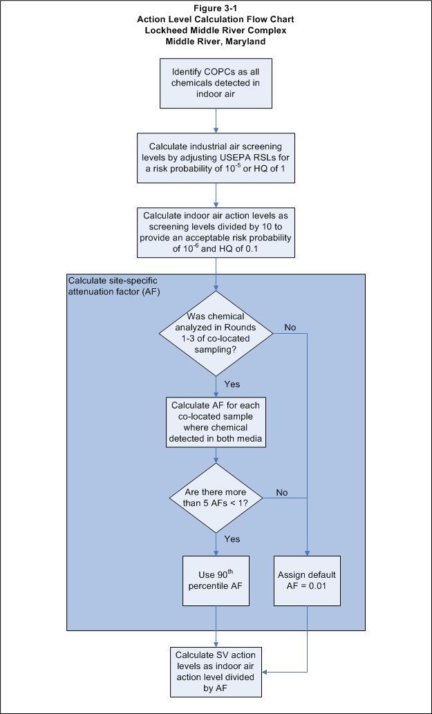
16 3.2.1 Attenuation Factor Calculations To calculate site-specific action levels for sub-slab vapor and indoor air at the MRC, site-specific attenuation factors (AFs) were calculated (where possible). AFs were calculated using chemical concentrations measured in co-located sub-slab vapor and indoor air samples from the first three rounds of sampling at the MRC. This sample set represents conditions at the MRC before activation of the SSD systems. Since the action levels will ultimately be used to determine whether to shut down the SSD system (and then whether it needs to be reactivated), AFs should represent the site without the influence of a mitigation system. AFs are valid only when migration from SV to indoor air is occurring. An SSD system is designed to minimize this migration. AFs were calculated by dividing the measured indoor air concentration by the sub-slab vapor concentration for each co-located sample in sampling rounds 1 3. The data sets for all buildings were combined to provide as large a data set as possible to determine site-specific AFs. Table 3-1 presents a summary of the AFs for each chemical. Figure 3-1 includes a flow chart illustrating AF calculation. The data set from sampling rounds 1 3 was evaluated for possible background effects that might bias the attenuation factors. Indoor air concentrations versus sub-slab vapor concentrations were plotted along with average background concentrations for each chemical. These are shown in Appendix A. For some chemicals, the influence of background concentrations is significant; these are noted in Table 3-3. Also noted in this table is the number of samples where the AF was greater than 1, which indicates a background source of that chemical. When an AF is greater than 1, the indoor air concentration is greater than the sub-slab vapor concentration. This indicates the presence of some other contributor to the indoor air concentration (e.g., ambient levels in outdoor air or an indoor source of the chemical). Co-located samples with AFs greater than 1 were excluded from the calculations because these samples do not accurately represent vapor intrusion from sub-slab to indoor air. No further adjustments were made to the AFs due to the influence of background concentrations. Data from sampling rounds 6 8 were evaluated for inclusion in the AF calculations, because data from sampling rounds 1 3 were limited. During rounds 6 8, co-located samples were taken 7708 TETRA TECH LOCKHEED MARTIN, MIDDLE RIVER COMPLEX VAPOR-INTRUSION MANAGEMENT PLAN PAGE 3-3
17 while the SSD system was operational. Although rounds 6 8 had considerably more data, concentrations in the sub-slab vapor were generally several orders of magnitude lower than those observed in sampling rounds 1 3 because the SSD system was operating. The indoor air concentrations measured in rounds 6 8, however, were generally one to two orders of magnitude lower than those measured in rounds 1 3. This resulted in higher AFs (greater than 0.1) for most chemicals. These AFs are not considered representative of vapor intrusion from sub-slab vapor to indoor air, since operation of the SSD system may be influencing the measured concentrations; therefore, data from rounds 6 8 were not used in the site-specific AF calculations. Results from sampling rounds 1 3 data (Table 3-3) provided sufficient data (i.e., a minimum of five AFs less than 1) to calculate site-specific AFs for only four chemicals: cis-1,2-dichloroethene, tetrachloroethene (PCE), TCE, and toluene. Five AFs less than 1 was considered a reasonable minimum number to perform statistical calculations, as fewer AFs would likely result in no differences between the percentiles of the calculated AFs for each chemical. Cumulative distribution functions of the AFs for these chemicals are provided in Appendix A. The 90 th percentile AF was selected to calculate the site-specific SV action levels for this site. For the remaining chemicals, the absence of adequate co-located data (non-detected, blank contaminated, estimated below detection-limits) or other uncertainties and/or lack of quantification in the data set prevented calculation of a site-specific AF. A default AF of 0.01 was assigned to these chemicals. This is a conservative assumption, as an AF of 0.01 is the maximum AF recommended by California Department of Toxic Substances Control (DTSC) (2005) (representing sub-slab to basement vapor intrusion for residential buildings). An AF of 0.01 is also a factor of two greater than the median AF of for sub-slab vapor to indoor air in EPA s Vapor Intrusion Database (2008). A range of site-specific AFs (based on comparisons of SV and IAQ contaminant concentrations) was calculated for each contaminant for which sufficient data above method-detection limits were available for both SV and IAQ measurements. The resulting variability in AFs is understandable, given that the samples were collected in several large adjoining buildings with different foundation types, potential pathways for VI, ventilation dynamics, and building sizes, allowing for variation in vapor migration and dispersion within the buildings. Therefore, 7708 TETRA TECH LOCKHEED MARTIN, MIDDLE RIVER COMPLEX VAPOR-INTRUSION MANAGEMENT PLAN PAGE 3-4
18 uncertainty exists in determining a specific correlation between the sub-slab vapor data set and the indoor air data set. Nevertheless, a relationship is expected to exist between the two, since for chemicals such as TCE and cis-1,2-dce, no other indoor air sources (other than sub-slab vapor intrusion) are known, and because these chemicals appear above detection limits in both media. However, any relationship between SV and IAQ concentrations would be mathematically complex due to the variety of contributing factors; the observed range of ratios between the co-located sub-slab and indoor air samples is consistent with this observation. To address this inherent variability, the 90 th percentile AF was selected for chemicals where the database was considered adequate for such calculations. Using conservative factors to offset uncertainty is a standard practice in risk assessment and risk based decision-making, where assurances that potential risks will not be underestimated are necessary. Notably, the AF selected for TCE (0.008) is essentially comparable to the default value (0.01) selected for evaluating other chemicals for which data are insufficient to allow calculation of site-specific AFs. Consequently, this determination supports the health-protective nature of using an upper percentile of the calculated site-specific AFs Sub-Slab Vapor Action Level Calculations Table 3-4 summarizes the sub-slab vapor action levels and indoor air action levels for all chemicals. Figure 3-1 illustrates the decision logic used to calculate action levels. The sub-slab vapor action levels were calculated by dividing the indoor air action level by the AF. Site-specific indoor air action levels assume a regulatorily acceptable risk probability of (one in 1,000,000) for carcinogens and a hazard quotient (HQ) of 0.1 for non-carcinogens. These action levels provide an order of magnitude safety factor below the basis on which current health-based screening values were derived (i.e., a factor of 10 below a risk probability of , or a HQ of 1). Sub-slab vapor action levels for this site were determined conservatively by using the 90th percentile AF. This would, in turn, result in sub-slab vapor action levels equal to a regulatorily acceptable risk probability of for carcinogens and a HQ of 0.1 for non-carcinogens. The intent is to calculate sub-slab vapor and indoor air screening values that are sufficiently low so that decisions regarding possible intervention can be made before concentrations reach regulatory thresholds TETRA TECH LOCKHEED MARTIN, MIDDLE RIVER COMPLEX VAPOR-INTRUSION MANAGEMENT PLAN PAGE 3-5
19 3.2.3 Application of Action Levels As previously discussed, action levels provide site managers with a tool to evaluate the potential for sub-slab vapor intrusion before either sub-slab or indoor air contaminant concentrations could possibly reach a level of concern. Table 3-5 provides a decision matrix for using the action levels. When sub-slab vapor and/or indoor air concentrations exceed the action levels, steps should be taken to further evaluate whether a potentially complete VI pathway exists. Sourcemanagement protocols such as those discussed in Section 2 may be implemented, as appropriate, to reduce potential employee exposures. After further evaluation, any identified areas of concern can be considered for mitigation measures, as further discussed in Section 4. The VI manager will receive the most recent data from semi-annual sub-slab vapor and IAQ sampling, SSD-system monitoring, and any other sampling of sub-slab vapor or IAQ at the MRC, with comparisons to the action levels included so areas of potential concern may be identified and actions taken as necessary. When sub-slab and indoor air concentrations fall below the action levels, decisions can be made regarding cessation of sub-slab depressurization or other modification of active and passive mitigation methods, because the action levels incorporate conservative safety factors. 3.3 SSD SYSTEM SHUTDOWN When a SSD system has reduced sub-slab contaminant concentrations below the previously discussed sub-slab action levels, and no IAQ samples demonstrate concentrations greater than or equal to the IAQ action levels within the system s radius of influence, the site VI manager can evaluate shutting down the SSD system. To be eligible for shutdown, a system must demonstrate consistent reduction of sub-slab and indoor air contaminant concentrations within its radius of influence. Sub-slab vapor contaminant concentrations must remain under the action levels for at least one year before the system can be shut down and rebound testing performed. Measurement of sub-slab vapor while the mitigation system is operating may not adequately indicate what potential sub-slab concentrations will be when the system is turned off. To evaluate the reduction of sub-slab contamination, the semi-annual sub-slab vapor and indoor air quality data will be examined in conjunction with samples of sub-slab vapor collected from the SSD-system influent. Measurement of system influent will provide an average sub-slab vapor 7708 TETRA TECH LOCKHEED MARTIN, MIDDLE RIVER COMPLEX VAPOR-INTRUSION MANAGEMENT PLAN PAGE 3-6
20 contaminant concentration, as it is being drawn from all extraction points and is less likely to be biased by a sample with a highly elevated or highly depressed result. Influent samples may include ambient air, which could dilute contaminant concentrations in the system stream. Once the results of the influent monitoring and sub-slab vapor and IAQ sampling meet the action levels/performance criteria previously described, the system may be shut down to undergo rebound testing. To perform a rebound test, the SSD system must be shut off and not turned on for a period of three to six months. The objective is to see whether sub-slab vapor and indoor air contaminant concentrations increase (i.e., rebound) after the system is turned off. The actual length of time the system remains dormant depends on site-specific conditions that might reduce the flow of vapor. Thus, at locations with high clay content or tight soils, a longer dormant period may be needed. At the beginning of the test, samples of sub-slab vapor are collected from background air and from the permanent vapor-monitoring points, along with collection of their co-located IAQ samples. These samples document baseline conditions. After the system has remained off for the test period, samples of sub-slab vapor, indoor air, and background air are collected from the same locations. If the concentrations of contaminants in sub-slab vapor and indoor air have not increased and are still below action levels, then a decision may be made to remove the system. If the concentrations of contaminants in sub-slab vapor or indoor air have increased from baseline conditions but are still below action levels, then the rebound test should be allowed to continue, as concentrations may continue to increase or merely fluctuate with more time. If the concentrations of contaminants in sub-slab vapor and indoor air have increased and are above action levels, rebound has occurred and the system will need to be reactivated. In this case, monitoring should continue, and the rebound test performed again after monitoring of sub-slab and/or indoor air concentrations produces results below the action levels and demonstrates asymptotic behavior, indicating that the system has reached its maximum removal efficiency TETRA TECH LOCKHEED MARTIN, MIDDLE RIVER COMPLEX VAPOR-INTRUSION MANAGEMENT PLAN PAGE 3-7
21 TABLE 3-1 INDOOR WORKER RISK-BASED SCREENING LEVELS FOR AMBIENT AIR LOCKHEED MARTIN MIDDLE RIVER COMPLEX MIDDLE RIVER, MARYLAND Inhalation Unit Risk (ug/m3) -1 Carcinogenic SL TR=1.0E-6 (ug/m3) Noncarcinogenic SL HI=1 (ug/m3) Screening Level (ug/m 3 ) Chemical CAS Number IUR Ref Chronic RfC (mg/m 3 ) RfC Ref Benzene E-06 I 3.00E-02 I 1.57E E E+00 ca* Carbon Tetrachloride E-06 I 1.00E-01 I 2.04E E E+00 ca Chlorodifluoromethane E+01 I E E+05 max Chloroform E-05 I 9.77E-02 A 5.33E E E-01 ca Dichlorodifluoromethane E-01 H E E+02 nc Dichloroethane, 1, E-06 C E E+00 ca** Dichloroethane, 1, E-05 I 2.43E+00 A 4.72E E E-01 ca Dichloroethylene, 1, E-01 I E E+02 nc Dichloroethylene, 1,2-cis Dichloroethylene, 1,2-trans E-02 P E E+02 nc Ethylbenzene E-06 C 1.00E+00 I 4.91E E E+00 ca Methyl tert-butyl Ether (MTBE) E-07 C 3.00E+00 I 4.72E E E+01 ca Methylene Chloride E-07 I 1.04E+00 A 2.61E E E+01 ca Naphthalene E-05 C 3.00E-03 I 3.61E E E-01 ca* Tetrachloroethylene E-06 C 2.71E-01 A 2.08E E E+00 ca Toluene E+00 I E E+04 nc Trichlorobenzene, 1,2, E-03 P E E+00 nc Trichloroethane, 1,1, E+00 I E E+04 nc Trichloroethane, 1,1, E-05 I E E-01 ca** Trichloroethylene E-06 C E E+00 ca** Vinyl Chloride E-06 I 1.00E-01 I 2.79E E E+00 ca Xylene, P E-01 C E E+03 nc Xylene, m E-01 C E E+03 nc Xylene, o E-01 C E E+03 nc Source: USEPA Regional Screening Level (RSL) Summary Table May 2010 Notes: ca=cancer, nc=noncancer, ca* (Where nc SL < 100 x ca SL), (ug/m3) -1 = risk per microgram per cubic meter ca** (Where nc SL < 10 x ca SL), RfC = reference concentration IUR = inhalation unit risk Ref (reference) sources: A = ATSDR; C = California; H = HEAST; I = IRIS; P = PPRTV max = SL exceeds ceiling limit (see User's Guide), sat=sl exceeds csat SL = screening level; TR= 1.0E-06 is a target cancer risk of 1E-06; HI = 1 is a hazard index of 1. ug/m3 = micrograms per cubic meter Starting in Spring of 2008, Region III now relys for its RBC Table updates on the Regional Screening table developed by Oak Ridge National Laboratory under an Interagency Agreement with EPA.
22 TABLE 3-2 INDOOR AIR SCREENING LEVELS FOR MRC LOCKHEED MARTIN MIDDLE RIVER COMPLEX MIDDLE RIVER, MARYLAND Chemical Screening Level (ug/m 3 ) Source Benzene 1.57E+01 EPA 2010, adjusted for 10-5 risk level Carbon Tetrachloride 2.04E+01 EPA 2010, adjusted for 10-5 risk level Chlorodifluoromethane 2.19E+05 EPA 2010 Chloroform 5.33E+00 EPA 2010, adjusted for 10-5 risk level Dichlorodifluoromethane 8.76E+02 EPA 2010 Dichloroethane, 1,1-7.67E+01 EPA 2010, adjusted for 10-5 risk level Dichloroethane, 1,2-4.72E+00 EPA 2010, adjusted for 10-5 risk level Dichloroethylene, 1,1-8.76E+02 EPA 2010 Dichloroethylene, 1,2-cis- 2.63E+02 Trans-1,2-dichloroethylene used as surrogate Dichloroethylene, 1,2-trans- 2.63E+02 EPA 2010 Ethylbenzene 4.91E+01 EPA 2010, adjusted for 10-5 risk level Methyl tert-butyl Ether (MTBE) 4.72E+02 EPA 2010, adjusted for 10-5 risk level Methylene Chloride 2.61E+02 EPA 2010, adjusted for 10-5 risk level Naphthalene 3.61E+00 EPA 2010, adjusted for 10-5 risk level Tetrachloroethylene 2.08E+01 EPA 2010, adjusted for 10-5 risk level Toluene 2.19E+04 EPA 2010 Trichlorobenzene, 1,2,4-8.76E+00 EPA 2010 Trichloroethane, 1,1,1-2.19E+04 EPA 2010 Trichloroethane, 1,1,2-7.67E+00 EPA 2010, adjusted for 10-5 risk level Trichloroethylene 2.50E+01 EPA 2010 Vinyl Chloride 2.79E+01 EPA 2010, adjusted for 10-5 risk level Xylene, P- 3.07E+03 EPA 2010 Xylene, m- 3.07E+03 EPA 2010 Xylene, o- 3.07E+03 EPA 2010
23 TABLE 3-3 SUMMARY OF ATTENUATION FACTORS BASED ON CO-LOCATED SAMPLING ROUNDS 1-3 (PRE-SSD) (1) LOCKHEED MARTIN MIDDLE RIVER COMPLEX MIDDLE RIVER, MARYLAND Chemical Min Max 50th percentile 90th percentile Benzene Carbon tetrachloride All indoor air concentrations below background levels Chloroform E All indoor air samples J qualified (near detection limit) Chlorodifluoromethane Not analyzed in Rounds 1-3 sampling Dichlorodifluoromethane All indoor air concentrations below background levels 1,1-Dichloroethane E E E E ,1-Dichloroethene 1,2-Dichloroethane cis-1,2-dichloroethene E E E E-04 0 Trans-1,2-Dichloroethene 0 NA NA NA NA NA Ethylbenzene E Indoor air concentrations within 2X background levels MTBE E Methylene chloride Naphthalene Number of Co- Located Samples Where Detected in Both Media Attenuation Factors (AF) Not analyzed in Rounds 1-3 sampling Not analyzed in Rounds 1-3 sampling Not analyzed in Rounds 1-3 sampling Not analyzed in Rounds 1-3 sampling Number of Samples with AF>1 (2) Tetrachloroethene E Toluene ,2,4-Trichlorobenzene 0 NA NA NA NA NA 1,1,1-Trichloroethane 1,1,2-Trichloroethane Not analyzed in Rounds 1-3 sampling Not analyzed in Rounds 1-3 sampling Trichloroethene E E Vinyl chloride 0 NA NA NA NA NA Total Xylenes E Concentrations in indoor air at or below background levels. Notes Notes: (1) Shaded chemicals have sufficient data (i.e., 5 or more co-located samples) to calculate a site-specific AF. (2) Samples with AF>1 were excluded from the AF calculations.
24 TABLE 3-4 SUMMARY OF ACTION LEVELS LOCKHEED MARTIN MIDDLE RIVER COMPLEX MIDDLE RIVER, MARYLAND Sub-Slab Vapor Action Level Indoor Air Action Level Chemical Attenuation Factor (AF) (ug/m 3 ) (ug/m 3 ) Basis for Attenuation Factor Benzene Default Carbon tetrachloride Default Chlorodifluoromethane ,190,000 21,900 Default Chloroform Default Dichlorodifluoromethane , Default 1,1-Dichloroethane Default 1,1-Dichloroethene Default 1,2-Dichloroethane , Default cis-1,2-dichloroethene 1.68E , th percentile AF from Sampling Rounds 1-3 Data Trans-1,2-Dichloroethene , Default Ethylbenzene Default MTBE , Default Methylene chloride , Default Naphthalene Default Tetrachloroethene th percentile AF from Sampling Rounds 1-3 Data Toluene ,522 2,190 90th percentile AF from Sampling Rounds 1-3 Data 1,2,4-Trichlorobenzene Default 1,1,1-Trichloroethane ,000 2,190 Default 1,1,2-Trichloroethane Default Trichloroethene 8.05E th percentile AF from Sampling Rounds 1-3 Data Vinyl chloride Default Total Xylenes , Default
25 TABLE 3 5 ACTION LEVEL DECISION MATRIX LOCKHEED MARTIN MIDDLE RIVER COMPLEX MIDDLE RIVER, MARYLAND Indoor Air Sampling Results Sub Slab Vapor Sampling Results Response Activities Concentrations below Action Levels: Concentrations below Action Levels: Carcinogenic Risk < 10 6 AND Carcinogenic Risk < 10 5 Hazard Quotient <1 Hazard Quotient <1 None* Determine sub slab vapor plume is stable Concentrations at or slightly above Action Concentrations at or slightly above Action Levels: OR Levels: Carcinogenic Risk >10 6 but < 10 5 Carcinogenic Risk >10 5 but < 10 4 Hazard Quotient >1 but < 3 Hazard Quotient >1 Semi Annual Monitoring Collect additional data: sub slab vapor, indoor air samples Concentrations much higher than Action Concentrations much higher than Action Levels: OR Levels: Carcinogenic Risk >10 5 Carcinogenic Risk >10 4 Hazard Quotient >3 Hazard Quotient >3 Mitigation Institute engineering controls and continue monitoring * Based on two consecutive semi annual rounds with all results below action levels.
26
27 Section 4 Management of Potential Vapor-Intrusion Risks If potentially regulatorily unacceptable risk from VI is identified, it must be appropriately managed. Early planning for this will assist in making informed site-management decisions. In managing potential risk from VI, the results of indoor air and sub-slab investigations are integrated with other considerations, such as economic or legal concerns, to identify the need for mitigation, a remedial action, or to implement other risk reduction activities. Additional factors such as regulatory requirements, technical implementability, and employee/tenant acceptance must also be considered when making risk management decisions. An important distinction needs to be made between remediation and mitigation. Remediation refers to the treatment, removal, and reduction in the amount of contaminants at a site. Mitigation means taking measures to minimize or reduce exposure to the conditions as they currently exist. Mitigation, by itself, typically does not have any direct effect on the contaminant source area. 4.1 MANAGEMENT OF POTENTIAL ACUTE RISKS Acute risks are those that may result in immediate harmful effects. At the MRC, the potential for acute risks from VI may be increased through a number of possible scenarios, including the intentional breaching of the facility slab in areas where sub-slab contamination is present, or through incidental cracking. Under such circumstances, the VI manager should contact ESH personnel to determine the best course of action. By its nature, management of acute risk from VI requires a rapid response. Possible responses for acute risk include vacating the premises to eliminate exposure or providing additional localized ventilation. Immediate action is especially important when potentially explosive gases are present, such as petroleum hydrocarbons. Where the possibility of explosive hazards exists, 7708 TETRA TECH LOCKHEED MARTIN, MIDDLE RIVER COMPLEX VAPOR-INTRUSION MANAGEMENT PLAN PAGE 4-1
28 facility security, facility firefighting, the local fire department, and/or regulatory authorities should be alerted. Monitoring programs to manage potential acute risks will rely on direct reading instruments such as photoionization detectors (PIDs) and/or flame ionization detectors (FIDs). (If a PID is used, make sure that a lamp of appropriate photon energy is selected for the sub-slab vapor and indoor air chemicals of concern.) The direct reading instruments cited have varying degrees of response to different chemicals, so action levels must be developed accordingly based on instrument response. Table 4-1 contains action levels to be used during acute events. These levels are based on federal Occupational Safety and Health Administration (OSHA) short-term exposure limits (STELs) and 8-hour time-weighted averages (TWAs), which are more appropriate for screening acute exposures than the EPA screening levels, which are based on chronic exposure scenarios. (Note that the units in Table 4-1 are in parts per million [ppm] and not micrograms per cubic meter as ppm is the concentration unit most commonly used in field instruments.) The location(s) where the slab has been compromised should be monitored to identify whether sub-slab contamination is migrating into the occupied space. The occupied space should also be monitored to assess airborne (breathing zone) concentrations of sub-slab vapor contaminants. If action levels are exceeded, then the area will need to be vacated until mitigation measures (localized ventilation) are implemented. 4.2 MANAGEMENT OF POTENTIAL CHRONIC RISKS If the results of sub-slab vapor and/or indoor air monitoring indicate that potential chronic risks are regulatorily unacceptable, steps will be taken as part of a risk management strategy to address these potential risks. Steps that may be taken range from mitigation of building parameters to remediation of groundwater and soil contamination. Several options for mitigation of potential chronic risks include: Sealing cracks/annular spaces around utilities, the floor/wall intersection, and/or cracks in basement floor: This is done using epoxy-based sealants that are impenetrable to vapors. Although this approach may help reduce the flux rate at specific locations, it may be inadequate to eliminate vapor intrusion over a large slab TETRA TECH LOCKHEED MARTIN, MIDDLE RIVER COMPLEX VAPOR-INTRUSION MANAGEMENT PLAN PAGE 4-2
29 Sealing and venting groundwater sumps: Many buildings with basements have sumps intended to capture any unexpected water release (flooding, burst hose, etc.). These sumps are dug into the ground below the rest of the foundation and may serve as an easy access point for vapors. Sealing and venting them maintains their function while preventing VI. Vapor barriers beneath the building: Vapor barriers can be plastic or geotextile sheeting or perhaps a sealant applied directly to the foundation or basement wall. Barriers are more easily installed during building construction than during a retrofit. This technique is often used in conjunction with active mitigation systems at sites with known contamination. Damage to even a small portion of the barrier during installation can result in significant leakage across the barrier. Reducing basement depressurization by ducting in outside air for furnace combustion: For furnaces in basements, bringing outside air into the furnace decreases the pressure differential across the slab. Lowering the pressure in a basement lessens the pull on subsurface vapors. Over-pressurization of the building using air/air heat exchangers: This technique creates a positive pressure in the building by supplying more outdoor air to the inside than the amount of air exhausted. To work effectively, buildings should be tightly sealed and have a ventilation system capable of producing the output needed to maintain the pressure differential. This may only be viable for limited portions of the Block I at the MRC due to the high use of natural ventilation through open doors and bays. Passive or active sub-slab depressurization systems: This technique creates a relatively low pressure beneath the building foundation; this low pressure is greater in strength than the pressure differential that exists between the building and the soil. Low-pressure zones created beneath the slab reverse the flow direction so that air is drawn from inside the building and into the soil, thus preventing vapors from migrating into the structure. Passive and active systems are very similar in design; the only real difference is inclusion of a powered fan to create a low-pressure zone for the active system. A passive depressurization system may not be particularly effective because it lacks any means of actively moving vapors, relying instead on natural thermal and wind effects to move the soil gas from the collection zone to the external vent. Mitigation techniques may be used individually or they may be used in combination as part of an overall plan. Monitoring programs to assess potential chronic risks from VI are similar to the current semi-annual sampling and analysis of sub-slab vapor and indoor air. The existing program can be expanded to address any newly identified areas of concern. Should mitigation steps not meet the goal of reducing sub-slab and indoor air contaminant concentrations to regulatorily acceptable levels, remediation of affected media will be required TETRA TECH LOCKHEED MARTIN, MIDDLE RIVER COMPLEX VAPOR-INTRUSION MANAGEMENT PLAN PAGE 4-3