ENGINEERED WETLAND TECHNOLOGY TO ADVANCE STORMWATER QUALITY TREATMENT. Sheldon Smith March 28, Photo Optional
|
|
|
- Elvin Lane
- 5 years ago
- Views:
Transcription


1 ENGINEERED WETLAND TECHNOLOGY TO ADVANCE STORMWATER QUALITY TREATMENT Sheldon Smith March 28, 2012 Photo Optional
 Wetlands")

2 TWO BASIC TYPES OF CONSTRUCTED WETLANDS Stormwater (SW) Wetlands Treatment Wetlands A Stormwater Wetland at a Landfill Site A Treatment Wetland
3 STORMWATER WETLANDS May Hold Water in Some Part at All Times Dry & wet ponds too Marshy areas Used to Manage Stormwater Runoff Uses storage & restricted outlets to do so Major purpose is to manage SW quantity Some Improvement of Stormwater Quality Although limited May Have Aesthetic & Habitat Functions as Well
4 TYPICAL SW WETLAND DESIGN Schueler, 1992
5 CONVENTIONAL STORMWATER WETLAND CONSTRAINTS Require a Lot of Land Nuisance Insects & Animals Limited/No Treatment of Some Pollutants Most Kinds Have Areas of Deep Permanent Water
 Sub-Surface Flow")
6 CONSTRUCTED TREATMENT WETLANDS (CWs) Human-Constructed Built Specifically to Remove Contaminants Wide Variety of Removal Processes Generally Not Designed to Fully Re-Create the Structure & Function of Natural Wetlands Three Basic Kinds Pond Wetlands Free Water Surface (FWS) Sub-Surface Flow (SSF)
7 EVOLUTION OF CW DESIGN Kinds of Basins (Cells) Pond FWS SSF Single cell multi-cell, multi-train Morphology Irregular cells rectilinear cells High aspect ratios lower aspect ratios Sizing methods Empirical reaction kinetics based Engineering Design Ad hoc formal civil & chemical engineering methods
8 SUB-SURFACE FLOW (SSF) CONSTRUCTED WETLANDS Inflow Control Structure Planting Substrate Water Level Outflow Control Structure Influent Distribution System Treatment Media (gravel, sand, soil) Hydraulic Gradient Liner Effluent Collection System To Receiving Waters ITRC 2003 Water flow may be horizontal (HSSF) or vertical (VSSF)
9 CONVENTIONAL CWs ARE GOOD AT REMOVING: BOD Suspended Solids Particulate Heavy Metals Bacteria, Viruses Oil & Grease Many Lighter Organics
10 CONVENTIONAL CWs ARE NOT SSO GOOD AT REMOVING: Removing Nutrients & Many Dissolved Ions NH 3 : 40 60%, TP: 30 60% Coping with Highly Variable Flow Rates Coping with Very High Flow Rates Especially with low pollution concentrations or very high ones Cleaning Up Recalcitrant Wastewaters
11 ENGINEERED WETLANDS (EWs) New, Advanced Secondary, Wastewater Treatment Natural Systems Technology for Year-Round Operation BREW Project Pilot- & Demo-Scale Testing, Late 1990s Indoor Pilot-Scale (1m 2 ) & Outdoor Demo-Scale HSSF Wetland Cells (25 m 2 ) Targeted ammonia and phosphorus removals Also Treated Recalcitrant Wastewaters Especially landfill leachates Substrate Aeration in Some Cells Engineered Substrates in Some Cells Successful Project Led to patented, proprietary technologies
12 ENGINEERED WETLANDS Advanced Types of Constructed Treatment Wetlands Many Cells Operated as Field Scale (Bio)Reactors Conditions Manipulated & Controlled Very Much Higher Pollutant Removals Than CWs or Most Mechanical WWTPs
13 AVERAGE CW/EW PERFORMANCE (% Removals) CW EW BOD 50 90% 70 99%+ TSS 60 95% 70 95%+ TKN 40 60% 90-99% TP 30 60% 95 99%+ Soluble Organics 80 95% %+ Dissolved Metals 40 90% 90 99%+ Pathogens 2 3 log 3 9 log
14 EW SYSTEMS CAN INCORPORATE Pre-Treatment - Screens Primary Treatment Sedimentation ponds, oil/grit separator vessels, septic tanks, sand filters Secondary Treatment Usually one or more SSF EW cells Cells in series, one or more trains Tertiary Treatment Enhanced nutrient removal Polishing Disinfection

15 EW CELL OPTIONS OGS Vessel FWS CW CELL PONDCWCELL SAPS With a Dosing Siphon (ANOXIC LIMESTONE DRAIN CELL AIR AEROBIC BIOREACTOR CELL Blower AERATED VSSF EW CELL ANAEROBIC BIOCHEMICAL REACTOR CELL PEAT OR COMPOST ANAEROBIC CELL
16 WHAT CAN BE TREATED IN AN EW SYSTEM? Dissolved Metal(loid) Cations & Anions Pb, Ni, Cd, Co, Cu, Zn, Mo, Cr, As Other Biologically Reducable Contaminants Nitrates, sulphates, chlorinated organics Biologically Oxidizable Contaminants Ammonia, CN, organics, PAHs, phenols Chemically Precipitatable/Sorbable Contaminants P, CN

17 THE OPPORTUNITY A Stormwater Dry Pond (SW-2) in the Town of Aurora, Ontario, Canada requires retrofit Previously Proposed Retrofit Was Not Executed Convert to Wet Pond Could Pond SW-2 Be Upgraded to Improve Water Quality? Demonstration project Lake Simcoe Region Conservation Authority (LSRCA) initiative Lake Simcoe Clean Up Fund (LSCUF) SW-2 Location

18 AERIAL VIEW
19 COMPARISON OF TYPICAL SW-2 INLET WATER QUALITY WITH ONTARIO PWQOs (mg/l) Observed PWQO Suspended Solids Biochemical Oxygen Demand Total Kjedahl Nitrogen Ammonia Nitrogen non-toxic Total Phosphorus Ortho-Phosphorus ~0.1 - Copper Zinc, Zn Iron, Fe SWAMP, 2003
20 THE CONCEPT Extend EW Concept into Stormwater Wetlands Create Engineered Stormwater Wetlands (ESWs) Why?: The World Is Changing Site Specific Sensitivities (Lake Simcoe) Tightening regulations New technologies Economic drivers ESWs Would Have Potential To Address Specific Contaminants in Stormwaters as Well as Water Quantity Much more Suspended Solids Nutrients (N, P) Metals Pathogens
21 THE AURORA SW-2 POND RETROFIT PROJECT Three-Phase Project to Demonstrate the ESW Concept Phase 1: design & tender ESW Phase 2: construction (2011) Phase 3: monitoring may set standard for new SW management criteria in future Various Partners Environment Canada, LSRCA, Town of Aurora, Stantec, OGS Supplier, MOE, Others Funding by Conservation Authority, Federal Government and Town of Aurora
22 THE DESIGN Replace Existing Dry Pond with an ESW System Water quality improvement as well as water quantity management Three Components Inlet Oil/Grit/Sediment (OGS) Removal Vessel and small Forebay (1º Treatment) High headspace Horizontal/Vertical Sub-Surface Flow (HSSF/VSSF) EW Cell (2º Treatment) Free Water Surface (FWS) CW Cell (3º Treatment)

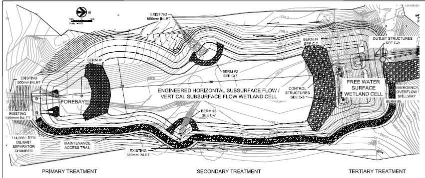
23 AURORA ESW LAYOUT
24 DESIGN BASIS Design for Water Quality Event Enhanced Water Quality Improvement to the 2- yr storm event 32.3 mm pptn, 71.5 ha catchment area Peak flow 2.76 m 3 /s, Volume: 4900 m 3 Design to Accommodate 100 Year Storm Design for Worse Influent Quality Effluent Quality Targets
25 EFFLUENT WATER QUALITY TARGETS (mg/l) TSS <10 BOD <0.5 TP 0.03 o-po TKN <0.3 NH 3 -N <0.03 Metals < PWQO Oil & Grease 0 E. coli < 2 log


26 REDUCED FOREBAY CONTAINING OGS VESSEL OGS at S. End of Forebay EW Cell Forebay Berm #1 Greatly Reduced Forebay With OGS Vessel Target: >60% TSS Removal Sections of Watergate OGS Vessel Forebay EW Cell


27 HSSF/VSSF EW CELL Berm #4 Two Control Structures in Berm #4 Forebay Upstream Berm #1 High Headspace EW Cell Filled with One Meter Thick Crushed Rock Substrate FWS CW Cell Downstream Runoff Flow ENGINEERED WETLAND CELL Target: A further 75% TSS removal + removal of BOD and NH 3 -N Effluent Collection Chambers Below Substrate at North End of EW Cell Berm #4 High Flow, VSSF Low Flow, HSSF EW Cell Cross-Section of Berm #4 North End of EW Cell FWS CW Cell

28 FWS CW CELL AT NORTH END OF ESW Berm #4 Berm #5 1 Control Structure Treated Effluent Discharge to Cold Water Stream EW CELL Free Water Surface Constructed Wetland Cell for Polishing Target: 95% TSS Removal in ESW

29 AURORA ESW DESIGN CRITERIA COMPARISON
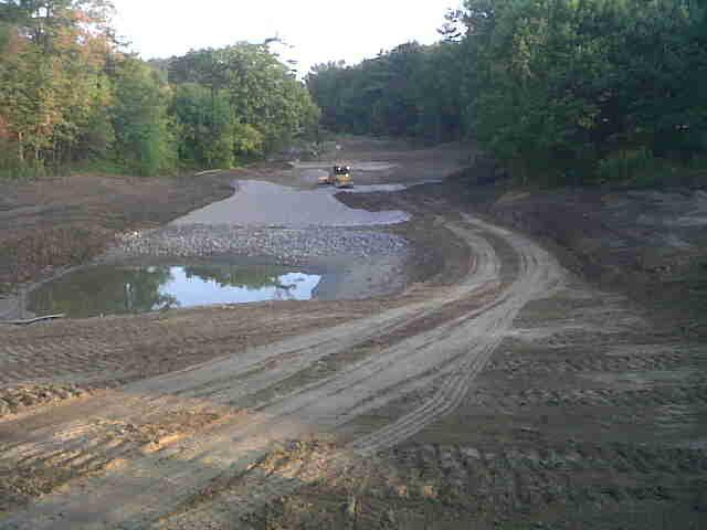
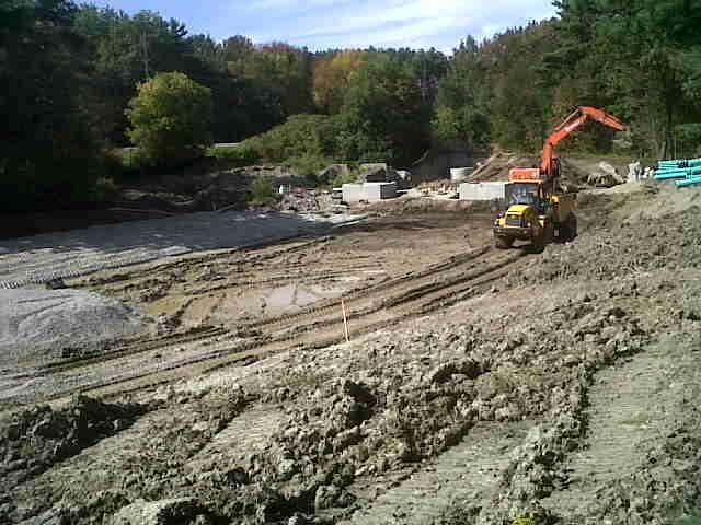
30 CONSTRUCTION
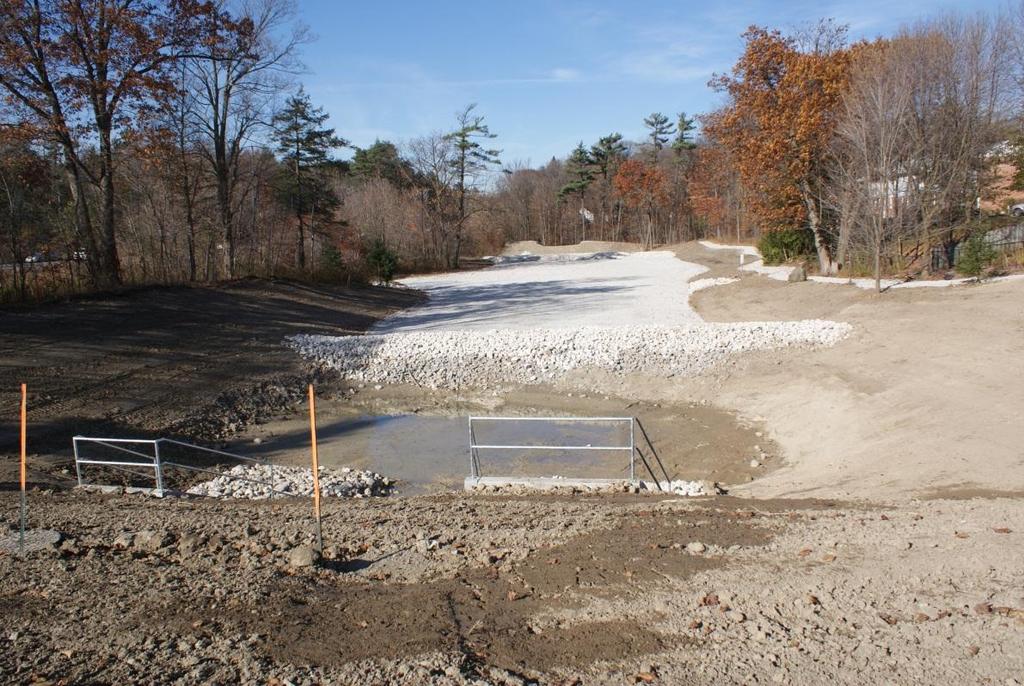
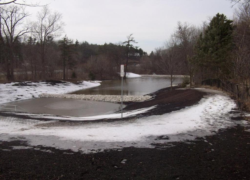
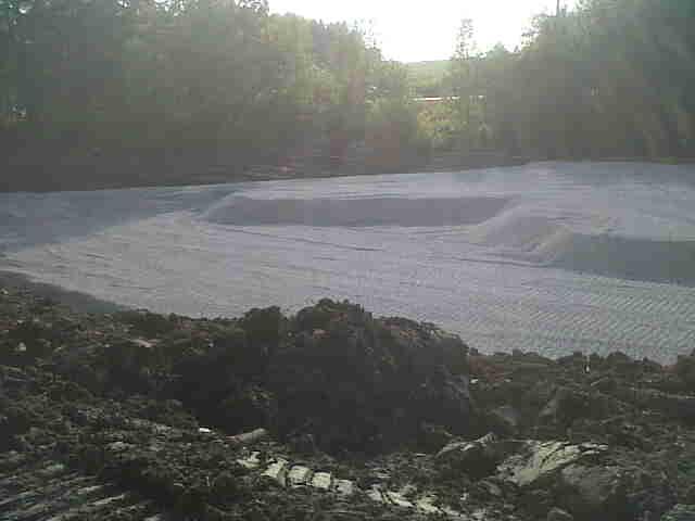
31 AS - CONSTRUCTED


32 ADVANTAGES OF ENGINEERED STORMWATER WETLANDS Manage Water Quantity & Water Quality Inexpensive to Construct & Operate Permanently Removes Pollutants Can Handle Varying Influent Quality Tolerant of Fluctuating Influent Flows Favorable Public Perception, Increased Aesthetics
 to ESW in")
33 WHERE TO FROM HERE Have completed MEA Class EA and Preliminary Design for Retrofit of Existing Wet Pond (Lincoln Pond) to ESW in Uxbridge


34 Thank You!