Production Engineering ALI NOORULDEEN
|
|
|
- Belinda Flynn
- 5 years ago
- Views:
Transcription
1 Production Engineering ALI NOORULDEEN 2014
2 Production System A complete oil or gas production system consists of: 1- Reservoir 2- Well 3- Separators 4- Pumps 5- Transportation pipelines The reservoir supplies wellbore with crude oil or gas. The well provides a path for the production fluid to flow from bottom hole to surface and offers a means to control the fluid production rate. The flow line leads the produced fluid to separators. The separators remove gas and water from the crude oil. Pumps and compressors are used to transport oil and gas through pipelines to sales points.
3 Well head Separator Gas Oil Water Wellbore Reservoir
4 Reservoir Hydrocarbon accumulations in geological traps can be classified as reservoir and field. A reservoir is a porous and permeable underground formation containing an individual bank of hydrocarbons confined by impermeable rock or water barriers and is characterized by a single natural pressure system. A field is an area that consists of one or more reservoirs all related to the same structural feature. Depending on the initial reservoir condition, hydrocarbon accumulations are classified as oil, gas condensate, and gas reservoirs. An oil that is at a pressure above its bubble-point pressure is called an under saturated oil because it can dissolve more gas at the given temperature. An oil that is at its bubble-point pressure is called a saturated oil because it can dissolve no more gas at the given temperature. Single (liquid)-phase flow prevails in an under saturated oil reservoir, where as two-phase (liquid oil and free gas) flow exists in a saturated oil reservoir.
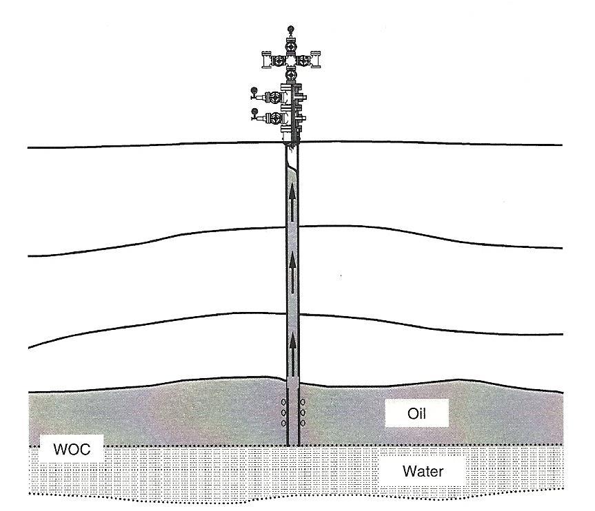
5 Wells in the same reservoir can fall into categories of oil, condensate, and gas wells depending on the producing gas oil ratio (GOR). as wells are wells with producing GOR being greater than 100,000 SCF/STB; condensate wells are those with producing GOR being less than 100,000 SCF/STB but greater than 5,000 SCF/STB; and wells with producing GOR being less than 5,000 SCF/STB are classified as oil wells. Oil reservoirs can be classified based on driving mechanism into: 1- Water drive reservoir: Two types of water drive reservoir: 1- Edge-water drive reservoir in which the oil is surrounded by water. The pressure of the reservoir in this case remains constant at its initial value above the bubble point pressure. Single phase fluid flow exists in the formation for maximum well productivity. 2- Bottom-water drive reservoir in which the oil is accumulated above a surface of ground. The pressure of reservoir can be maintained at its initial value also, but it water coning problem is more likely to occur with production time.
6
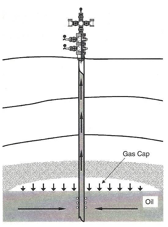
7 2- Gas Cap drive The driving mechanism in the reservoir is the expansion of the gas accumulated in the top of the reservoir above the oil surface. The pressure remains constant as the gas expands continuously. Gas breakthrough and production may be occurred if the oil production rate is not controlled very well. 3-Solution-gas drive Is also called volumetric drive or dissolved gas drive. The driving mechanism in this reservoir is the expansion of the dissolved gas in the liquid phase.
8
9 Wellbore Oil and gas wells are drilled like an upside-down telescope. The largediameter borehole section is at the top of the well. Each section is cased to the surface, or a liner is placed in the well that laps over the last casing in the well. Each casing or liner is cemented into the well (usually up to at least where the cement overlaps the previous cement job). The last casing in the well is the production casing (or production liner). Once the production casing has been cemented into the well, the production tubing is run into the well. Usually a packer is used near the bottom of the tubing to isolate the annulus between the outside of the tubing and the inside of the casing. Thus, the produced fluids are forced to move out of the perforation into the bottom of the well and then into the inside of the tubing.
10
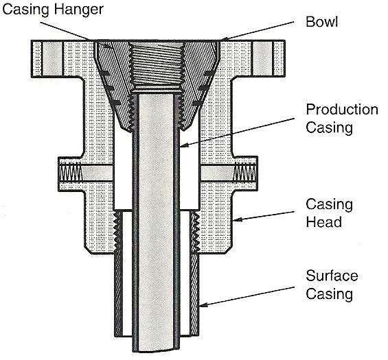
11 The wellhead is defined as the surface equipment set below the master valve. it includes casing heads and a tubing head. The casing head is threaded onto the surface casing. This can also be a flanged or studded connection. A casing head is a mechanical assembly used for hanging a casing string. Depending on casing programs in well drilling, several casing heads can be installed during well construction. The casing head has a bowl that supports the casing hanger. This casing hanger is threaded onto the top of the production casing. As in the case of the production tubing, the production casing is landed in tension so that the casing hanger actually supports the production casing. In a similar manner, the intermediate casing are supported by their respective casing hangers. All of these casing head arrangements are supported by the surface casing, which is in compression and cemented to the surface. A well completed with three casing strings has two casing heads. The uppermost casing head supports the production casing. The lowermost casing head sits on the surface casing.
12
13
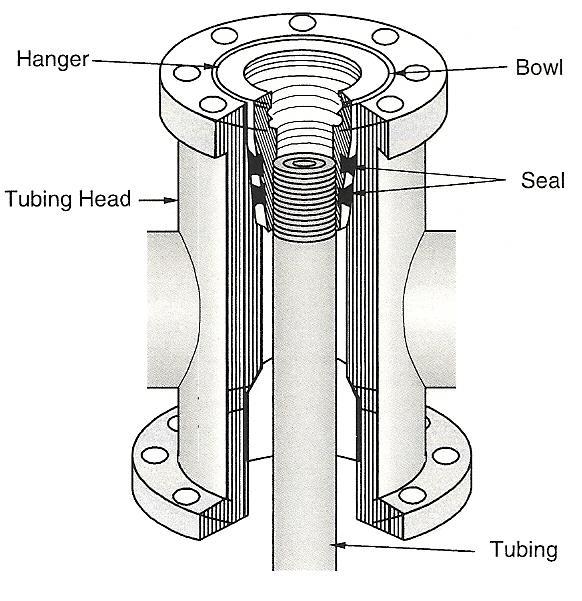
14 Most flowing wells are produced through a string of tubing run inside the production casing string. At the surface, the tubing is supported by the tubing head (the tubing head is used for hanging tubing string on the production casing head). The tubing head supports the tubing string at the surface (this tubing is landed on the tubing head so that it is in tension all the way down to the packer). The equipment at the top of the producing wellhead is called a Christmas tree and it is used to control flow. The Christmas tree is installed above the tubing head. The Christmas tree may have one flow outlet (a tee) or two flow outlets (a cross). The master valve is installed below the tee or cross. A Christmas tree consists of a main valve, wing valves, and a needle valve. These valves are used for closing the well when needed. At the top of the tee structure (on the top of the Christmas tree ), there is a pressure gauge that indicates the pressure in the tubing.
15
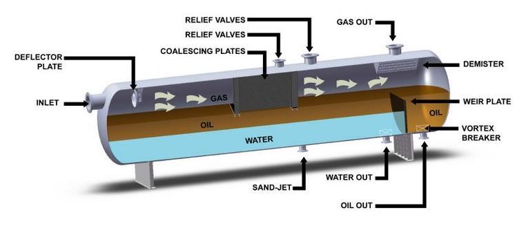
16 Separator The fluids produced from oil wells are normally complex mixtures of hundreds of different compounds. A typical oil well stream is a highvelocity, turbulent, constantly expanding mixture of gases and hydrocarbon liquids, intimately mixed with water vapor, free water, and sometimes solids. Three types of separators are generally available from manufacturers. Selection of separator type is based on several factors including characteristics of production steam to be treated, floor space availability at the facility site, transportation, and cost. 1-Horizontal separator: Horizontal separators are usually the first choice because of their low costs. Horizontal separators are almost widely used for high- GOR well streams, foaming well streams, or liquid-liquid separation.
17
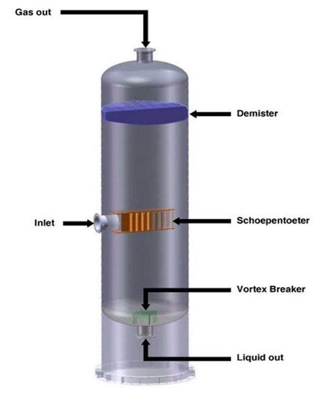
18 Horizontal separators are easier to skid-mount and service and require less piping for field connections. In horizontal separators, gas flows horizontally while liquid droplets fall toward the liquid surface. The moisture gas flows in the baffle surface and forms a liquid film that is drained away to the liquid section of the separator. The liquid-level control placement is more critical in a horizontal separator than in a vertical separator because of limited surge space. 2-Vertical separator: Vertical separators are often used to treat low to intermediate GOR well streams and streams with relatively large slugs of liquid. They handle greater slugs of liquid without carryover to the gas outlet, and the action of the liquid-level control is not as critical. Vertical separators occupy less floor space, which is important for facility sites such as those on offshore platforms where space is limited.
19
20 Because of the large vertical distance between the liquid level and the gas outlet, the chance for liquid to re-vaporize into the gas phase is limited. However, because of the natural upward flow of gas in a vertical separator against the falling droplets of liquid, adequate separator diameter is required. Vertical separators are more costly to fabricate and ship in skid-mounted assemblies. 3-Spherical separator: Spherical separators offer an inexpensive and compact means of separation arrangement. Because of their compact configurations, these types of separators have a very limited surge space and liquidsettling section. The placement and action of the liquid-level control in this type of separator is more critical.
21
22 Pumps and compressors After separation, oil is transported through pipelines to the sales points. Reciprocating piston pumps are used to provide mechanical energy required for the transportation. There are two types of piston strokes, the single-action piston stroke and the double-action piston stroke. The double-action stroke is used for duplex (two pistons) pumps. The single-action stroke is used for pumps with three pistons or greater (e.g., triplex pump). Compressors are used for providing gas pressure required to transport gas with pipelines and to lift oil in gas-lift operations. The compressors used in today s natural gas production industry fall into two distinct types: reciprocating and rotary compressor.
23 Transportation pipelines The first pipeline was built in the United States in 1859 to transport crude oil. Through the one and half century of pipeline operating practice, the petroleum industry has proven that pipelines are by far the most economical means of large-scale overland transportation for crude oil, natural gas, and their products, clearly superior to rail and truck transportation over competing routes, given large quantities to be moved on a regular basis. Transporting petroleum fluids with pipelines is a continuous and reliable operation. Pipelines have demonstrated an ability to adapt to a wide variety of environments including remote areas and hostile environments. With very minor exceptions, largely due to local peculiarities, most refineries are served by one or more pipelines, because of their superior flexibility to the alternatives. The pipelines are sized to handle the expected pressure and fluid flow. To ensure desired flow rate of product, pipeline size varies significantly from project to project. To contain the pressures, wall thicknesses of the pipelines range from ( in).
24 Productivity: Oil production rate of vertical well can be calculated using the following equation: q q k h P P B r r e e w wf o kh( P oil formation formation thickness, reservoir oil Bottom hole oil B o production, vis cos ity, formation wellbore ln( r e e / r w permeability, pressure, cp P ) radius, wf STB / flowing volume ft ) Day ft psi md pressure, factor, reservoir drainage radius, ft bbl psi / STB
25 HW: Q.3 Calculate and plot oil production rate corresponding to the following bottom hole flowing pressure: 250, 500, 750, 1000, 1250, 1500, 1750, 2000, 2250,2500, 2750, 3000, 3250, 3500, 3750 psi. Formation thickness (100 ft), reservoir drainage area (100 acres ), reservoir pressure (4000 psi), oil viscosity (2 cp), formation permeability (20 md), oil formation volume factor ( 1,15 bbl/stb) and wellbore radius (8 in). Q.4 For the formation in Q.3, calculate and plot reservoir pressure at r=100, 200, 300, 400, 500, 600, 700, 800, ft. The production rate (1500 STB/Day) and the bottom hole flowing pressure (2000 psi).
26 Productivity Index: Is the measurement of an oil well surface production rate corresponding to a certain pressure drop (Pe-Pwf). PI J P e q P w f kh B ln( r / r ) o e w PI J productivity index, STB / Day psi The highest productivity index, the most favorable condition.
27 Inflow performance relationship: A relationship describes oil flow rate flows from a reservoir to the wellbore corresponding to a certain bottom hole flowing pressure. It can be used to predict the production rates for different bottom hole flowing pressures. Vogel introduced the inflow performance relationship (IPR) as follow; q q q max max Pwf Pwf P 0.8 P max imum production open flow potential 2 rate or ( AOF ) of the the absolute well when Pwf 0 P average reservoir pressure
28 HW Q.5 A well is producing 500 STB/Day at 1000 psi bottom hole flowing pressure from a reservoir having average pressure (3000 and 2500 psi) and initial pressure (3500 psi). Plot the inflow performance curves.