Blockages in Cement Storage Silos
|
|
|
- Opal Owen
- 5 years ago
- Views:
Transcription


1 Blockages in Cement Storage Silos Loh Han Sen Territory Sales Manager AFCM 2015 Hanoi, April 21st to 24th, 2015


2 More than a 100 years of experience Efficient silo conception Storage capacity from 1.000m³ m³ More than 99% reclaim rate Applicable for bulk material such as cement, raw meal, alumina, fly ash, granulated slag etc. CLAUDIUS PETERS 100 years silo technology A 100 years experience for the benefit of our customers
3 Index 1. Introduction 2. Possible root causes for blockages 3. Evaluation/Recommendation

4 Introduction A problem in Cement Storage is the tendency of cement to form lumps: Problems with Discharge System? Problems with Material Stored? Problems with Silo Design? Problems with Construction? Cleaning of Silos are very labor intensive and root cause must be analyzed in order to avoid future occurrence. 4


5 Example Silo discharge comparison between two silo type EC silo: Chamber inlet : Opening area: approx. 0,8m x 1,8m In total approx. 24m² ME silo: Silo: Silo outlet Outlet :: Opening area: Area: app. approx. 0,3mx0,3m x 0,3m In total approx. 0,9m²


6 Positive Effect with very little dead zone 6

7 CaSO4 in the cement production Calcium Sulfate is added in small quantities to the cement during its manufacture to control the setting time. There are different occurrences of the Calcium Sulfate, these are shown in the following slides Depending on its status the CaSO4 contains between 20-0 % of combined water. Even though this is only a small amount that is added to the cement this can create unwanted side effects

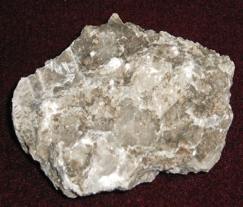
8 Gypsum Basis Gypsum in all forms, are phases of the system CaSO 4 / H 2 O, this is Calcium Sulfate in all hydration phases Impurities in Gypsum can have significant influence on the process, machine lifetime and product characteristics With additives and fillers it is possible to modify the characteristics of the finished product Gypsum typically is transparency ph-value smell taste toxic enflamable transparent, translucent 7 (neutral) none none no no Picture no. 8 Selenite


9 Colour of Gypsum Picture no. 9
 is the content of cristal bond water in the dry Gypsum or Stucco sample Picture no.")
10 Terms used for Stucco Production Free Moisture (FM) is the non cristal bond water of the gypsum and is based on the wet Gypsum Gypsum Purity (GP) is the content of Dihydrate in the dry Gypsum. Dry means no free water, but containing combined water Combined Water (CW) is the content of cristal bond water in the dry Gypsum or Stucco sample Picture no. 10
11 Chemical Structure CaSO 4 2H 2 O Contains 20,93% combined water Gypsum Dihydrate CaSO 4 ½H 2 O Contains 6,2% combined water Gypsum Hemihydrate CaSO 4 (A3) Contains no combined water Anhydrite Picture no. 11
12 Theoretical Combined Water M DH M HH = 172 g/mol 20,93 % CW = 145 g/mol 6,21 % CW M AH = 136 g/mol 0 % CW M H2O = 18 g/mol 20 0 Dihydrate Hemihydrate Anhydrite Combined H2O CaSO4 Picture no. 12
13 Index 1. Introduction 2. Possible Root causes for blockages 3. Evaluation/Recommendation

14 Possible causes of blockage problems Lump problems caused by moisture? The buildups are hardened material, which can not be easily destroyed, therefore there must be some water input: Direct water penetration? Water intake with air at over/under pressure valve and filter? Water intake with aeration air? Water intake with material? Problems assisted by discharge? If the material is stored for a long time in the silo (dead zones), then the cement will probably harden in this area
15 Direct water penetration Silo roof has been tested with direct water test? Lump formation is mainly at the walls? Determine if coatings are mainly in layers at the wall and not shaped as lumps in the center (what would indicate direct water intake) If silo has been filled already some time ago and cleaned afterwards, so moisture from building structure can be excluded. Conclusion: No direct water intake! Recommendation Nevetheless, check when emptied for direct water from the roof
16 Moisture diagram for air Absolute humidity is the total amount of water vapor present in a volume of air. Absolute humidity in the atmosphere ranges from near zero to roughly 30 g/m 3 when air is saturated at +30 O C At an air temperature of +30 O C and relative humidity of 80%, the absolute humidity is about 25 g/m. Dew point is about +26 O C Taken from: Siegel/ Pneumatische Förderung; Vogel Fachbuchverlag, 1984

17 Water intake at upper silo room? Exhaust Air 50 C Dewpoint at 26 C Ambient Air e.g.: 30 C 80% R.M. Contains 25g/m 3 water If the filter is running there is material feed to the silo Air is heated up Hot air can take more water Condensation can only take place if the air is cooled down below the dewpoint This might only be the case in the morning, when hot air might be cooled down at roof Conclusion: No severe water intake! Recommendation: When the feed is stopped no permanent run of the filter necessary. Then the max. moisture that can be released is the moisture in the air of upper silo room Negative pressure by the filter in the silo needs just to be sufficient to extract entered air

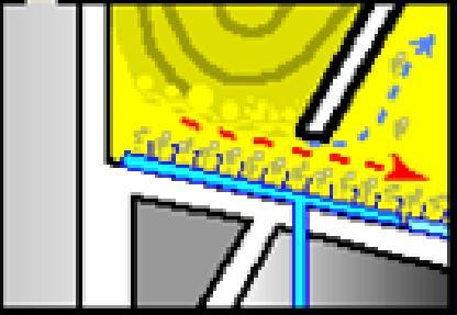
18 Route of Aeration Air Aeration air is travelling not through material to Silo top Only from aeration pads to Dedusting in chamber So material contact is only given with material, that is immediately discharged
19 Water Intake from Aeration Aeration is only running, if material is discharged Usually the material temperature is far above dew point, so no moisture from the air can be released to the product Usually material temperatures at the silo outlet will still be around C If the water from the aeration would be released to the material, this would be discharged with the material This amount of water would be very low Exhaust Air Air Intake: Max 12 kg of water/h, but appr 200t of material resulting in max moisture increase of 0,006% C Dewpoint at 26 C 30 C 80% Moisture Would contain 25g/m³ Conclusion No severe influence from Aeration air Recommendation Only run aeration, if there is discharge
20 Water from material? Behind mill the free moisture is measured. But the gypsum fraction of the product might still contain inherent moisture. The added gypsum to the grinding process, might, due to the short remaining time in the mill only partially calcined when it is leaving the mill. This remaining time in the mill is especially short when the mill has the roller press as pre-grinding in front. Only 50% of the combined water are released in the mill! The temperature of 105ºC behind mill is still enough to keep this process going. This first indication of that can be found in already started cloggings in bucket elevator, chutes and feeding aero slides on silo roof. In open aero slides still partially calcined lumps in agglomerated form have been found. The rest calcination will take place in the silo were the cement temperature is still above the critical point of 83 ºC. Then the steam is moving to colder areas of the material, where it is condensating and present as free water.


21 0.5 m VOLUME OF COATING ZONE AT SILO WALL V = 0,5m x 12m x π x 20m V = 380 m 3 20 m Ø 12 m 95ºC 30-40ºC 4 % GYPSUM IN CEMENT 20% COMBINED WATER IN GYPSUM IS FREE AFTER CALCINATION One silo filling contains 120 t of gypsum Therefore the amount of combined water in the gypsum would result in up to 12t water in one silo filling Not all of it will be released in the silo, but most of it will produce the lumps FORMED LUMPS WILL ALSO BE COLLECTED BY GRAVITY IN FRONT OF GATES IN CONE.

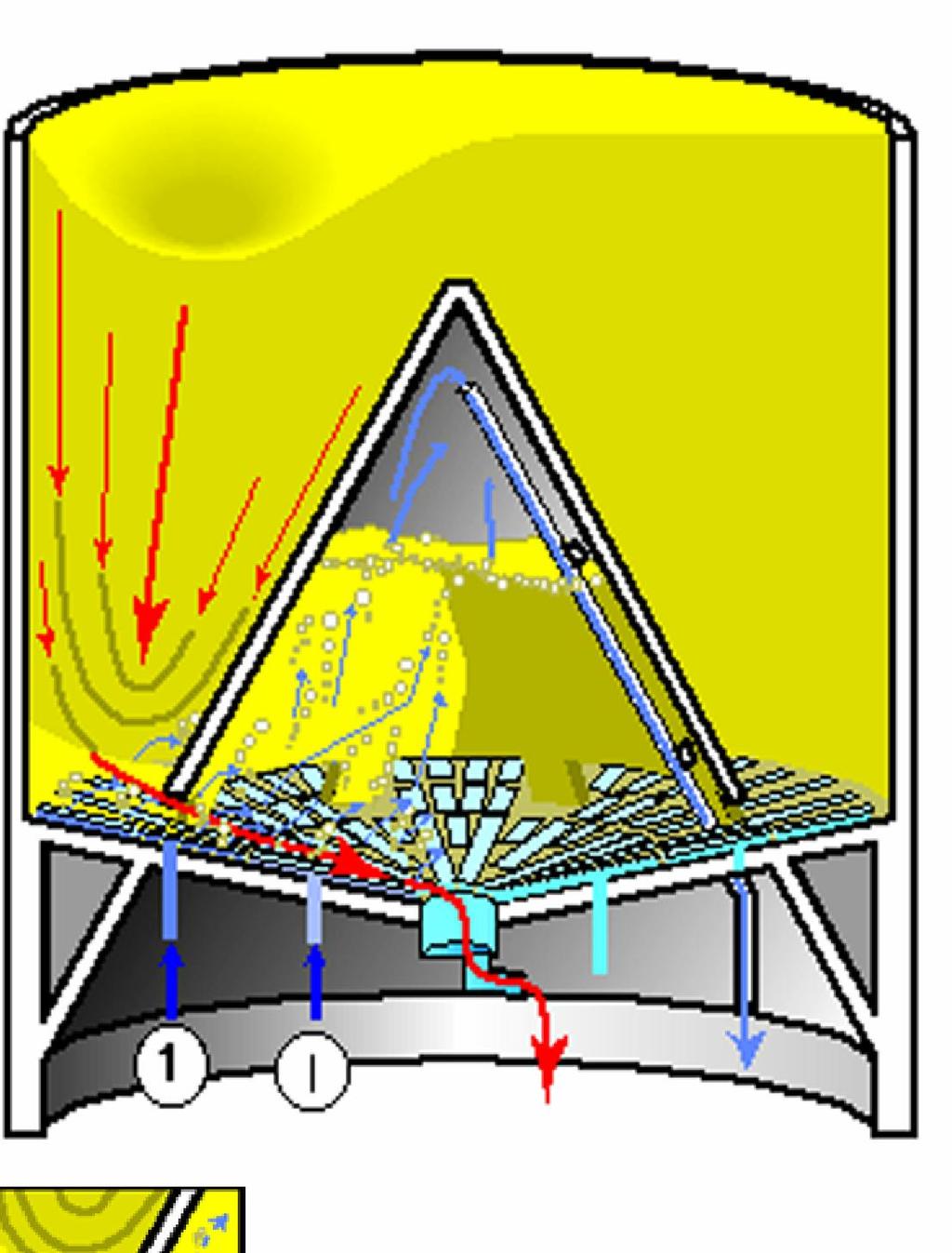
22 CEMENT 95 ºC 95º C 80º C 60º C SMALL COOLING EFFECT INSIDE CONE 80 ºC MAIN ZONE OF CONDENSATION AND LUMP FORMING MAIN COOLING EFFECT AT SILO WALL BY AMBIENT AIR 30 ºC 40 ºC 1 I LUMPS WILL BE COLLECTED AT LOWEST POINT BY GRAVITY AND IS BLOCKING THE GATES.
23 Material Samples
![Material Samples 06/10 Thermo gravimetric analysis/ Cement 1 Relative mass decrease [M - %] 0,9 0,8 0,7 0,6 0,5 0,4 0,3 0,2 Test No.](/docs-images/91/104812637/images/24-3.jpg "13637, Cement Malaysia Test No. 13630, Cement Germany Test No. 13404, Cement 20.03.")
24 Material Samples 06/10 Thermo gravimetric analysis/ Cement 1 Relative mass decrease [M - %] 0,9 0,8 0,7 0,6 0,5 0,4 0,3 0,2 Test No , Cement Malaysia Test No , Cement Germany Test No , Cement , Temperature [ C]
![Material Samples 06/10 Massenabnahmeverhalten in Abhängigkeit der Prüftemperatur 1 20 Relative mass decrease [M - %] 0,9 0,8 0,7 0,6 0,5 0,4 0,3 0,2 Test No. 13637, Cement Malaysia Test No.](/docs-images/91/104812637/images/25-3.jpg "13630, Cement Germany Test No. 13404, Cement 20.03.09 Test No.")
25 Material Samples 06/10 Massenabnahmeverhalten in Abhängigkeit der Prüftemperatur 1 20 Relative mass decrease [M - %] 0,9 0,8 0,7 0,6 0,5 0,4 0,3 0,2 Test No , Cement Malaysia Test No , Cement Germany Test No , Cement Test No , Gypsum Malaysia Relative mass decrease [M - %] 0, Temperature [ C]
![Dehydration of gypsum Duration/Temperature 120,0 105,0 Duration until mass is stable [min] 100,0 80,0 60,0 40,0](/docs-images/91/104812637/images/26-3.jpg "20,0 0,0 Test No.")
26 Dehydration of gypsum Duration/Temperature 120,0 105,0 Duration until mass is stable [min] 100,0 80,0 60,0 40,0 20,0 0,0 Test No , Gypsum Malaysia 58,3 31,9 16,8 7,9 2,0 2, Temperature [ C]
27 Index 1. Introduction 2. Possible Root causes for the blockages 3. Evaluation/Recommendation
28 Conclusion If after confirmation that there is no direct water intake: Root cause for the build ups in the silo is most probably the gypsum dehydration in the silo With the gypsum dehydration free water is available With this free water parts of the cement are hardened at the walls, there are coatings of up to 1m When the material level drops, some of these blocks fall down and later lead to blockages at the airslide The loose material can still partly be extracted pneumatically
29 Recommendation Mill Process: The gypsum shown here is quite slow in dehydration, therefore the mill adjustment on gypsum is not easy Replace parts of Dihydrate with Anhydrite or Hemihydrate In some plants that we know of the ratio of Anhydrite is roughly 50:50, but too much Anhydrite might influence the setting and strength of the concrete Adjust Water Spray High temperature in the mill with sufficient remaining time in the mill will lead to a more completed gypsum calcination in the mill The dew point behind mill should be monitored as otherwise the cement quality might be affected The utilization of a cement cooler might be an option as well Lower outlet temperature below 80 at the outlet will lead to less calcination in the silo Further literature is mentioned at: Hills, L; Water spray in cement finish mills; Portland Cement Association, R&D Serial No. 2889; Illinois 2006


30 Recommendation Silo Silo design has to be fit to its purposes. Some older design allows only funnel flow, but not for mass flow. Funnel flow leads to dead stock after some time. To achieve mass flow or nearly mass flow, you need to design the right opening size and right inclination. How to reach Mass Flow? Dead stock


31 Recomendation EC silo: Chamber inlet : Opening area: approx. 0,8m x 1,8m In total approx. 24m²
32 Recommendation Silo After cleaning and removal of the remaining cement inside the silo a silo inspection by CP is highly recommended This should include the condition of filter and dedusting system and the control system To reduce the amount of cement coating at the wall a friction reducing coating of the lower part of the silo cylinder up to cone height might be an option. By this means the cement can not create large build-ups in the lower area, where the upper cement coatings can rest onto. Some old silos have flat bottom, check if modification is an option for the silo but Structural design needs to be considered.

33 Coatings at silo wall TWO LAYERS OF HARDENED CEMENT AT SILO WALL Coatings start building up from the bottom New layers build up on top of the old layers Appr. 1m -1,5 m thickness INCREASED HARDENED LAYER THICKNESS AT SILO WALL FROM TOP TO BOTTOM.
34 Index 1. Introduction 2. Possible Root causes for the blockages 3. Evaluation/Recommendation
35 CLAUDIUS PETERS silotypes - Inspection chamber technology - IC Features Advantages Maximum storage capacity Small installation height Installation of equipment in the chamber Discharge capacity up to 1,000 t/h Silo diameter from m 2 or more standard discharges Relclaim discharge rate > 99% low energy needs Inspection by ICchamber Use of ring chamber f Saving silo corpus Small installation height f Short loading and unloading time Optimal utilization of spaces High flexibility f Purity of variety f Saving operation costs During operation

36 CLAUDIUS PETERS silotypes - Inspection chamber technology - IC Ring Channel Inspection 36


37 Claudius Peters Gravity separator Grid prevents throughput of lumps Separation of lumps lead to high service reliability and availability Discharge via manual or automatically via pneumatic flaps


38 Claudius Peters Lump Breaker Features Available for all aeroslides and silo outlets Mass flow of cement up to 1000 t/h Designed for material temperature up to 180 C Motor power: 0,75 KW at 25 min -1 High wear resistant materials for crusher and grid Easy maintenance
39 Silo Discharge with Lump Breaker Lump Breaker, horizontal Lump Breaker, vertical

40 The Thank Beach picture You! 40