Astra Engineering LLC
|
|
|
- Victor Garrison
- 5 years ago
- Views:
Transcription
1 Astra Engineering LLC!"#$#% &'( ) *) ) *)* +## ) ',#$$+-."$% "#"-",-/$+ 0 ) )1'(0 23** ) 243 5* )3 9**!:;2<3 3$#$=97*9>4?)3* 973''!"$#%=4? *9> %-2/- 3*$/A 2 13* *-* 2!!2 3*!*!2 * = >B27** 3@+ 53! * 7887 E. Belleview Avenue, Suite 1100, Englewood, Colorado Ph
2 **+A* **3 832 *** /A 2,!2!!! 3**!* 3?2!23* **5*!='#%#>2?*!-!2!324C9 49 2?** 2*(3* 3?* *32 * 2!33**5$( B!2*!3?2 333** 2 7 2=$97<> * 2* (* 3!-!C=#.*3** 3* * 3!-!C$C" =#>%97<**,97<2*3*-!*32 *!-##- =***5> '!-!'B3!-!C.=#, * 3*3>2* -!*3 2* *-**5##-!-!C=##,* 3*> -!*32* *- ##-**5##-!-!=##/*2 >32 3*!-!)=#,* 2 >=+ >!-!)$=#$ *>@
3 32?*2 53?*2-2!2!*3 3* 3##-**3!*23!8 3*2**2* 2D * * :!33! 73 E! 3* ** *4 35*6 789= )>!2** *3?)3* "#"-$"-"%%.
4 ))7*!33 5* 2!33* *:!33F!3: 23*!! ))7*333! )) 7*FF3!** 3:** 7F) *7 *** 3G33 0 HHHHHHHHHHHHHHHHHHHHHHHHHHHHHH ))7* HHHHHHHHHHHHHHHHHHHHHHHHHHH HHHHHHHHHHHHHHHHHHHHHHHHHHHHHH 7! 83 I:!*=*>333 5* 2**!=* > 2* * )37!7 :* *!7:!33! HHHHHHHHHHHHHHHHHHHHHHHHHHHHHHHHHHHHHHHHH 373 $""/
5
6 Astra Engineering Inc. The Learning Center Thornton, CO Site 1.11 acres Proposed Composite Coefficients of Runoff Cover type Area (sf) Imperviousness Landscape 17,479 2% Roof 10,000 90% Playground 5,206 75% Concrete 15,715 90% 48,400 Proposed Imperviousness I= 56.6% B acres 171 Proposed Composite Coefficients of Runoff Cover type Area (sf) Imperviousness Landscape 10,830 2% Roof 0 90% Playground 5,206 75% Concrete 1,175 90% 17,1 Proposed Imperviousness I= 30.1% c5 = c100=! c5 = c100= " B acres 7710 Proposed Composite Coefficients of Runoff Cover type Area (sf) Imperviousness Landscape 460 2% Roof 0 90% Playground 0 75% Concrete 7,250 90% 7,710 Proposed Imperviousness I= 84.7% c5 = " c100=
7 B acres 3320 Proposed Composite Coefficients of Runoff Cover type Area (sf) Imperviousness Landscape 400 2% Roof 0 90% Playground 0 75% Concrete 2,920 90% 3,320 Proposed Imperviousness I= 79.4% c5 = c100= # C acres 3156 Proposed Composite Coefficients of Runoff Cover type Area (sf) Imperviousness Landscape 1,846 2% Roof 0 90% Playground 0 75% Concrete 1,310 90% 3,156 Proposed Imperviousness I= 38.5% c5 = # c100= " D acres 7642 Proposed Composite Coefficients of Runoff Cover type Area (sf) Imperviousness Landscape 6,882 2% Roof 0 90% Playground 0 75% Concrete % 7,642 Proposed Imperviousness I= 10.8% c5 = c100=
8 STANDARD FORM SF - 1 TIME OF CONCENTRATION PROJECT: Thornton TLE DATE: 7/26/2016 t c = t i + t t INITIAL / OVERLAND TRAVEL TIME t c CHECK FINAL REMARKS TIME (t i ) (t t ) (URBANIZED BASINS) t c TOTAL tc=(l/180) AREA C BASIN 5 LENGTH SLOPE ti LENGTH SLOPE VEL. tt COMP. LENGTH +10 DESIGN. Ac Ft % Min Ft % FPS Min tc (Ft) Min Min (2) (3) (4) (5) (6) (7) (8) (9) (10) (11) (12) (13) (14) Use 5.0 minutes for all proposed basins
9 CALCULATED BY: CLE STANDARD FORM SF -2 PROJECT: TLE DATE: 10/19/2016 STORM DRAINAGE SYSTEM DESIGN Thornton (RATIONAL METHOD PROCEDURE) DIRECT RUNOFF TOTAL RUNOFF STREET PIPE TRAVEL TIME DESIGN STORM: 5 YR MAJOR STORM: 100YR DESIGN POINT AREA DESIGN AREA (AC) RUNOFF COEFF tc (MIN) C. A (AC) I IN / HR Q (CFS) tc (MIN) SUM C. A (AC) I IN / HR Q (CFS) SLOPE (%) STREET FLOW(CFS) DESIGN FLOW(CFS) SLOPE (%) PIPE SIZE LENGTH (FT) VELOCITY (FPS) tt (MIN) REMARKS (1) (2) (3) (4) (5) (6) (7) (8) (9) (10) (11) (12) (13) (14) (15) (16) (17) (18) (19) (20) () () 5-year!"#$% &'('$)*+,#*-*,.., " " /( +,#%, " " 1.16
 Maximum Allowable Width for Spread Behind Curb T BACK = 2.")
10 ALLOWABLE CAPACITY FOR ONE-HALF OF STREET (Minor & Major Storm) Project: Inlet ID: (Based on Regulated Criteria for Maximum Allowable Flow Depth and Spread) Enter Your Project Name Here Inlet 1-B1 Gutter Geometry (Enter data in the blue cells) Maximum Allowable Width for Spread Behind Curb T BACK = 2.0 ft Side Slope Behind Curb (leave blank for no conveyance credit behind curb) S BACK = ft/ft Manning's Roughness Behind Curb (typically between and 0.020) n BACK = Height of Curb at Gutter Flow Line H CURB = 6.00 inches Distance from Curb Face to Street Crown T CROWN = 13.0 ft Gutter Width W = 2.00 ft Street Transverse Slope S X = ft/ft Gutter Cross Slope (typically 2 inches over 24 inches or ft/ft) S W = ft/ft Street Longitudinal Slope - Enter 0 for sump condition S O = ft/ft Manning's Roughness for Street Section (typically between and 0.020) n STREET = Minor Storm Major Storm Max. Allowable Spread for Minor & Major Storm T MAX = ft Max. Allowable Depth at Gutter Flowline for Minor & Major Storm d MAX = inches Allow Flow Depth at Street Crown (leave blank for no) check = yes Maximum Capacity for 1/2 Street based On Allowable Spread Minor Storm Major Storm Water Depth without Gutter Depression (Eq. ST-2) y = inches Vertical Depth between Gutter Lip and Gutter Flowline (usually 2") d C = inches Gutter Depression (d C - (W * S x * 12)) a = inches Water Depth at Gutter Flowline d = inches Allowable Spread for Discharge outside the Gutter Section W (T - W) T X = ft Gutter Flow to Design Flow Ratio by FHWA HEC- method (Eq. ST-7) E O = Discharge outside the Gutter Section W, carried in Section T X Q X = cfs Discharge within the Gutter Section W (Q T - Q X ) Q W = cfs Discharge Behind the Curb (e.g., sidewalk, driveways, & lawns) Q BACK = cfs Maximum Flow Based On Allowable Spread Q T = SUMP SUMP cfs Flow Velocity within the Gutter Section V = fps V*d Product: Flow Velocity times Gutter Flowline Depth V*d = Maximum Capacity for 1/2 Street based on Allowable Depth Minor Storm Major Storm Theoretical Water Spread T TH = ft Theoretical Spread for Discharge outside the Gutter Section W (T - W) T X TH = ft Gutter Flow to Design Flow Ratio by FHWA HEC- method (Eq. ST-7) E O = Theoretical Discharge outside the Gutter Section W, carried in Section T X TH Q X TH = cfs Actual Discharge outside the Gutter Section W, (limited by distance T CROWN ) Q X = cfs Discharge within the Gutter Section W (Q d - Q X ) Q W = cfs Discharge Behind the Curb (e.g., sidewalk, driveways, & lawns) Q BACK = cfs Total Discharge for Major & Minor Storm (Pre-Safety Factor) Q = cfs Average Flow Velocity Within the Gutter Section V = fps V*d Product: Flow Velocity Times Gutter Flowline Depth V*d = Slope-Based Depth Safety Reduction Factor for Major & Minor (d > 6") Storm R = SUMP SUMP Max Flow Based on Allowable Depth (Safety Factor Applied) Q d = SUMP SUMP cfs Resultant Flow Depth at Gutter Flowline (Safety Factor Applied) d = inches Resultant Flow Depth at Street Crown (Safety Factor Applied) d CROWN = inches MINOR STORM Allowable Capacity is based on Depth Criterion Minor Storm Major Storm MAJOR STORM Allowable Capacity is based on Depth Criterion Q allow = SUMP SUMP cfs Copy of UD-Inlet_v4.03-Inlet 2 - O1 +B4, Inlet 1-B1 10/19/2016, 9:03 AM
11 INLET IN A SUMP OR SAG LOCATION H-Curb W W P H-Vert Lo (C) W o Lo (G) Design Information (Input) MINOR MAJOR CDOT Type R Curb Opening Type of Inlet Type = CDOT Type R Curb Opening Local Depression (additional to continuous gutter depression 'a' from 'Q-Allow') a local = inches Number of Unit Inlets (Grate or Curb Opening) No = 1 1 Water Depth at Flowline (outside of local depression) Ponding Depth = inches Grate Information MINOR MAJOR Override Depths Length of a Unit Grate L o (G) = N/A N/A feet Width of a Unit Grate W o = N/A N/A feet Area Opening Ratio for a Grate (typical values ) A ratio = N/A N/A Clogging Factor for a Single Grate (typical value ) C f (G) = N/A N/A Grate Weir Coefficient (typical value ) C w (G) = N/A N/A Grate Orifice Coefficient (typical value ) C o (G) = N/A N/A Curb Opening Information MINOR MAJOR Length of a Unit Curb Opening L o (C) = feet Height of Vertical Curb Opening in Inches H vert = inches Height of Curb Orifice Throat in Inches H throat = inches Angle of Throat (see USDCM Figure ST-5) Theta = degrees Side Width for Depression Pan (typically the gutter width of 2 feet) W p = feet Clogging Factor for a Single Curb Opening (typical value 0.10) C f (C) = Curb Opening Weir Coefficient (typical value ) C w (C) = Curb Opening Orifice Coefficient (typical value ) C o (C) = Low Head Performance Reduction (Calculated) MINOR MAJOR Depth for Grate Midwidth d Grate = N/A N/A ft Depth for Curb Opening Weir Equation d Curb = ft Combination Inlet Performance Reduction Factor for Long Inlets RF Combination = Curb Opening Performance Reduction Factor for Long Inlets RF Curb = Grated Inlet Performance Reduction Factor for Long Inlets RF Grate = N/A N/A MINOR MAJOR Total Inlet Interception Capacity (assumes clogged condition) Q a = cfs Inlet Capacity IS GOOD for Minor and Major Storms(>Q PEAK) Q PEAK REQUIRED = cfs Copy of UD-Inlet_v4.03-Inlet 2 - O1 +B4, Inlet 1-B1 10/19/2016, 9:00 AM
12 ALLOWABLE CAPACITY FOR ONE-HALF OF STREET (Minor & Major Storm) (Based on Regulated Criteria for Maximum Allowable Flow Depth and Spread) Thornton TLE Inlet 2 Gutter Geometry (Enter data in the blue cells) Maximum Allowable Width for Spread Behind Curb T BACK = 2.0 ft Side Slope Behind Curb (leave blank for no conveyance credit behind curb) S BACK = ft/ft Manning's Roughness Behind Curb (typically between and 0.020) n BACK = Height of Curb at Gutter Flow Line H CURB = 6.00 inches Distance from Curb Face to Street Crown T CROWN = 13.0 ft Gutter Width W = 2.00 ft Street Transverse Slope S X = ft/ft Gutter Cross Slope (typically 2 inches over 24 inches or ft/ft) S W = ft/ft Street Longitudinal Slope - Enter 0 for sump condition S O = ft/ft Manning's Roughness for Street Section (typically between and 0.020) n STREET = Minor Storm Major Storm Max. Allowable Spread for Minor & Major Storm T MAX = ft Max. Allowable Depth at Gutter Flowline for Minor & Major Storm d MAX = inches Allow Flow Depth at Street Crown (leave blank for no) check = yes Maximum Capacity for 1/2 Street based On Allowable Spread Minor Storm Major Storm Water Depth without Gutter Depression (Eq. ST-2) y = inches Vertical Depth between Gutter Lip and Gutter Flowline (usually 2") d C = inches Gutter Depression (d C - (W * S x * 12)) a = inches Water Depth at Gutter Flowline d = inches Allowable Spread for Discharge outside the Gutter Section W (T - W) T X = ft Gutter Flow to Design Flow Ratio by FHWA HEC- method (Eq. ST-7) E O = Discharge outside the Gutter Section W, carried in Section T X Q X = cfs Discharge within the Gutter Section W (Q T - Q X ) Q W = cfs Discharge Behind the Curb (e.g., sidewalk, driveways, & lawns) Q BACK = cfs Maximum Flow Based On Allowable Spread Q T = SUMP SUMP cfs Flow Velocity within the Gutter Section V = fps V*d Product: Flow Velocity times Gutter Flowline Depth V*d = Maximum Capacity for 1/2 Street based on Allowable Depth Minor Storm Major Storm Theoretical Water Spread T TH = ft Theoretical Spread for Discharge outside the Gutter Section W (T - W) T X TH = ft Gutter Flow to Design Flow Ratio by FHWA HEC- method (Eq. ST-7) E O = Theoretical Discharge outside the Gutter Section W, carried in Section T X TH Q X TH = cfs Actual Discharge outside the Gutter Section W, (limited by distance T CROWN ) Q X = cfs Discharge within the Gutter Section W (Q d - Q X ) Q W = cfs Discharge Behind the Curb (e.g., sidewalk, driveways, & lawns) Q BACK = cfs Total Discharge for Major & Minor Storm (Pre-Safety Factor) Q = cfs Average Flow Velocity Within the Gutter Section V = fps V*d Product: Flow Velocity Times Gutter Flowline Depth V*d = Slope-Based Depth Safety Reduction Factor for Major & Minor (d > 6") Storm R = SUMP SUMP Max Flow Based on Allowable Depth (Safety Factor Applied) Q d = SUMP SUMP cfs Resultant Flow Depth at Gutter Flowline (Safety Factor Applied) d = inches Resultant Flow Depth at Street Crown (Safety Factor Applied) d CROWN = inches MINOR STORM Allowable Capacity is based on Depth Criterion Minor Storm Major Storm MAJOR STORM Allowable Capacity is based on Depth Criterion Q allow = SUMP SUMP cfs Copy of UD-Inlet_v4.03-Inlet 2 - O1 +B4, Inlet 2 11/30/2016, 12:03 PM
13 INLET IN A SUMP OR SAG LOCATION H-Curb W W P H-Vert Lo (C) Wo Lo (G) Design Information (Input) MINOR MAJOR CDOT Type R Curb Opening Type of Inlet Type = CDOT Type R Curb Opening Local Depression (additional to continuous gutter depression 'a' from 'Q-Allow') a local = inches Number of Unit Inlets (Grate or Curb Opening) No = 2 2 Water Depth at Flowline (outside of local depression) Ponding Depth = inches Grate Information MINOR MAJOR Override Depths Length of a Unit Grate L o (G) = N/A N/A feet Width of a Unit Grate W o = N/A N/A feet Area Opening Ratio for a Grate (typical values ) A ratio = N/A N/A Clogging Factor for a Single Grate (typical value ) C f (G) = N/A N/A Grate Weir Coefficient (typical value ) C w (G) = N/A N/A Grate Orifice Coefficient (typical value ) C o (G) = N/A N/A Curb Opening Information MINOR MAJOR Length of a Unit Curb Opening L o (C) = feet Height of Vertical Curb Opening in Inches H vert = inches Height of Curb Orifice Throat in Inches H throat = inches Angle of Throat (see USDCM Figure ST-5) Theta = degrees Side Width for Depression Pan (typically the gutter width of 2 feet) W p = feet Clogging Factor for a Single Curb Opening (typical value 0.10) C f (C) = Curb Opening Weir Coefficient (typical value ) C w (C) = Curb Opening Orifice Coefficient (typical value ) C o (C) = Low Head Performance Reduction (Calculated) MINOR MAJOR Depth for Grate Midwidth d Grate = N/A N/A ft Depth for Curb Opening Weir Equation d Curb = ft Combination Inlet Performance Reduction Factor for Long Inlets RF Combination = Curb Opening Performance Reduction Factor for Long Inlets RF Curb = Grated Inlet Performance Reduction Factor for Long Inlets RF Grate = N/A N/A MINOR MAJOR Total Inlet Interception Capacity (assumes clogged condition) Q a = cfs Inlet Capacity IS GOOD for Minor and Major Storms(>Q PEAK) Q PEAK REQUIRED = cfs Copy of UD-Inlet_v4.03-Inlet 2 - O1 +B4, Inlet 2 11/30/2016, 12:05 PM
14 ALLOWABLE CAPACITY FOR ONE-HALF OF STREET (Minor & Major Storm) (Based on Regulated Criteria for Maximum Allowable Flow Depth and Spread) Thornton TLE Inlet 3-B5 Gutter Geometry (Enter data in the blue cells) Maximum Allowable Width for Spread Behind Curb T BACK = 2.0 ft Side Slope Behind Curb (leave blank for no conveyance credit behind curb) S BACK = ft/ft Manning's Roughness Behind Curb (typically between and 0.020) n BACK = Height of Curb at Gutter Flow Line H CURB = 6.00 inches Distance from Curb Face to Street Crown T CROWN = 13.0 ft Gutter Width W = 2.00 ft Street Transverse Slope S X = ft/ft Gutter Cross Slope (typically 2 inches over 24 inches or ft/ft) S W = ft/ft Street Longitudinal Slope - Enter 0 for sump condition S O = ft/ft Manning's Roughness for Street Section (typically between and 0.020) n STREET = Minor Storm Major Storm Max. Allowable Spread for Minor & Major Storm T MAX = ft Max. Allowable Depth at Gutter Flowline for Minor & Major Storm d MAX = inches Allow Flow Depth at Street Crown (leave blank for no) check = yes Maximum Capacity for 1/2 Street based On Allowable Spread Minor Storm Major Storm Water Depth without Gutter Depression (Eq. ST-2) y = inches Vertical Depth between Gutter Lip and Gutter Flowline (usually 2") d C = inches Gutter Depression (d C - (W * S x * 12)) a = inches Water Depth at Gutter Flowline d = inches Allowable Spread for Discharge outside the Gutter Section W (T - W) T X = ft Gutter Flow to Design Flow Ratio by FHWA HEC- method (Eq. ST-7) E O = Discharge outside the Gutter Section W, carried in Section T X Q X = cfs Discharge within the Gutter Section W (Q T - Q X ) Q W = cfs Discharge Behind the Curb (e.g., sidewalk, driveways, & lawns) Q BACK = cfs Maximum Flow Based On Allowable Spread Q T = SUMP SUMP cfs Flow Velocity within the Gutter Section V = fps V*d Product: Flow Velocity times Gutter Flowline Depth V*d = Maximum Capacity for 1/2 Street based on Allowable Depth Minor Storm Major Storm Theoretical Water Spread T TH = ft Theoretical Spread for Discharge outside the Gutter Section W (T - W) T X TH = ft Gutter Flow to Design Flow Ratio by FHWA HEC- method (Eq. ST-7) E O = Theoretical Discharge outside the Gutter Section W, carried in Section T X TH Q X TH = cfs Actual Discharge outside the Gutter Section W, (limited by distance T CROWN ) Q X = cfs Discharge within the Gutter Section W (Q d - Q X ) Q W = cfs Discharge Behind the Curb (e.g., sidewalk, driveways, & lawns) Q BACK = cfs Total Discharge for Major & Minor Storm (Pre-Safety Factor) Q = cfs Average Flow Velocity Within the Gutter Section V = fps V*d Product: Flow Velocity Times Gutter Flowline Depth V*d = Slope-Based Depth Safety Reduction Factor for Major & Minor (d > 6") Storm R = SUMP SUMP Max Flow Based on Allowable Depth (Safety Factor Applied) Q d = SUMP SUMP cfs Resultant Flow Depth at Gutter Flowline (Safety Factor Applied) d = inches Resultant Flow Depth at Street Crown (Safety Factor Applied) d CROWN = inches MINOR STORM Allowable Capacity is based on Depth Criterion Minor Storm Major Storm MAJOR STORM Allowable Capacity is based on Depth Criterion Q allow = SUMP SUMP cfs Copy of UD-Inlet_v4.03-Inlet 2 - O1 +B4, Inlet 3-B5 11/30/2016, 12:01 PM
15 INLET IN A SUMP OR SAG LOCATION H-Curb W W P H-Vert Lo (C) W o Lo (G) Design Information (Input) MINOR MAJOR CDOT Type R Curb Opening Type of Inlet Type = CDOT Type R Curb Opening Local Depression (additional to continuous gutter depression 'a' from 'Q-Allow') a local = inches Number of Unit Inlets (Grate or Curb Opening) No = 1 1 Water Depth at Flowline (outside of local depression) Ponding Depth = inches Grate Information MINOR MAJOR Override Depths Length of a Unit Grate L o (G) = N/A N/A feet Width of a Unit Grate W o = N/A N/A feet Area Opening Ratio for a Grate (typical values ) A ratio = N/A N/A Clogging Factor for a Single Grate (typical value ) C f (G) = N/A N/A Grate Weir Coefficient (typical value ) C w (G) = N/A N/A Grate Orifice Coefficient (typical value ) C o (G) = N/A N/A Curb Opening Information MINOR MAJOR Length of a Unit Curb Opening L o (C) = feet Height of Vertical Curb Opening in Inches H vert = inches Height of Curb Orifice Throat in Inches H throat = inches Angle of Throat (see USDCM Figure ST-5) Theta = degrees Side Width for Depression Pan (typically the gutter width of 2 feet) W p = feet Clogging Factor for a Single Curb Opening (typical value 0.10) C f (C) = Curb Opening Weir Coefficient (typical value ) C w (C) = Curb Opening Orifice Coefficient (typical value ) C o (C) = Grate Flow Analysis (Calculated) MINOR MAJOR Clogging Coefficient for Multiple Units Coef = N/A N/A Clogging Factor for Multiple Units Clog = N/A N/A Grate Capacity as a Weir (based on Modified HEC Method) MINOR MAJOR Interception without Clogging Q wi = N/A N/A cfs Interception with Clogging Q wa = N/A N/A cfs Grate Capacity as a Orifice (based on Modified HEC Method) MINOR MAJOR Interception without Clogging Q oi = N/A N/A cfs Interception with Clogging Q oa = N/A N/A cfs Grate Capacity as Mixed Flow MINOR MAJOR Interception without Clogging Q mi = N/A N/A cfs Interception with Clogging Q ma = N/A N/A cfs Resulting Grate Capacity (assumes clogged condition) Q Grate = N/A N/A cfs Curb Opening Flow Analysis (Calculated) MINOR MAJOR Clogging Coefficient for Multiple Units Coef = Clogging Factor for Multiple Units Clog = Curb Opening as a Weir (based on Modified HEC Method) MINOR MAJOR Interception without Clogging Q wi = cfs Interception with Clogging Q wa = cfs Curb Opening as an Orifice (based on Modified HEC Method) MINOR MAJOR Interception without Clogging Q oi = cfs Interception with Clogging Q oa = cfs Curb Opening Capacity as Mixed Flow MINOR MAJOR Interception without Clogging Q mi = cfs Interception with Clogging Q ma = cfs Resulting Curb Opening Capacity (assumes clogged condition) Q Curb = cfs Resultant Street Conditions MINOR MAJOR Total Inlet Length L = feet Resultant Street Flow Spread (based on sheet Q-Allow geometry) T = ft Resultant Flow Depth at Street Crown d CROWN = inches Low Head Performance Reduction (Calculated) MINOR MAJOR Depth for Grate Midwidth d Grate = N/A N/A ft Depth for Curb Opening Weir Equation d Curb = ft Combination Inlet Performance Reduction Factor for Long Inlets RF Combination = Curb Opening Performance Reduction Factor for Long Inlets RF Curb = Grated Inlet Performance Reduction Factor for Long Inlets RF Grate = N/A N/A MINOR MAJOR Total Inlet Interception Capacity (assumes clogged condition) Q a = cfs Inlet Capacity IS GOOD for Minor and Major Storms(>Q PEAK) Q PEAK REQUIRED = cfs Copy of UD-Inlet_v4.03-Inlet 2 - O1 +B4, Inlet 3-B5 11/30/2016, 12:02 PM
16 Pipe size and riprap!"###!$ %&'( &#!)!*"###!$

17 !"###!$ %&'+( &#!)!*"###!$
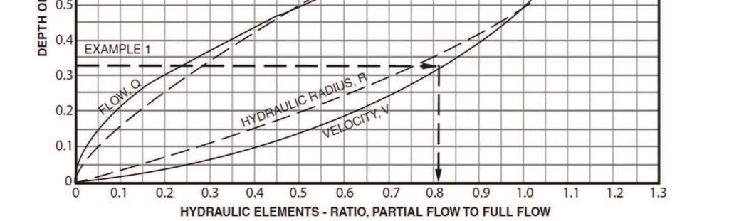
18 ,!) -.%.+.%.+ /&0&1!)%23!$ )&4( 3"&($3' Yt/D = 0.40 Q/D 1.5 = 5.8 Use Type L riprap Extent of riprap,!) -.%+.+.%.+ /&0&1!)%23!$ )&4( 3"&($3'

 18\" RCP@0.5% (BY OTHERS) 52 23 52 5. C.O.INLET (BY OTHERS) FL.")
 58 18 B3 B1 58 0.11.75.83 0.40.30.57 C1 19 2 3 19 20 17 5-YR RUNOFF (cfs) 100-YR RUNOFF 0.40 0.56 2.08 0.11/0.")
19 DRAINAGE PLAN DRAINAGE LEGEND DRAINAGE BOUNDARY BASIN DESIGNATION 5-YEAR RUNOFF COEFFICIENT YEAR RUNOFF COEFFICIENT DIRECTIONAL FLOW ARROW EXISTING CONTOUR PROPOSED CONTOUR PROPOSED SPOT ELEVATION DETENTION AREA 5-YR ASSUMED* Q = 2.8 CFS 5-YR ACTUAL Q = 2.7 CFS (PIPE) 100-YR ASSUMED* Q = 6.2 CFS 100-YR ACTUAL Q = 6.4 CFS(PIPE) OWNER: 5-YR ASSUMED* Q = 1.4 CFS 5-YR ACTUAL Q = 2.5 CFS 100-YR ASSUMED* Q = 3.1 CFS 100-YR ACTUAL Q =3.2 CFS Q5=0.6CFS Q100=2.1CFS 5-YR ASSUMED* Q = 2.4 CFS 5-YR ACTUAL Q = 0.6 CFS 100-YR ASSUMED* Q = 6.6 CFS 100-YR ACTUAL Q = 2.1CFS * ASSUMED BY POINT CONSULTING (SEE BELOW.) 18" RCP@0.5% (BY OTHERS) C.O.INLET (BY OTHERS) FL..20 INV IN(NE): INV OUT(S): AREA TRIBUTARY TO STORM SEWER BY OTHERS SCALE: 1" = 70' 55 O D2 B4 MAX PONDING DEPTH 0.5' DURING 100-YR STORM T x20. 1 B1 2 +B2 3 +B3 4 CONTRIBUTING AREA (acres) B3 B C YR RUNOFF (cfs) 100-YR RUNOFF / / / / /1.33 O B4 0.18/ / / B5 0.08/ / /6.38 B C D D / FF DATE: D CONSTR. REV. #3 CONSTR. REV. #4 CONSTR. REV. # REGIONAL DETENTION POND (BY OTHERS) 100-YR WSEL=17.4 CONTRIBUTING BASIN(S) ' TYPE R INLET 1 Q5=0.6 CFS Q100=2.1CFS.8 REGIONAL DETENTION POND (BY OTHERS) - SEE ABOVE RIGHT 5 1' CHASE SECTION x DESIGN POINT SUMMARY RUNOFF TABLE LINE 2 4 Wadsworth Boulevard Suite 300 Wheat Ridge CO P X LINE 1 ISSUE: 95% TLE REVIEW SET 100% FINAL REVIEW SET 100% CONSTRUCTION SET 1 CONSTR. REV. #1 2 CONSTR. REV. #2 50 C-VALUES FROM POINT CONSULTING REPORT 5' TYPE R INLET 2 Q5=2.5 CFS Q100=5.8CFS 20 DATE: VERBAL REPRESENTATION HAS NO VALUE AND ALL REQUESTS TO CHANGE ANY PRODUCTS OR SPECIFICATIONS PER PLANS, MUST BE SUBMITTED IN WRITING TO THE ARCHITECT & T.L.E. FOR APPROVAL " RCP@0.5% (BY OTHERS) 2. B5 G.C. MUST PROVIDE & INSTALL ALL PRODUCTS PER PLANS. ONLY SUBSTITUTED PRODUCTS NEED TO BE SUBMITTED TO THE ARCHITECT FOR APPROVAL. UNAPPROVED SUBSTITUTIONS WILL BE REPLACED AT THE EXPENSE OF THE G.C ' TYPE R INLET 3 Q5=0.2 CFS Q100=0.5 CFS (+2.9 CFS OVERTOP FROM INLET 2) C.O.INLET (BY OTHERS) FL..18 INV IN(N): INV OUT(S):17.87 FROM: "FINAL DRAINAGE REPORT FOR SKYLAKE RANCH," POINT CONSULTING LLC," LITTLETON, CO OCTOBER 13, Genesee Trail Road Golden, CO "STORM (BY OTHERS) sf 3651 sf sf 7 CLE CHECKED: TRC ROGUE PROJECT NO.: WORK SHALL BE CONSTRUCTED TO CITY OF THORNTON STANDARDS AND SPECIFICATIONS. THIS APPROVAL IS FOR CONFORMANCE TO THESE STANDARDS AND SPECIFICATIONS AND OTHER CITY REQUIREMENTS. THE DESIGN AND CONCEPT REMAINS THE RESPONSIBILITY OF THE PROFESSIONAL ENGINEER OR LANDSCAPE PROFESSIONAL DRAWN: FINAL DRAINAGE PLAN SCALE: 1" = 30' SHEET: 1 OF Rogue Architecture, Inc. SCALE: 1" = 40' CONSTRUCTION REVISION # AREA IN ACRES HOLLY STREET, THORNTON, CO THE LEARNING EXPERIENCE A CHILDCARE FACILITY DEVELOPMENT NEW CONSTRUCTION CONSTRUCTION PLANS