Natural Gas Treatment. More Efficient in Oil & Gas Extraction
|
|
|
- Lynn Clark
- 5 years ago
- Views:
Transcription

1 Natural Gas Treatment More Efficient in Oil & Gas Extraction
2 Contents Introduction Natural Gas Treatment Business Scope Technology Projects Global Marketing and Service Network More Efficient in Oil & Gas Extraction Page 2


3 Who we are What we do One group of companies, 5,000 employees in 45 countries Well Drilling Drilling Rig Nitrogen Injection Well Cracking Service Professional oilfield solutions provider Largest oilfield equipment manufacturer Equipment Assemble Gas Compressor Oilfield Engineering EPC contractor Oil & Gas Processing Equipment EPC Project More Efficient in Oil & Gas Extraction Page 3
4 Oilfield Surface Engineering Business Division Oilfield Surface Engineering One of the core Business Area of Kerui Group, headquarter in Beijing. Established long term strategic cooperation partnership with China Petroleum Engineering Co., LTD. (CPE) Business scope involves the engineering consultant, survey, design, construction, general contract service (EPC) and skid-mounted equipment manufacture. Focus on oil and gas gathering, storage and treatment, crude oil refinery, sewage water treatment. More Efficient in Oil & Gas Extraction Page 4

5 Natural Gas Treatment Business Scope Business scope: Natural gas purification and treatment equipment LPG processing plant CNG, LNG processing plants Gas stations and utilities Gas injection station Skid-mounted equipment for gas treatment plant More Efficient in Oil & Gas Extraction Page 5
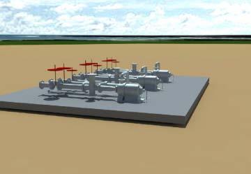
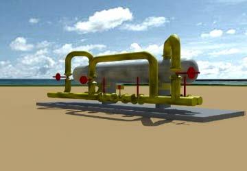
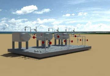
6 Natural Gas Purification and Treatment Equipment

7 Natural Gas Purification and Treatment Equipment Facilities for gas purification and treatment, oilfield associated gas collection, purification and treatment. More Efficient in Oil & Gas Extraction Page 7

8 Natural Gas Purification and Treatment Equipment Natural gas purification and treatment technology Skid-mounted natural gas processing equipment More Efficient in Oil & Gas Extraction Page 8
9 Natural Gas Purification and Treatment Process CO2 Recycle or Vent Sulfur H 2 S Sulfur Recovery Exhaust Gas Treatment To Purify Exhaust Gas (Flare Stack or Ven) Gas from Gas Well Oilfield Associated Gas sewage Three Phase Separator Three Phase Separator Gas Crude Oil Remove the Acidic Gas Condensate Crude Oil dehydration Dehydration Water Crude Oil Stabilization NGL Recycling C1 C 2 LPG(C 3 C 4 ) Natural Gas Oil (C 5 +) CNG LNG Sewage Deoiling sewage Commodity Crude Oil Oil Field Output Water (for Injection) More Efficient in Oil & Gas Extraction Page 9
10 Process Description Gas well gas will be separated into gas, sewage and condensate through separator. Oilfield associated gas will be separated into gas, sewage, crude oil. Then acid removal, water removal, NGL recovery process will be used for gas treatment to get the CNG, LNG, LPG and Natural gas oil. Commodity crude oil is obtained by dehydration and stabilization. The sewage water will be injected after de-oiling processing. More Efficient in Oil & Gas Extraction Page 10
 Hollow Fiber Membrane Silk in PI Process description Because of different permeability, gases with fast")

11 Purification Technology of Natural Gas Membrane Deacidification Technology Feed Gas Effluent Gas(permeable gas,h 2 S/CO2enriched) Dry Gas (nonpermeable gas, CH4 enriched) Hollow Fiber Membrane Silk in PI Process description Because of different permeability, gases with fast penetration rate including steam, H 2,Co 2, would firstly permeate the membrane and accumulate while gas with slow penetration rate including CO, CH 4, N 2 would be detained and accumulate, which successfully separates mixed gases. More Efficient in Oil & Gas Extraction Page 11
12 Natural Gas Purification Technology Amine sweetening processes Acid Gas Process Description Sweet gas Absorption Tower Outlet Separator Recycle Pump Defoamer Lean Amine Cooler Flash Distillation Tank Flash Distillation Gas Carbon Filter Buffer Tank Booster Pump Reflux Condenser Regeneration Tower Reflux Tank Add Water Remove the solid and liquid impurities from raw gas by inlet separator and then use alkanolamine absorber to remove acid gas. Separate the raw gas again to get relatively pure sweet gas. After flash distillation, heat exchange, regeneration, cooling and other Intlet Separator Drainage Liquid Hydrocarbon Anti-solid Filter Lean/Rich Amine Solvent Exchanger Reboiler processes, alkanolamine solution is recycled. Raw Gas Off-reactivating Boiler More Efficient in Oil & Gas Extraction Page 12
13 Natural Gas Purification Technology Natural Gas Pressure Boost Triglycol Dehydration Process Natural Gas Compressor-1 Air Cooler -1 Triglycol Dehydration Skid Export Process Description The gas will be separated, compressed, cooled and re- Separator-1 Separator -2 Drainage separated, and then feed into dehydration skid for water Compressor-2 Air Cooler -2 removal, then it will be exported. To Waste Oil Tank More Efficient in Oil & Gas Extraction Page 13
14 Natural Gas Purification & Treatment Technology Natural Gas Pressure Boost Molecular Sieve Dehydration Process Water of Dehydration Raw Gas Gas Lift Compressor Compressor Inlet Separator Compressor -2 Alkanol Injection Pump Methanol Air Cooler -1 Air Cooler -2 Compressor Outlet Separator 6 2 Molecular Sieve Dehydrator Drainage Drainage Process Description Remove the free water, oil and solids from the raw gas through the separator; compress the separated raw gas for twice to get high-pressure gas; and then remove the free water again through the compressor outlet separator. Inject methanol to prevent the gas from freezing before the raw gas enters the molecular sieve dehydration tower. Then dehydrate the high-pressure raw gas through high-pressure adsorption molecular sieve. More Efficient in Oil & Gas Extraction Page 14
15 Natural Gas Purification & Treatment Technology Natural Gas Pressure Boost Propane Low-temperature Dehydration and Heavy Hydrocarbon Removal Process Glycol Injection Pump Ethylene Glycol Process Description Remove the free water from the raw gas through the separator; compress Raw Gas Compressor -1 Compressor Inlet Separator Compressor-2 Air Cooler-1 Air Cooler -2 Ethylene Glycol Heat Exchanger export the separated raw gas for twice to get high-pressure gas; then remove the heavy hydrocarbon and water from the high-pressure gas through heat exchange, separation and cooling, and the dry gas will be exported. Before the gas enters the heat Drainage 3-phase Separator Propane Evaporimeter 3-phase Separator Heavy Hydrocarbon Fractional Distillation Unit exchanger, injection of ethylene glycol is required to prevent the gas from freezing. The ethylene glycol can be recycled and reused. Ethylene Glycol Rich Liquid Ethylene Glycol Regeneration More Efficient in Oil & Gas Extraction Page 15
16 Process of Throttling Cryogenic Cooling for Dehydration & Dehydrocarbon Ethylene Glycol Ethylene Glycol Heat Exchanger J-T Valve 3-Phase Separator Raw Gas Separator Ethylene Glycol Regeneration Fractional Distillation Drainage Dry Gas export Process Description Remove the free water from the raw gas through separator; cool down the separated raw gas through heat exchanger and decrease the temperature by adjusting the J-T valve; separate the dry gas, ethylene glycol rich solution and liquid hydrocarbon through the three-phase separator. Before the gas enters the heat exchanger and J-T valve, injection of ethylene glycol is required to prevent the gas from freezing. The ethylene glycol can be recycled and reused. More Efficient in Oil & Gas Extraction Page 16

17 Projects-natural gas purification and treatment Completed site survey, design and project execution of Hutubi gas field, Basin gas field, Mahe gas field, Kela Beatuty gas field, Kazakhstan Aryskum Natural gas treatment plant and more than 180 domestic and oversea projects. Completed natural gas production capacity of 16 billion m 3. More Efficient in Oil & Gas Extraction Page 17
18 Projects---natural gas purification and treatment Xinjiang karamay gas field natural gas treatment project Gas processing capacity: 3 x 10 6 m 3 /d LPG recovery and condensate oil treatment: 300 t/d More Efficient in Oil & Gas Extraction Page 18

19 Projects--natural gas purification and treatment The Xinjiang Basin fifth gas field surface construction project Natural gas processing: 1.5 x 10 6 m 3 / d. LPG recovery and condensate treatment : 300 t/d More Efficient in Oil & Gas Extraction Page 19

20 Projects--natural gas purification and treatment Xinjiang Oilfield Hutubi Gas storage project Natural gas processing: 4.5 x 10 9 m 3 / a. Gas injection : m 3 /a More Efficient in Oil & Gas Extraction Page 20

21 Projects--natural gas purification and treatment Xinjiang Mahe gas treatment plant Natural gas processing: m 3 /d; LPG recovery and condensate treatment : 300t/d More Efficient in Oil & Gas Extraction Page 21
 Pakistan KPD Section 667 project (a capacity of 7x10 6 Nm 3 /d ) More Efficient in Oil & Gas Extraction")
22 Projects--natural gas purification and treatment Ongoing projects Survey and design work for Aktyubinsk gas field construction project (designing capacity of 3x10 6 Nm 3 /d) Pakistan KPD Section 667 project (a capacity of 7x10 6 Nm 3 /d ) More Efficient in Oil & Gas Extraction Page 22
23 LPG Processing Plant

24 LPG Processing Plant Using a variety of refrigeration technology to collect C 3, C 4 component from raw gas, proceed SNG production according to the demand More Efficient in Oil & Gas Extraction Page 24

25 LPG Processing Plant LPG recycle and processing technology LPG recovery and condensate oil stability technology LPG mixed air SNG production technology More Efficient in Oil & Gas Extraction Page 25
26 LPG Recovery and Condensate Oil Stability Technology Expander refrigeration separation technology Second Stage Compression Air Cooler Feeding Gas First Stage Compression Air Cooler Interstage Separator Water Cooling Heat Interchanger Rich Gas Separator Sewage Three Stream Interchanger Dehydrating Water Molecular Sieve Dehydrator Sewage Second Stage Separator Sewage Air Cooler External Gas Light Oil Third Stage Compression Deethanizing Tower Expander Pressurized Side Expander Expanding Side Tower Top Condensator Liquefied Gas Tower liquefied gas Light Oil Condenser Light Oli More Efficient in Oil & Gas Extraction Page 26
27 Expander Refrigeration Separation Technology Process description The feed gas through two-phase separation, compression, air cooling (removal solid-liquid impurities, booster, cooling), through the heat exchanger in cooling water into the secondary separator, light hydrocarbon into steady light hydrocarbon isolated device; After the separation of gas into the molecular sieve unit after dehydration, the heat exchanger in cooling, into the deethanizer and lighter C1 and C2 components from the top of the tower into the expander refrigeration, provide cold energy for the heat exchanger, expansion of gas compression, transmission after cooling. Other components from ethane bottom out, into the gas tower, after a heavy light hydrocarbon liquid and flows into stable device, a lighter from liquefied gas on the top of C3 and C4 component, by condensation from liquefied gas products. More Efficient in Oil & Gas Extraction Page 27
28 LPG Recovery and Condensate Oil Stability Technology Propane refrigeration separation process Ethylene Glycol Gas Heat Exchanger Glycol Propane Evaporator Feed Gas Separator Three-phase Separator A Ethylene Glycol Rich Fluid Three-phase Separator B Light Hydrocarbon Sewage The Heater Dry gas H 2 O Dry gas Liquefied Gas Ethylene Glycol Regeneration Tower Ethylene Glycol Barren Fluid Buffer tank Deethanizer Mixed hydrocarbon Liquefied Petroleum gas Tower Cooler More Efficient in Oil & Gas Extraction Page 28
29 LPG Recovery and Condensate Oil Stability Technology Process description After raw material gas into liquid separator removes solid impurities, to prevent hydrate generated, adding glycol, after add alcohol gas after heat exchanger cooling into the three-phase separator, A lighter gases isolated again add alcohol after propane evaporators fell to A low temperature, B into the three-phase separator, again isolated gas as A fuel gas after heat exchange or transmission; Ethylene glycol isolated rich three-phase separator into the ethylene glycol regeneration unit, recovery of ethylene glycol; Three-phase separator liquid isolated after buffer into the deethanizer light hydrocarbon, lighter C1 and C2 components flowed from the top of the tower as a fuel gas or oil transmission, other components from ethane bottom out, into the gas tower, the heavier lighter hydrocarbon from liquefied gas tower bottom after cooling into the tank or transmission, and the lighter components of C3 and C4 from liquefied gas tower, by condensation from liquefied gas products. More Efficient in Oil & Gas Extraction Page 29
30 LPG Recovery and Condensate Oil Stability Technology J - T valve refrigeration separation technology Dry Gas Compressor Compressor Heat Exchanger J-Tvalve Cooler Liquefied Gas Feed Gas Separator Separator Heat Exchanger Separator Separator Deethanizer Debutanizer Sewage Flash Tank Separator Compressor Cooler Subcooler Heat Exchanger Light Oil Condensate Liquid Pump Cooler More Efficient in Oil & Gas Extraction Page 30
31 LPG Recovery and Condensate Oil Stability Technology Process description Feed gas by separator removed liquid solid impurities, with gas from the top of the deethanizer entering into the compressor to get pressurized, fell to a low temperature after heat exchanger, enter the separator, liquid hydrocarbon by flash tank is isolated from the flash, flash off gas back to the entrance of separator, liquid hydrocarbon after flash after cooling in the form of light oil transmission; Separator gas heat into the lower isolated separator, separator at the top of the flow of gas through the throttle valve throttle cooling further into the next level separator separation, the separation of gas as a fuel gas after heat pressure or transmission, after separation of the liquid hydrocarbon by pump pressurized into deethanizer and C1 and C2 lighter components flowed from the top of the tower into the level of the compressor, the other components by the heat transfer into the butane tower, heavy component from bottom in the form of light oil transmission, C3 and C4 flowed from the top of the tower after cooling the liquefied gas products. More Efficient in Oil & Gas Extraction Page 31

32 More Efficient in Oil&Gas Extraction Projects LPG factory Project: Xinjiang LPG Plant Project scale: LPG and condensate oil stability of 300 t/d More Efficient in Oil & Gas Extraction Page 32

33 More Efficient in Oil&Gas Extraction Projects LPG Plant Project:Xinjiang Oil filed CaiNan Gas Field LPG Plant Scale:LPG&Condensate oil, 300t/d More Efficient in Oil & Gas Extraction Page 33

34 More Efficient in Oil&Gas Extraction Projects LPG Plant Project:XinJiang ShiXi LPG Plant Scale:LPG & Condensate Oil Stable, 200t/d More Efficient in Oil & Gas Extraction Page 34
35 LPG Mixing Air Product SNG Technology Furnance Processing description Cool Water Hot Water Through pump increase energy, LPG was gasification by heat exchanger. The LPG Pump Heat Exchanger Mixer SNG gasification LPG mix with condense, dry air become SNG, SNG was used same function with pipeline gas equal burn heat value s commodity gas and city pipeline gas. Air Compressor Air Drier More Efficient in Oil & Gas Extraction Page 35
36 More Efficient in Oil&Gas Extraction Projects SNG Project:Zoomlion LPG Mixing Air Station Scale:Mixing capacity 8000Nm³/H More Efficient in Oil & Gas Extraction Page 36
37 CNG, LNG Processing Plant

38 CNG, LNG Processing Plant CNG, LNG Processing Technology CNG mother station, daughter station construction technology LNG processing plant technology LNG terminal technology 2x m 3 /d Natural gas plant renderings More Efficient in Oil & Gas Extraction Page 38
39 CNG Gas Station Introduction CNG Filling Gas Mother Station Process description The gas was feed from pipe network into CNG Gas Pipe Network Filter Metering Pressure Unit Dryer Compressor Buffer Tank Sequence Control Panel Mother station, through filtering, metering, drying, compressor boosting, stabilization tank, the gas will be distributed to different channel by sequence control panel. Daughter Station CNG Trailer Through filling gas column the natural gas is handling in CNG Trailer, transportation to daughter station. Through gas sales machine directly filling gas into Tanker Filling Gas Column automobile. Natural gas get into group gas storage cylinder to Gas Storage Cylinder storage. CNG Fuel Vehicle Gas Sale Machine More Efficient in Oil & Gas Extraction Page 39
40 CNG Gas Station Introduction CNG Gas Daughter Station Filter Process description CNG Trailer Unloading Arm Compressor Sequence Control Panel Filling natural gas in CNG Trailer through unloading arm to filter and compressor, removed impurity and boosting, and Gas Storage Cylinder then natural gas pass Sequence control panel to go to different channel. The gas will be injected to automobile CNG Fuel Automobile Gas Sale Machine through gas sale machine. To be stored in storage cylinder More Efficient in Oil & Gas Extraction Page 40
41 LNG Project Introduction It includes LNG liquefaction plant, LNG terminal station, LNG Gas Station, LNG Refueling Station (Mother station, Daughter station). The LNG Refueling Station process is similar with CNG gas station.
42 Natural Gas Liquefaction Plant Condenser Dust Filter ACF Demercuration Compressor Gas Liquid Separator Cold Box LNG Storage Tank Condenser Feed Gas Gas Liquid Separator Sewage Compressor Condenser Gas liquid separa tor Absorption Tower Gas Liquid Separator Molecular Sieve Dehydration Unloading BOG Acid Gas Sewage Sewage Flash Drum Amine Liquid Regeneratio n Condenser More Efficient in Oil & Gas Extraction Page 42
43 Natural Gas Liquefaction Plant Process description Remove liquid and soild impurities from the raw gas through gas liquid separator, increase the pressure of the raw gas by compressor and cool down by condenser; remove the sulfur and car bon in the absorption tower.after removing the acid, cool and separate the gas through condenser and separartor, and dehydrate the gas through molecular sieve; after dehydeating, using filter to remove the mecury through removal unit; futher decrease the temperature of the gas through heat exchanger; finally store the liquefied natural gas int the storage tank. The amine rich solution which flows from the bottom of the absorption tower is recycled and reused. More Efficient in Oil & Gas Extraction Page 43
44 LNG Receiving Terminal Process description LNG Vessel Recovered Gas Compressor Long-distance Gas Transit line Metering Station As a facility to storage and transport LNG, LNG Receiving terminal has the following technical process: LNG is shipped to the dock by LNG vessel and unloaded into the LNG storage tank for storage at the LNG Receiving terminal. The LNG is gasified according to Re-Condenser Open-frame Sea Water Gasifier client s requiremenets. The vapor from LNG ships and LNG storage tank is then re-compressed and re-condensed into liquefied natural gas through recovered gas compressor and re- Submerged Combustion Gasifier condenser. Afterwards, this liquefied natural gas, together with the LNG from the storage tank, is gasified through gasifies and feed into the metering station to decrease the LNG Storage Tank LNG Tanker pressure. Finally the gas is exported via pipeline. Another part of the LNG from the LNG storage tank is loaded to tankers for transportation to the gas filling stations. More Efficient in Oil & Gas Extraction Page 44
45 LNG Gasification Station Process description BOG Heater LNG gasification station is a receiving, LNG Tanker BOG Gas Storage Tank storage and distribution satellite station, as well as a intermediate station where towns or gas companies transfer gas from the manufacturers to the end-users. LNG Storage Tank Outlet Main Pipe The main process is as follows: Unload LNG from tankers to storage tank. Flash steam flows from the tank top and is heated by BOG heater before entering the BOG storage tank. Then the LNG flow out Pressure Boost Gasifier Air-temperature Primary Gasifier Water Bath Heater stench-adding machine from the bottom of the tank, and is gasified and heated. Finally, the LNG, together with the flash vapor, is added with stench and flows out. More Efficient in Oil & Gas Extraction Page 45

46 More Efficient in Oil&Gas Extraction Projects LNG CNG Project: Nanning LNG Gas Station Gasification capacity: 1.2X10 4 Nm³/H More Efficient in Oil & Gas Extraction Page 46


47 Projects LNG CNG Hami LNG Plant Yunnan LNG Station Miton CNG Refueling Mother Station Shanxi Sanjiao CNG filling station extension project More Efficient in Oil & Gas Extraction Page 47
48 Natural Gas Station & Utilities


49 Natural Gas Station & Utilities Gas Diesel power station Hot oil heater system Instrument air system Fueling system Nitrogen system Water treatment system Flare stack system More Efficient in Oil & Gas Extraction Page 49
50 Natural Gas Power Generation Device Gas Generator Set Gas Natural Gas Pretreatment User Transformer Recycling Cooling Water System More Efficient in Oil & Gas Extraction Page 50
51 Diesel Generator Set Diesel Generator Set Diesel User Transformer Recycling Cooling Water System More Efficient in Oil & Gas Extraction Page 51
52 Hot Oil Heater System Hot Oil Heating Equipment No.1 Heating Equipment No.2 Hot Oil Heater Fuel Gas Fuel Gas Buffer Tank Circulation Pump (alternate) Circulation Pump The oil was heated into designed temperature and the hot oil was pumped into heating equipment for heat exchange. The cooled oil was pumped into the heater via circulation pump for heating again, which forming a complete heating systems. More Efficient in Oil & Gas Extraction Page 52
53 Instrument Air System Air Utility Gas Storage Tank Air Filter Air Compressor Set Pre-filter Dryer A Dryer B Pneumatic Instrument No.1 Pneumatic Instrument No.2 Instrument Air Tank Post-filter Pneumatic Instrument No.3 After the air passes through air filter to filter out dust and dirt, it is compressed by the compressor, into the utility gas storage tank. Compressed air will be stored in buffer tank for some time, the moisture carried in the air and particles are further separated, the separated air, is dried, enters the tank meter, supply air for the pneumatic instrument. There are two sets of dryers for each system, one for dryer, another one for regenerating. The air must be feed from the bottom of the dryer and export from the top. More Efficient in Oil & Gas Extraction Page 53
54 Fuel Systems Filter No.1 Fuel Tank Fuel User Pump No.1 Filter No.2 Pump No.2 The fuel was pumped from the bottom of the tank, it will be filtered for solid impurities removed in the filter, then transported to fuel user. More Efficient in Oil & Gas Extraction Page 54
55 Nitrogen System Hot Oil Expansion Tank Nitrogen Storage Tank Hot Oil Storage Tank Nitrogen Generation Equipment Instrument Air System Amine Storage Tank The nitrogen generated from the Nitrogen generation equipment will be stored in the tank. Then it will be distributed to hot oil expansion tank, hot oil storage tank, instrument air system and amine storage tank for nitrogen seal. More Efficient in Oil & Gas Extraction Page 55
56 Water Treatment Circulation Pump Heat Exchanger corrosion Inhibitor Injection Scale Inhibitor Injection Bactericidal Algaecide Injection Cooling Tower Feed Water Water Pool The used water will be flows to the water pool via cooling down by the cooling tower. Chemicals will be injected into the water pool(corrosion inhibitor, scale inhibitor and bactericidal algaecide ), then the water can be used for heat exchangers. Water should be feed once water was lost because of evaporation. More Efficient in Oil & Gas Extraction Page 56
57 Ground Flare System Radiation Heat Shield Long Term Burny Flames Ignition Control Box AC220V 50HZ Igniter High Pressure Generator Anti- backfire Device Flare Ignition Fuel Gas Vent Gas Water Sealing Tank Knock-out Drum Acid Gas Tank Acid Gas More Efficient in Oil & Gas Extraction Page 57
58 Flare Stack System Long Term Burny Flames Igniter Ignition Control Box AC220V 50HZ Flare High Pressure Generator Anti-backfire Device Ignition Fuel Gas Vent Gas Water Sealing Gas Knock Out Drum Acid Gas Tank Acid Gas More Efficient in Oil & Gas Extraction Page 58
59 Two source for flare gas: One is overall plant all unit emission air, emission though separate tank dehydration, get into water sealed tank, go against water sealed get into torch burning. Another source is the production process emission toxic acidity gas, through acid gas tank get into torch burning. The ignition control boxes control fuel gas transmission to igniter, as soon as activate high voltage cable transmission to high voltage ignition electrode arc ignition. More Efficient in Oil & Gas Extraction Page 59
60 Natural Gas Injection Station
61 Natural Gas Injection Station Compressor Cooler Molecular Sieve Dehydration Process description Feed gas firstly goes to separator to Feed Gas Separator High efficient separator get free water and liquid hydrocarbons,then goes to compressor before cooler. Pressurized feed gas goes to high efficient To effluent oil treatment system Slop Tank separator to get free water and liquid hydrocarbons again. Separated natural gas goes to molecular sieve To Gasinjection Well Cooler Compressor Metering Skid dehydration to get rid of water, then will be sent to injection well after metering, pressurizing and cooling. More Efficient in Oil & Gas Extraction Page 61
62 Skid Mounted Natural Gas Plant


63 Skid Mounted Natural Gas Plant Input separation unit Ethylene glycol recycle and regeneration unit Propane cooling unit More Efficient in Oil & Gas Extraction Page 63


64 Skid Mounted Natural Gas Plant Liquefied gas tower LPG-natural gas heat exchange unit Liquid Gas Storage Tank More Efficient in Oil & Gas Extraction Page 64


65 Skid Mounted Natural Gas Plant Stabilization light hydrocarbon Tank Heat Exchanger Loading/Unloading More Efficient in Oil & Gas Extraction Page 65

66 Skid Mounted Natural Gas Plant LPG unloading/unloading Heat Exchanger Ethylene Glycol Injection Skid More Efficient in Oil & Gas Extraction Page 66


67 Skid Mounted Natural Gas Plant Nitrogen Station The Hot Medium Heater Recycle pump Skid More Efficient in Oil & Gas Extraction Page 67


68 Deethanizing Column Unit Condensate buffer tank Deethanizing column bottom Reboiler More Efficient in Oil & Gas Extraction Page 68


69 Skid-mounted Products Integrated heating three-phase separator Quadruple effect separator Light hydrocarbon recovery Methanol injection Launching/receival chamber Metering system More Efficient in Oil & Gas Extraction Page 69


70 Skid-mounted Products Metering separator Wellhead gas separator Molecular sieve dehydration TEG dehydration Membrane deacidification Amine deacidification More Efficient in Oil & Gas Extraction Page 70
71 Experiences List No. Project Location Scale of Construction Start Date Completion Date SOP Time 1 Xinjiang Shixi Natural Gas processing project China m3/d Xinjiang Basin-5 gas field surface construction project China m3/d Xinjiang Mobei gas field surface construction project China m3/d Xinjiang oil extraction second plant Natural Gas Processing Plant China m3/d Xinjiang Mahe gas field surface construction project China m3/d Xinjiang Oilfield Kelameili gas field 2nd phase surface construction project China m3/d Xinjiang oilfield company Hutubi gas storage project China m3/d Xinjiang Ake gasfield surface construction project China m3/d More Efficient in Oil & Gas Extraction Page 71
72 Oversea Experiences List No. Project Name Country Scale of Construction Start Date Completion Date SOP Time 1 Zanarol oil field the third stage oil&gas treatment plant PhaseⅠGas supply project Kazakhstan design scale Nm3/d Zanarol oil field gas lift system reconstruction project Kazakhstan design scale Nm3/d Hope oil field productivity construction (first-stage project )oil transfer station and supporting facilities Kazakhstan m3/d Zanarol oil field Moisture reinjection project Kazakhstan Gas injection station scale Nm 3 /a Gas distribution station scale Nm 3 /a Pakistan KPD block 667 natural gas treatment plant Pakistan m3/d Kazakhstan Sary-Bulak gas field surface constrction project Kazakhstan m3/d AYSKUM oil field natural gas treatment station project Kazakhstan m3/d More Efficient in Oil & Gas Extraction Page 72

73 An International Enterprise with Great Global Marketing and Service Network 45 Global Branch Organization More Efficient in Oil & Gas Extraction Page 73


74 More Efficient in Oil & Gas Extraction More Efficient in Oil & Gas Extraction Page 74