Ten glorious years of service to industry & customers ENGINEERING SERVICE OVER VIEW & IMPORTANT PROJECT- CASE STUDY
|
|
|
- John Booth
- 5 years ago
- Views:
Transcription
1 ENGINEERING SERVICE OVER VIEW & IMPORTANT PROJECT- CASE STUDY

2 STRESS ANALYSIS Structural Strength of Turbine Casing Client : Hydro Power sector Scope of work: To analyse the given structure to bear the operating loads [Shaft and generator assembly seated at top of housing Kgf] Input: Component drawing & GA drawings Material Properties and other data Delivery: Analysed stress developed and the displacement. Compared with GES. Recommended additional stiffeners, revised stress and displacement and engineering drawings Covenant Standards: IS 800:2007 & GES


3 CFD HYDRAULIC FLOW Flow & strength analysis of pelton turbine Client : Hydro Power equipment manufactures Scope of work: To find out flow characteristic of nozzle and turbine efficiency Input: Component & GA drawings Flow data Application data Output: Predicted velocity, pressure & turbulence characteristics of flow, also arrived force & Torque excreted on the bucket due to flow impingement. Hydraulic efficiency is arrived trough CFD results and compared with classical approach results. Covenant Standards: Publication & Journals

4 FATIGUE ANALYSIS Fatigue analysis of Pelton turbine bucket Client : Hydro Power equipment manufactures Scope of work: Life estimation of the Pelton turbine bucket due to cyclic water jet impingement Input: Component drawings, Material data Application data Delivery: SN curve for the steel material, Good man diagram technique used Analyzed stress is 200MPa, according to the SN curve 2 x 10 6 cycles for 300 MPa, confirmed the part is safe for intended life Covenant Standards: Publications and ASTM


5 CFD HYDRAULIC FLOW Flow analysis and efficiency calculation for Pit turbine Client : Hydro Power equipment manufactures Scope of work: To find the flow characteristics for the hydraulic pit passage. Blade torque and vane torque calculation is the aim of this study Input: 3D assembly model Flow specifications Application data Output: : Arrived flow characteristic like velocity, pressure and viscosity across the pit passage. Force/torque excreted on the guide vanes and rotor blades are observed. The hydraulic efficiency is arrived through CFD results and the same is confirmed by classical approach.


6 3D MODEL VIEW & BC- EXISTING Proof Load 450Kgs Fixed all DOF at bottom


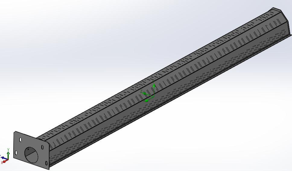
7 PROPOSED MODEL Support added as rectangular tube of 96x48x4 mm

8 STRESS PLOT Average Stress < 150 MPa

9 DISPLACEMENT PLOT Displacement Max. 14 mm Displacement reduced from 34mm to 14mm and stress average is from 250 to 150Mpa for the proof load of 450Kgs. Its observed that support is giving enough holding strength for operating load of 250Kgs.


10 HONEY COMB MODEL Honey comb web thickness 3mm Hexagonal Diameter 75 mm
11 RESULT SUMMARY Honey comb Model Solid Model Sl.No Load Stress in MPa Displacement in mm Stress in MPa Displace ment in mm 1 Fully Compressive Along the flow (Tangential) Normal to bottom/high pressure face Weight 90 Kg 310Kg 5 TOTAL WEIGHT SAVING FOR FULL TURBINE-5.1 T
12 SOLUTIONS OFFERED FLUID FLOW ANALYSIS

 for the unit and recommended bolt sizes to Bolt sizes/ fasteners to withstand wind forces.")
13 CFD- AIR FLOW Drag force estimation on roof mounted a/c unit Client : Rolling stock manufacturer and wanted to estimate the bought out a/c unit when mounted on roof top can withstand wind drag force at 130 kmph speed. Input: 3D assembly model and holding down arrangement Output: : Arrived at force exerted on the front and rear face of unit, Worked out Coefficient of drag (C d ) for the unit and recommended bolt sizes to Bolt sizes/ fasteners to withstand wind forces. Covenant Standards: Publications and Journals, NES & GES


14 HYDRAULIC ANALYSIS Project Objective: Development of mixed flow pump Reduction in development time & Cost Approach Based on Flow simulation assessment of delivery parameters & optimisation. Rapid Prototyping Generation of Master Pattern of impeller & diffuser bowls Achievements Reduced no. of trials Shortened development time. Improved design with better tolerance & achievement of predicted values.


 and 9.")
15 HYDRAULIC ANALYSIS Results: New model designed with improved characteristics [Flow Vs Head] Impeller vanes angles optimised to improve efficiency without compromise on delivery parameters. Two stage pump proposed and overall efficiency improved with savings in power. Maximum head obtained is 9.2 m (actual) and 9.32 m (flow simulation ) Trials & tests conducted for two stage assembly validated the model.
 5 (input) 2 Average Velocity, U (m/s) 2.311 2.484 2.")
16 RESULT COMPARISON Sl.No Parameters IISC report Pipe As per CFD As per calculation 1 Flow rate Q (lps) (ṁ) 5 (input) 2 Average Velocity, U (m/s) Pressure difference (Pa) Reynolds number 128, ,663


17 DEFECT ANALYSIS Bearing Life Improvement: One of the hydraulic turbines was facing premature bearing failure. CFD analysis was taken up and study revealed uneven flow resulted in side thrust which was not envisaged. Correction by way of providing additional guide vanes has resulted in non stop operation since last 2 years DUCT ASSEMBLY1.0 DUCT ASSEMBLY2.2 [Final Iteration]
18 SOLUTIONS OFFERED THERMAL ANALYSIS
19 CFD- TRANSIENT THERMAL ANALYSIS Thermal Analysis of Module using CFD Client : Electronic hardware manufacture. Requirement: To find the thermal distribution and to access efficiency of heat sink for the ambient temp. of 25 & 80 0 C and estimate internal temperatures Input: Enclosure and component drawings Thermal characteristics of components and transient heating properties based on firing cycle. Delivery: Temperature distribution at each section w.r.t time. Found heat sink is adequate to maintain internal temp at 89 0 C with ambient at 80 0 C
20 CFD-THERMAL Methodology: Transient analysis ambient temp. of 25 0 C and 80 0 C Output: Temperature distribution at each section plotted and values tabulated. Heat sink provided validated for sufficiency. Temp 5-7 deg increase


21 CFD - THERMAL ANALYSIS Thermal & Structural analysis of electronic cabinet- Covenant stds: NES Client : Manufacturer of power amplifier/supply unit for ship borne application Requirement: 1. Assess forced cooling air fan requirement to maintain internal temperature of cabinet at less than 5 deg C 2. Validate cabinet structural stability to withstand ship motion under cyclonic storm, stability under steady low frequency vibration. Input: 3D assembly model, air input and ambient conditions, limiting conditions Output: : Optimised fan location and sizing. This included relocation rearrangement of internals. In order to keep the fan power at low values, recommended bleeding so that fresh cool air mixes at each level with arm air.


22 THERMAL ANALYSIS-CABINET Ten glorious years of service to industry & customers Project Description: Design of cooling passages and fan requirement to keep internal temp between 20 to 40 deg C ; Shock strength to meet 50 g as per NSS standards Customer: Defence


23 AIR FLOW PLOTS Flow lines at higher elevation Temperature Plot Flow lines at higher elevation Velocity Plot Heating oven air flow analysis

24 HEATING OVEN ANALYSIS Pressure Plot
25 WATER FILTER To Carry out CFD analysis to determine simulated flow conditions and to assess distribution pattern of water inside the filter housing.
26 MODEL

27 LID POSITION LID 2 LID 3 LID 4 LID 5 LID 6 LID 1 LID 1 is located 12 from the entry face & LID 7 is located 12 from the rear face. Rest of LIDs located 14 equi-spaced. [LID-Local Inference Desired]

28 ANNULAR SPACE FLOW In between the cambers
29 SUMMARY OF RESULTS SUBMERGED CONDITION 12IN OF WC Location Av Static Pressure Difference in Pressure Av Total Pressure Av Dynamic Pressure Volume Flow Rate Volume Flow Rate Customer Given Av Velocity [Pa] [Pa] [Pa] [Pa] [l/min] GPM GPM [m/s] LID 1 -Inner LiD 1 -Between LID 2 -Inner LiD 2 -Between LID 3 -Inner LiD 3 -Between LID 4 -Inner LiD 4 -Between LID 5 -Inner LiD 5 -Between LID 6 -Inner LiD 6 -Between
30 SHOCK & VIBRATION ANALYSIS


31 SHOCK ANALYSIS Shock Load 50 g and maximum shock above SV mounts 27 g Covenant Standards: NES & BR3021
32 SHOCK ANALYSIS Input Load curve Post Attenuation Loading (27g)

33 DROP TEST Drop test for battery cover: BR 3021 & IS13035 Client : Communication & health care equipment manufactures Scope of work: To find the structural integrity of Battery pack assembly under impact due to fall / drop from 0.75m of height. Input: 3D solid model and Material data Output: : Independently analysed stress due to impact load on all six faces plus corner.identified corner impact has highest stress generated. Small change in Battery holding arrangement within pack improved shock ability Plot step - 1 Plot step - 2 Plot step - 5 Plot step - 10 Plot step - 15 Plot step - 25

34 PLASTIC ANALYSIS To understand the mold flow parameters and warpage details of component 3D MODEL VIEW Front Face Rear Face

35 MATERIAL & INJECTION POINTS Material Used : Plastics Injection points as per below image: Diameter of injection hole 4mm
36 FILL TIME 1.14 sec required to fill the mold material
37 AIR TRAP PLOT Red mark points are indicated air traps

38 WARPAGE PLOT Total deformation of 1.6mm observed Deformation scale set as 3
39 SUMMARY OF SERVICE OFFERED Tank and tank internal design as per API code FEM based Structural analysis Thermal analysis using CFD techniques Hydraulic flow analysis using CFD techniques Pressure Vessel Design as per ASME code Shock & Vibration analysis Interactive Electronic Technical Manual Training. Marine services-basic and detailed design and naval Architectural interventions.


40 CLIENTELE Eureka Forbes
41 Thank You